Manuale per il collegamento e l uso Installation and operation manual Manuel pour le raccordement et l emploi
|
|
|
- Marguerite Aubé
- il y a 8 ans
- Total affichages :
Transcription
1 Manuale per il collegamento e l uso Installation and operation manual Manuel pour le raccordement et l emploi EBM2 KLYS 9CD attuatore per basculante SLAVE 24 V 9 m 2 KLYS 9CD actuator for up-and-over garage door SLAVE 24 V 9 m 2 KLYS 9CD actuateur pour portes basculantes SLAVE 24 V 9 m 2 KLYS 9CD

2 IMPORTANTI ISTRUZIONI PER LA SICUREZZA ATTENZIONE - PER LA SICUREZZA DELLE PERSONE È IMPORTANTE CHE VENGANO SEGUITE TUTTE LE ISTRUZIONI CONSERVARE CON CURA QUESTE ISTRUZIONI 1 - Se non è previsto nel quadro elettrico, installare a monte del medesimo un interruttore di tipo magnetotermico (onnipolare con apertura minima dei contatti pari a 3 mm) che riporti un marchio di conformità alle normative internazionali. Tale dispositivo deve essere protetto contro la richiusura accidentale (ad esempio installandolo entro quadro chiuso a chiave). 2 - Per la sezione ed il tipo dei cavi la ELVOX consiglia di utilizzare un cavo di tipo H05RN-F con sezione minima di 1,5 mm 2 e comunque di attenersi alla norma IEC 3120 e alle norme di installazione vigenti nel proprio Paese. 3 - Posizionamento di un eventuale coppia di fotocellule: il raggio delle fotocellule deve essere ad un altezza non superiore a 70 cm dal suolo e ad una distanza dal piano di movimento della porta non superiore a 20 cm. Il loro corretto funzionamento deve essere verificato a fine installazione in accordo al punto della EN Per il soddisfacimento dei limiti imposti dalla EN 12453, se la forza di picco supera il limite normativo di 400 N è necessario ricorrere alla rilevazione di presenza attiva sull intera altezza della porta (fino a 2,5 m max). Le fotocellule in questo caso sono da applicare all esterno ed all interno ad una distanza dal piano di movimento della porta non superiore a 20 cm, ogni cm per tutta l altezza della porta fino ad un massimo di 2,5 m (EN punto ) N.B.: È obbligatoria la messa a terra dell impianto I dati descritti nel presente manuale sono puramente indicativi. La ELVOX si riserva di modificarli in qualsiasi momento. Realizzare l impianto in ottemperanza alle norme ed alle leggi vigenti. ISTRUZIONI IMPORTANTI DI SICUREZZA PER L INSTALLAZIONE ATTENZIONE - L INSTALLAZIONE NON CORRETTA PUÒ CAUSARE GRAVI DANNI SEGUIRE TUTTE LE ISTRUZIONI DI INSTALLAZIONE 1 - Questo libretto d istruzioni è rivolto esclusivamente a del personale specializzato che sia a conoscenza dei criteri costruttivi e dei dispositivi di protezione contro gli infortuni per i cancelli, le porte e i portoni motorizzati (attenersi alle norme e alle leggi vigenti). 2 - L installatore dovrà rilasciare all utente finale un libretto di istruzioni in accordo alla L installatore dovrà applicare in prossimità dei comandi o della basculante delle etichette di attenzione sui pericoli da intrappolamento. 4 - Controllare spesso l impianto, in particolare i cavi, le molle e i supporti per scoprire eventuali sbilanciamenti e segni di usura o danni. L utente finale non deve azionare elettricamente la basculante se questa necessita di manutenzione o riparazione dal momento che un guasto all installazione o una porta non correttamente bilanciata può provocare ferite. 5 - L installatore prima di procedere con l installazione deve prevedere l analisi dei rischi della chiusura automatizzata finale e la messa in sicurezza dei punti pericolosi identificati (seguendo le norme EN / EN 12445). 6 - L installatore prima di installare il motore di movimentazione deve verificare che la basculante sia in buone condizioni meccaniche e che si apra e chiuda adeguatamente. 7 - L installatore dovrà installare l organo per l attuazione del rilascio manuale ad un altezza inferiore a 1,8 m. 8 - L installatore dovrà rimuovere eventuali impedimenti al movimento motorizzato della basculante (es. chiavistelli, catenacci, serrature ecc.) 9 - L installatore dovrà applicare in modo permanente le etichette che mettono in guardia contro lo schiacciamento in un punto molto visibile o in prossimità di eventuali comandi fissi Il cablaggio dei vari componenti elettrici esterni all operatore (ad esempio fotocellule, lampeggianti, ecc.) deve essere effettuato secondo la EN e le modifiche a questa apportate dal punto della EN Tenete i comandi dell automatismo (pulsantiera, telecomando etc.) fuori dalla portata dei bambini. I comandi devono essere posti ad un altezza minima di 1,5 m dal suolo e fuori dal raggio d azione delle parti mobili Prima di eseguire qualsiasi operazione di installazione, regolazione, manutenzione dell impianto, togliere la tensione agendo sull apposito interruttore magnetotermico collegato a monte dello stesso A fine installazione l installatore dovrà assicurarsi che le parti della porta non ingombrino strade o marciapiedi pubblici A fine installazione l installatore dovrà assicurarsi che il motore di movimentazione prevenga o blocchi il movimento di apertura quando la porta è caricata con una massa di 20 kg, fissata al centro del bordo inferiore della porta. LA DITTA ELVOX NON ACCETTA NESSUNA RESPONSABILITÀ per eventuali danni provocati dalla mancata osservanza nell installazione delle norme di sicurezza e delle leggi attualmente in vigore. Direttiva 2002/96/CE (WEEE, RAEE). Il simbolo del cestino barrato riportato sull apparecchio indica che il prodotto, alla fine della propria vita utile, dovendo essere trattato separatamente dai rifiuti domestici, deve essere conferito in un centro di raccolta differenziata per apparecchiature elettriche ed elettroniche oppure riconsegnato al rivenditore al momento dell acquisto di una nuova apparecchiatura equivalente. L utente è responsabile del conferimento dell apparecchio a fine vita alle appropriate strutture di raccolta. L adeguata raccolta differenziata per l avvio successivo dell apparecchio dismesso al riciclaggio, al trattamento e allo smaltimento ambientalmente compatibile contribuisce ad evitare possibili effetti negativi sull ambiente e sulla salute e favorisce il riciclo dei materiali di cui è composto il prodotto. Per informazioni più dettagliate inerenti i sistemi di raccolta disponibili, rivolgersi al servizio locale di smaltimento rifiuti, o al negozio in cui è stato effettuato l acquisto. Rischi legati alle sostanze considerate pericolose (WEEE). Secondo la nuova Direttiva WEEE sostanze che da tempo sono utilizzate comunemente su apparecchi elettrici ed elettronici sono considerate sostanze pericolose per le persone e l ambiente. L adeguata raccolta differenziata per l avvio successivo dell apparecchio dismesso al riciclaggio, al trattamento e allo smaltimento ambientalmente compatibile contribuisce ad evitare possibili effetti negativi sull ambiente e sulla salute e favorisce il riciclo dei materiali di cui è composto il prodotto. 2 I

3 CARATTERISTICHE TECNICHE / INSTALLAZIONE KLYS 9CD SLAVE Porte basculanti max 12 m 2 EBM1 EBM2 EBX7 EBX1 EBX4 EBX2 EBX6 n 1 - EBM1 - KLYS 9CD MASTER dx con finecorsa senza longherone n 1 - EBM2 - KLYS 9CD SLAVE dx senza longherone n 1 - EBX7 - Longherone L = 1,95 m per basculante non predisposta alla motorizzazione n 1 - EBX1 - Longherone L = 0,8 m per basculante predisposta alla motorizzazione n 1 - EBX4 - Rinvio laterale per 2 motori L = 30 cm n 1 - EBX2 - Coppia leve diritte (oppure EBX6 - Coppia leve curve) CARATTERISTICHE TECNICHE 1950 (longherone lungo) 800 (longherone corto) 703 KLYS 9CD è un operatore irreversibile utilizzato per movimentare porte basculanti bilanciate a contrappesi. È completo di un gruppo riduttore lubrificato con grasso sintetico, di uno sblocco manuale in mancanza di corrente e di un longherone (opzionale) per il fissaggio dell operatore alla basculante. La protezione IP44 di serie permette a KLYS 9CD di essere protetto da spruzzi d acqua provenienti da tutte le direzioni. KLYS 9CD SLAVE, abbinato a KLYS 9CD MASTER, e dotato di illuminatore a led, regolazione della velocità e sensore d impatto in conformità alle Norme europee in vigore. CARATTERISTICHE TECNICHE Lunghezza max leva basculante Superficie max basculante Larghezza max basculante Altezza max basculante Coppia max 1 motore Giri al minuto dell operatore KLYS 9CD MASTER cm 83 m 2 12 (2 motori) m 6 (2 motori) m 2,5 Nm 350 rpm 1, ,5 147 Tempo di apertura regolabile Alimentazione di linea Alimentazione motore s V ~ 50 Hz 24 Vdc Potenza 1 motore W 55 Assorbimento linea di rete A 1,2 Cicli giornalieri consigliati max n 36 Servizio 80 % Peso kg 9,5 MASTER - 8 SLAVE Misure in mm 1 Rumorosità Temperatura di lavoro db <70 C C Grado di protezione IP 44 I 1

4 La leva della basculante deve avere una lunghezza massima di 83 cm Operatore KLYS 9CD MASTER + 1 operatore KLYS 9CD SLAVE 2 - Antenna radio 3 - Lampeggiatore 4 - Selettore a chiave 5 - Bordo sensibile 6 - Fotocellule interne CONTROLLO PRE-INSTALLAZIONE Per porte con larghezza fino a 6 m, altezza massima 2,5 m o comunque fino a 12 m 2 di superficie e leva della basculante con lunghezza massima 83 cm, si utilizzano 2 KLYS 9CD (MASTER EBM1 + SLAVE EBM2) montati come mostra la Fig. 3, una COPPIA DI LEVE DIRITTE cod. EBX2 (o una COPPIA DI LEVE CURVE cod. EBX6), il RINVIO LATERALE per 2 motori cod. EBX4 e 2 cod. EBX1 LONGHERONI CORTI o 2 cod. EBX7 LONGHERONI LUNGHI. - Verificare che lo spazio compreso tra il telaio mobile della porta e i cassonetti che contengono i contrappesi sia superiore a 15 mm. In questo caso è possibile montare le LEVE DIRITTE. Se tale distanza risulta essere inferiore a 15 mm, utilizzare le LEVE CURVE rispettando le quote di montaggio descritte in Fig Verificare che i cuscinetti di scorrimento della porta basculante non siano bloccati e che le funi di fissaggio dei contrappesi siano in buono stato. - Togliere, se esistente, la leva di chiusura manuale collegata alla serratura. N.B. È obbligatorio uniformare le caratteristiche della basculante alle norme e leggi vigenti. La basculante può essere automatizzata solo se in buono stato e se rispondente alla norma EN Non bisogna generare punti di intrappolamento (ad esempio tra basculante aperta e parete). COMPONENTI DA INSTALLARE SECONDO LA NORMA EN12453 TIPO DI COMANDO USO DELLA CHIUSURA Persone esperte Persone esperte Uso illimitato (fuori da area pubblica*) (area pubblica) a uomo presente A B - a impulsi in vista (es. sensore) C o E C o E C e D, o E a impulsi non in vista (es. telecomando) C o E C e D, o E C e D, o E automatico C e D, o E C e D, o E C e D, o E 3 * esempio tipico sono le chiusure che non accedono a pubblica via A: Pulsante di comando a uomo presente (cioè ad azione mantenuta), B: Selettore a chiave a uomo presente, come cod. EDS1 C: Regolazione della forza del motore D: Bordi sensibili e/o altri dispositivi di limitazione delle forze entro i limiti della norma EN Appendice A. E: Fotocellule, es. cod. EFA1 (Da applicare ogni cm per tutta l altezza della porta fino ad un massimo di 2,5 m - EN punto ) 2 I
, il RINVIO LATERALE per 2 motori cod. EBX4 e 2 cod. EBX1 LONGHERONI CORTI o 2 cod. EBX7 LONGHERONI LUNGHI.")
5 MONTAGGIO DI 2 KLYS 9CD PER PORTE FINO A 12 m 2 APPLICAZIONE LEVE 35 mm 55 mm ANGOLARI FODERO DELLE LEVE ANGOLARI FODERO DELLE LEVE 4 40 mm 5A 5B MONTAGGIO DELLA COPPIA LEVE DIRITTE (cod. EBX2) TRA MOTORE E TELAIO SUPERIORE DELLA PORTA N.B.: La COPPIA LEVE DIRITTE TELESCOPICHE si può montare quando tra la parte mobile della porta e il cassonetto che contiene il contrappeso esiste uno spazio minimo di 15 mm. - Con rivetti o viti si dovranno fissare gli angolari al telaio superiore rispettando le misure presenti in Fig. 4: se alla quota 35 mm, si trova la piastra di rinforzo del telaio della basculante, e possibile fissare le staffe direttamente sopra alla piastra anche se la quota non potra essere rispettata. Nel caso la basculante sia già predisposta per la motorizzazione utilizzare gli appositi agganci. Non utilizzare gli angolari forniti. - Inserire i foderi delle leve negli angolari e fissare con gli appositi perni e copiglie (Fig. 4). - Prestare attenzione affinchè una volta montati i foderi non urtino contro le leve di movimento della basculante. MONTAGGIO DELLA COPPIA LEVE CURVE (cod. EBX6) TRA MOTORE E TELAIO SUPERIORE DELLA PORTA N.B.: La COPPIA LEVE CURVE TELESCOPICHE è necessaria quando lo spazio compreso tra il telaio mobile della porta e i cassonetti che contengono i contrappesi è meno di 15 mm. - Nel caso la basculante sia già predisposta per la motorizzazione utilizzare gli appositi agganci. Non utilizzare gli angolari forniti. - Inserire i foderi delle leve negli angolari e fissare con gli appositi perni e copiglie (Fig. 4). - Prestare attenzione affinchè una volta montati i foderi non urtino contro le leve di movimento della basculante. N.B.: La lunghezza del fodero e delle leve va modificata a seconda dell altezza della basculante. E necessario quindi accorciare sia il fodero che la leva in maniera che a porta aperta il fodero disti 40 mm dal centro del perno di traino e la leva non urti contro il perno di rotazione posizionato sugli angolari (Fig. 5A) APPLICAZIONE LONGHERONE LUNGO (PER BASCULANTI NON PREDISPOSTE ALLA MOTORIZZAZIONE) Cod. EBX7 Posizionare il longherone tenendo la parte superiore (asola passaggio cavi elettrici) rivolta verso l alto (Fig. 6). Fissare il longherone a filo con la parte mobile superiore della porta basculante distante 17 cm dal filo interno del fodero utilizzando per il fissaggio le viti autofilettanti 6,3x13 non in dotazione. 17 cm APPLICAZIONE LONGHERONE CORTO (PER BASCULANTI PREDISPOSTE ALLA MOTORIZZAZIONE) Cod. EBX1 Calcolate la quota L = C [mm] a cui deve essere fissato verticalmente il longherone (Fig. 7-8). Posizionarlo sugli appositi rinforzi verticali tenendo la parte superiore (asola passaggio cavi elettrici) rivolta verso l alto in posizione verticale. Fissare poi il longherone distante 17 cm dal filo interno del fodero utilizzando le 4 asole passanti con 4 viti metriche M6x25 e dadi autobloccanti non in dotazione. max 83 cm C L L L = C mm A montaggio ultimato, sia con LONGHERONE LUNGO che con LONGHERONE CORTO, l asse dell albero di uscita del riduttore dovrà essere posizionato ad una distanza di 80±10 mm dall asse del perno del braccetto della porta basculante. I 3

6 MONTAGGIO DEGLI OPERATORI - Fissare KLYS 9CD al longherone con le viti in dotazione (Fig ). - Verificare il bilanciamento della porta basculante. Se non corretto, in caso di porta non predisposta alla motorizzazione, aggiungere 9 kg a ciascun contrappeso per ottenere il corretto bilanciamento. INSERIMENTO DELL ALBERO QUADRO DI TRASMISSIONE NEGLI OPERATORI - Introdurre l albero quadro di trasmissione nell albero di uscita dell operatore (Fig. 13) RIBILANCIAMENTO BASCULANTE Applicando 2 motori KLYS 9CD alla basculante i suoi contrappesi devono essere appesantiti di ulteriori 9 kg per parte. 4 I
 9 10 11 12 13 RIBILANCIAMENTO BASCULANTE Applicando 2 motori KLYS 9CD alla basculante i suoi contrappesi devono essere appesantiti di ulteriori 9 kg")
7 FISSAGGIO GRUPPO RINVIO LATERALE 2 MOTORI (Cod. EBX4) - Inserire le boccole con i grani sull albero quadro 20x20 (Fig. 14). - Fissare gli angolari di supporto regolabili al telaio mobile della porta basculante in asse con l albero quadro (Fig. 15). ATTENZIONE: viti di fissaggio non in dotazione. - Inserire le boccole nei supporti (Fig. 16) tirando i relativi bulloni (Fig. 17). - Controllare che le LEVE DIRITTE (cod. EBX2) siano perfettamente perpendicolari e non urtino i cassonetti dei contrappesi o la parte mobile della porta. Se lo spazio compreso tra il telaio mobile della porta e i cassonetti che contengono i contrappesi è meno di 15 mm, si dovrà usare la COPPIA LEVE CURVE (cod. EBX6) (sempre rispettando le misure di Fig. 4) I 5
 siano perfettamente perpendicolari e non urtino i cassonetti dei contrappesi o la parte mobile della porta.")
8 FISSAGGIO TUBOLARE E LEVE DI RINVIO LATERALE - Infilare la leva nel fodero e introdurre la boccola saldata sull albero quadro (Fig. 18). - Iniziare a bloccare i grani situati sull albero di traino (Fig ) sulle boccole di centraggio e i loro relativi controdadi (Fig. 21). - Fissare poi con il grano ed il controdado le leve al tubolare (Fig ). - Sbloccare meccanicamente gli operatori utilizzando la manopola in dotazione inserita nei relativi perni di sblocco (Fig ). - Verificare il corretto movimento, poi ribloccare gli operatori. - Lubrificare con grasso le leve e le guide della basculante I
.")
9 COLLEGAMENTO ELETTRICO Dopo aver tolto il coperchio dal contenitore del quadro elettrico sia sul riduttore MASTER che SLAVE (Fig. 26) inserire la scheda SLAVE sulla scheda a bordo del riduttore MASTER (Fig ) incastrando il distanziale nell apposito foro (Fig. 30). Eseguire il collegamento elettrico come da Fig. 69 per potere comandare a uomo presente la basculante. ATTENZIONE: per garantire IPX4 è necessario montare i passacavi in gomma, presenti all interno del quadro elettronico, negli appositi fori sul contenitore (Fig. 27) e montare la guarnizione tonda a filo aperto sul coperchio di chiusura (Fig. 28) FISSAGGIO CAVO ELETTRICO LATO OPERATORE MASTER Il cavo elettrico che alimenta l operatore dovrà essere fissato alla leva telescopica utilizzando fascette di plastica come rappresentato nella Fig. 29. Il cavo dovrà formare delle curve in modo che durante il movimento della porta non sia soggetto a tensioni o strappi. É consigliabile proteggere il cavo all uscita del foro della lamiera della porta con una guaina per evitarne il taglio durante il movimento. 29 REGOLAZIONE FINECORSA SU OPERATORE MASTER - Posizionare DIP 8 su ON e premere il tasto presente nel quadro elettronico (Fig. 31) per aprire la basculante. Rilasciare il pulsante una volta completata l apertura. Allentare la vite di tenuta della camme verde e ruotarla fino a fare scattare il microinterruttore (Fig. 34). - Serrare la vite di tenuta della camme verde (Fig. 35). - Premere il tasto presente nel quadro elettronico (Fig. 31) per chiudere la basculante. Rilasciare il pulsante una volta completata la chiusura. Allentare la vite di tenuta della camme rossa e ruotarla fino a fare scattare il microinterruttore (Fig. 37). - Serrare la vite di tenuta della camme rossa (Fig. 38). - Eseguire un ciclo completo di apertura e chiusura per verificare il perfetto posizionamento delle camme. In caso di necessità correggere la posizione. - Posizionare DIP8 su OFF. Per il collegamento degli accessori e le funzionalità del quadro vedere il capitolo COLLEGAMENTI ELETTRICI. Chiudere con l apposito coperchio la scatola elettrica utilizzando le 6 viti in dotazione. DIP 8 SCHEDA SLAVE SCHEDA SLAVE I 7

10 FINECORSA CHIUSURA CAMME ROSSA FINECORSA APERTURA CAMME VERDE 32 REGOLAZIONE FINECORSA APERTURA REGOLAZIONE FINECORSA CHIUSURA I

11 FISSAGGIO CARTER - Eseguire il montaggio della manopola fissa (quella senza indicazione dello sblocco) sul carter utilizzando l apposita vite, dado e rondella in dotazione, inserendoli dalla parte opposta dello sblocco (Fig. 39). - Applicare il tappo cieco dalla parte da cui non sporge l albero quadro di traino del riduttore (Fig. 46). - Innestare il connettore del gruppo illuminatore con il connettore del cavetto che fuoriesce dal contenitore del quadro elettrico (Fig. 40 e 41). - Inserire il carter sul riduttore facendo attenzione a inserirlo sul longherone negli appositi spazi e a centrare l asta di sblocco con il foro sul carter. Fissare con le viti in dotazione il carter al motore (Fig. 43 e 44) e successivamente fissare la maniglia di sblocco (Fig. 45) all asta di sblocco del motore. - Applicare il tappo laterale (Fig. 47). A questo punto l operatore è installato e pronto per eseguire la manovra di apprendimento (vedere il capitolo PROGRAMMAZIONE) I 9

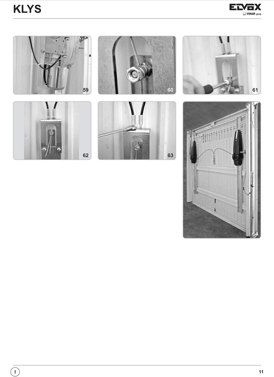
12 SBLOCCO INTERNO A MANIGLIA KLYS 9CD viene normalmente fornito con una maniglia di sblocco azionabile dall interno dell abitazione (Fig. 48). In caso di mancanza di energia elettrica ruotare entrambe le maniglie degli operatori. Se lo sblocco è a destra ruotare in senso antiorario per sbloccare il riduttore e aprire la porta manualmente (in caso di operatori con sblocco a sinistra ruotare la maniglia in senso orario). Per bloccare il riduttore riportare la maniglia nella posizione iniziale. Per poter eseguire in modo sicuro la movimentazione manuale dell anta occorre verificare che: - sulla porta siano fornite maniglie idonee; - tali maniglie siano posizionate in modo da non creare punti di pericolo durante il loro utilizzo; - lo sforzo manuale per muovere la porta non superi i 225 N per le porte poste su siti privati ed i N per le porte poste su siti commerciali ed industriali (valori indicati nel punto della norma EN 12453). ATTENZIONE : L attivazione dello sblocco può provocare un movimento non controllabile della porta in caso questa non sia correttamente equilibrata. In questo caso è necessario bilanciare correttamente la porta basculante SBLOCCO A FILO Con questo tipo di sblocco è possibile sbloccare i motori dall esterno in caso di black-out. E quindi consigliato quando non si hanno altri accessi al garage se non dalla porta basculante. Lo sblocco a filo può essere installato a DX o a SX dell operatore a seconda di dove si trova la maniglia di chiusura manuale della basculante. Il dispositivo di sblocco (cod. EBS2) viene applicato alla serratura esistente sulla porta basculante. Per il montaggio vedere le istruzioni specifiche inserite nell accessorio. Seguire le immagini dalla Fig. 53 alla I

13 I 11
14 SBLOCCO CHIAVE A BRUGOLA CON SERRATURA E possibile effettuare lo sblocco dall esterno, utilizzando l accessorio cod. EBS3 con chiave personalizzata. Per il montaggio vedere le istruzioni specifiche inserite nell accessorio. Per effettuare l operazione di sblocco dall esterno eseguire queste semplici operazioni: - Togliere il tamburo della serratura con apposita chiave (Fig. 66). - Inserire una chiave a brugola n 6 nel foro della piastrina fino a raggiungere la boccola di sblocco (Fig. 67). - Ruotare la chiave esagonale nel senso indicato dall adesivo applicato sulla basculante, fino ad ottenere lo sblocco dell operatore (Fig. 68). - Per bloccare il riduttore ruotare la chiave esagonale nel senso indicato dall adesivo applicato sulla basculante (Fig. 68) KLYS 9CD DESTRO KLYS 9CD SINISTRO 67 SBLOCCO SBLOCCO 68 ATTENZIONE! Il riaggancio dei vari sblocchi a porta chiusa non garantisce la totale chiusura della basculante, che rimarrà parzialmente aperta fino a quando non sarà eseguita una movimentazione elettrica. La corretta chiusura avverrà solamente a chiusura elettrica completata. MANUTENZIONE Da effettuare solamente da parte di personale specializzato dopo aver tolto l alimentazione elettrica al motore. Ogni anno ingrassare i cardini, le guide di scorrimento dei contrappesi, le leve telescopiche. 12 I
.")
15 COLLEGAMENTI ELETTRICI SLAVE CARD SICUT SLAVE SLAVE CARD SICUT MASTER COLLEGAMENTI TRA MOTORE MASTER E MOTORE SLAVE Tramite la scheda SLAVE è possibile comandare un 2 motore per applicazioni su basculanti con metrature superiori ai 9 m 2. Dopo aver tolto l alimentazione di rete dall impianto, è sufficiente inserire la scheda SLAVE nel connettore J10. La scheda si configura automaticamente all accensione per il pilotaggio di 2 motori. Collegare i 4 fili (sez. min. 0,5 mm 2 ) dei morsetti della scheda del motore MASTER ai morsetti presenti nel contenitore a bordo del motore SLAVE. Collegare i fili motore (sez. min. 1,5 mm 2 ) dei morsetti della scheda SLAVE ai morsetti e della morsettiera presente nel contenitore a bordo del motore SLAVE. SICUREZZA PER PORTA PEDONALE - PEDESTRIAN SECURITY (morsetti 5-6) Nel caso la basculante abbia una porta per passaggio pedonale, collegare un microinterruttore (N.C. a porta pedonale chiusa) che segnali alla centralina se la porta pedonale è aperta o chiusa. Il collegamento deve essere eseguito tra i morsetti 5-6 (se nessuna costa collegata), oppure in serie al contatto del bordo (se presente). Per un corretto funzionamento del sistema, il led DL3 deve essere acceso segnalando che la porta pedonale è correttamente chiusa. Se il led DL3 è spento non si avrà nessuna movimentazione della basculante perché la porta pedonale è aperta. se i morsetti 5-6 non vengono utilizzati da coste o altri dispositivi, eseguire un ponticello. 69 I 13
 dei morsetti 11-12-13-14 della scheda del motore MASTER ai morsetti 11-12-13-14 presenti nel contenitore a bordo del motore SLAVE. Collegare i fili motore (sez. min.")
16 OPTIONAL - Per i collegamenti ed i dati tecnici degli accessori attenersi ai relativi libretti di istruzione. SBLOCCO A FILO LEVE CURVE cod. EBS2 cod. EBX6 SBLOCCO CHIAVE A BRUGOLA CON SERRATURA LAMPEGGIATORE cod. EBS3 cod. ELA1/L CONTENITORE CON BATTERIE FOTOCELLULE cod. EBB1 cod. EFA1 CARICA BATTERIE KLYS 9CD 24 V SELETTORE A CHIAVE TELECOMANDO cod. ECB3 cod. EDS1 cod. ETR5 14 I

17 DICHIARAZIONE CE DI CONFORMITA (Dichiarazione di incorporazione di quasi-macchine allegato IIB Direttiva 2006/42/CE) No. : ZDT Il sottoscritto, rappresentante il seguente costruttore Elvox SpA Via Pontarola, 14/a Campodarsego (PD) Italy dichiara qui di seguito che i prodotti ATTUATORI PER BASCULANTI - SERIE KLYS Articoli KLYS 9CD risultano in conformità a quanto previsto dalla(e) seguente(i) direttiva(e) comunitaria(e) (comprese tutte le modifiche applicabili) e che sono state applicate tutte le seguenti norme e/o specifiche tecniche: Direttiva BT 2006/95/CE: EN (2004) Direttiva EMC 2004/108/CE: EN (2007), EN (2007) + A1 (2011) EN (2005), EN (2007) + A1 (2011) Direttiva R&TTE 1999/5/CE: EN (2002), EN (2000) Direttiva Macchine 2006/42/CE EN (2003) + A1 (2011), EN (2000) Dichiara inoltre che la messa in servizio del prodotto non deve avvenire prima che la macchina finale, in cui deve essere incorporato, non è stata dichiarata conforme, se del caso, alle disposizioni della Direttiva 2006/42/CE. Dichiara che la documentazione tecnica pertinente è stata costituita da Elvox SpA, è stata compilata in conformità all allegato VIIB della Direttiva 2006/42/CE e che sono stati rispettati i seguenti requisiti essenziali: 1.1.1, 1.1.2, 1.1.3, 1.1.5, 1.1.6, 1.2.1, 1.2.2, 1.2.6, 1.3.1, 1.3.2, 1.3.3, 1.3.4, 1.3.7, 1.3.8, 1.3.9, 1.4.1, 1.4.2, 1.5.1, 1.5.2, 1.5.4, 1.5.5, 1.5.6, 1.5.7, 1.5.8, 1.5.9, , 1.6.2, 1.7.1, 1.7.2, 1.7.3, 1.7.4, Si impegna a presentare, in risposta ad una richiesta adeguatamente motivata delle autorità nazionali, tutta la necessaria documentazione giustificativa pertinente al prodotto. Campodarsego, 06/05/2013 L Amministratore Delegato Nota: Il contenuto di questa dichiarazione corrisponde a quanto dichiarato nell ultima revisione della dichiarazione ufficiale disponibile prima della stampa di questo manuale. Il presente testo è stato adattato per motivi editoriali. Copia della dichiarazione originale può essere richiesta a Elvox SpA I 15
 Direttiva EMC 2004/108/CE: EN 61000-6-1 (2007), EN 61000-6-3 (2007) + A1 (2011) EN 61000-6-2 (2005), EN 61000-6-4 (2007) +")
18 IMPORTANT INSTRUCTIONS FOR THE SAFETY ATTENTION - FOR THE SAFETY OF PEOPLE IT IS IMPORTANT TO FOLLOW ALL THE INSTRUCTIONS KEEP THESE INSTRUCTIONS WITH CARE 1 - If it is not forecast in the electric gearcase, install a switch of magnetothermic type upstream, (omni polar with minimum port of the contacts of 3mm) with a check of conformity to the international standards. Such devise must be protected against the accidental lockup (for example by installing inside a locked board). 2 - For the section and the type of the cables ELVOX advices to use a cable of H05RN-F type with 1,5 sqmm minimum section and, however, to keep to the IEC 3120 and installation standards in force in your country. 3 - Positioning of a possible couple of photoelectric cells: the radius of the photoelectric cells must be at a height of no more than 70 cm from the ground and at a distance not superior to 20 cm from the motion plane of the door. Their correct working must be verified at the end of the installation in accordance with point of the EN To fulfil the limits set by EN 12453, and in case the peak force exceeds the normative limit of 400 N it is necessary to have recourse to the active presence survey on the whole height of the door (up to max 2,5 m) - The photoelectric cells, in this case, must be applied to the outside and the inside to a distance from the plan of movement of the door not advanced to 20 cm, every cm for all the height of the door until to a maximum of 2,5 m (EN point ) N.B.: The earthing of the system is obligatory. The data described in this handbook are purely a guide. ELVOX reserves the right to change them in any moment. Carry out the system in the respect of the standards and laws in force. IMPORTANT SAFETY INSTRUCTIONS FOR THE INSTALLATION ATTENTION - THE INCORRECT INSTALLATION CAN CAUSE SERIOUS DAMAGES FOLLOW ALL INSTALLATION INSTRUCTIONS 1 - This handbook is exclusively addressed to the specialized personnel who knows the constructive criteria and the protection devices against the accidents for motorized gates, doors and main doors (follow the standards and the laws in force). 2 - The installer will have to issue a handbook to the final user in accordance with the The installer will have to put the tags warning against the entrapping dangers near the controls and the horizontally pivoted door. 4 - Check frequently the system, in particular cables, springs and supports to find out possible unbalances, wear signs or damages. The final user must not operate electrically the horizontally pivoted door if this needs maintenance or repair, since a failure in the installation or a non correctly balanced barrier can provoke wounds. 5 - Before proceeding with the installation, the installer must forecast the risks analysis of the final automatized closing and the and the safety of the identified dangerous points (Following the standards EN 12453/EN 12445). 6 - Before installing the motion motor, the installer must verify that the door is in good mechanical conditions and that it adequately opens and closes. 7 - The installer must install the member for the manual release at a height inferior to 1,8 m. 8 - The installer will have to remove possible impediments to the motorized motion of the door (eg. Door bolts, sliding bolts, door locks etc.) 9 - The installer will permanently have to put the tags warning against the deflection on a very visible point or near possible fixed controls The wiring harness of the different electric components external to the operator (for example photoelectric cells, flashlights etc.) must be carried out according to the EN and the modifications to it done in the point of the EN Keep the automatism controls (push-button panel, remote control etc.) out of the children way. The controls must be placed at a minimum height of 1,5 m from the ground and outside the range of the mobile parts Before carrying out any installation, regulation or maintenance operation of the system, take off the voltage by operating on the special magnetothermic switch connected upstream At the end of the installation, the installer will have to make sure that the parts of the door do not encumber streets or public sidewalks At the end of the installation, the installer will have to make sure that the motion motor prevents or blocks the opening motion when the door is loaded with a 20 kg weight, fixed in the middle of the inferior edge of the door. THE ELVOX COMPANY DOES NOT ACCEPT ANY RESPONSIBILITY for possible damages caused by the non observance during the installation of the safety standards and of the laws in force at present. Directive 2002/96/EC (WEEE) The crossed-out wheelie bin symbol marked on the product indicates that at the end of its useful life, the product must be handled separately from household refuse and must therefore be assigned to a differentiated collection centre for electrical and electronic equipment or returned to the dealer upon purchase of a new, equivalent item of equipment. The user is responsible for assigning the equipment, at the end of its life, to the appropriate collection facilities. Suitable differentiated collection, for the purpose of subsequent recycling of decommissioned equipment and environmentally compatible treatment and disposal, helps prevent potential negative effects on health and the environment and promotes the recycling of the materials of which the product is made. For further details regarding the collection systems available, contact your local waste disposal service or the shop from which the equipment was purchased. Risks connected to substances considered as dangerous (WEEE). According to the WEEE Directive, substances since long usually used on electric and electronic appliances are considered dangerous for people and the environment. The adequate differentiated collection for the subsequent dispatch of the appliance for the recycling, treatment and dismantling (compatible with the environment) help to avoid possible negative effects on the environment and health and promote the recycling of material with which the product is compound. 16 EN

19 TECHNICAL DATA / INSTALLATION KLYS 9CD SLAVE Doors of max. max 12 / 0,47 m 2 /in 2 EBM1 EBM2 EBX7 EBX1 EBX4 EBX2 EBX6 No. 1 - EBM1 No. 1 - EBM2 No. 1 - EBX7 No. 1 - EBX1 No. 1 - EBX4 No. 1 - EBX2 - Right-hand side KLYS 9CD MASTER with limit switches, without mounting plate - Right-hand side KLYS 9CD SLAVE without mounting plate - Mounting plate L = 1,95 m for manual up-and-over applications - Mounting plate L = 0,8 m for automated up-and-over applications - Lateral transmission for 2 operators L = 30 cm - Pair of straight levers (or EBX6 - pair of curved levers). TECHNICAL FEATURES 1950 / 76,83 (long mounting plate) 800 / 31,52 (short mounting plate) 703 / 27,698 KLYS 9CD is an irreversible operator employed for counterweight up-andover garage doors. The system comprises a reducer unit, lubricated with synthetic grease, a manual release device in the absence of a power supply, and mounting plate (optional) to fasten the operator to the tilting roller device. IP44 series protection safeguards KLYS 9CD against any sprays of water from any direction. KLYS 9CD SLAVE, paired with KLYS 9CD MASTER, is equipped with an LED lamp, speed adjustment control and impact sensor in compliance with European legislation currently in force. TECHNICAL DATA Door lever s max. length Max door surface Max door width Max. door height Max. torque 1 motor Operator RPM KLYS 9CD MASTER + KLYS 9CD SLAVE cm 83 m 2 12 (2 motors) m 6 (2 motors) m 2,5 Nm 350 rpm 1,8 102/4, / 7,171 69,5/2, / 5,792 Adjustable opening time Power supply Motor power supply s V ~ 50 Hz 24 Vdc Power of 1 motor W 55 Main line absorption A 1,2 Daily cycles suggested n 36 Service 80 % Actuator weight kg 9,5 MASTER - 8 SLAVE Noise db <70 Measurements in mm/in 1 Operating temperature C C Protection grade IP 44 EN 17
 800 / 31,52 (short mounting plate) 703 / 27,698 KLYS 9CD is an irreversible operator employed for counterweight up-andover garage doors.")
20 The door lever s length cannot exceed the 83 cm KLYS 9CD MASTER operator + 1 KLYS 9CD SLAVE operator 2 - Aerial 3 - Blinker 4 - key selector 5 - Safety edge 6 - Photoelectric cells (internal) PRE-INSTALLATION CHECK For doors with a total width up to 6 m or a total surface area of 12 square metres, 2 KLYS 9CD (MASTER EBM1 + SLAVE EBM2) device should be used; mounted as shown in Fig. 3, with a PAIR OF STRAIGHT LEVERS code EBX2 (or a PAIR OF CURVED LEVERS code EBX6), the accessories for LATERAL TRANSMISSION for 2 operators cod. EBX4 and 2 SHORT MOUNTING PLATE codes EBX1 or 2 LONG MOUNTING PLATE codes EBX7. - Check that the available space between the moving frame of the door and external frame with counterweights exceeds 15 mm. If so, the STRAIGHT LEVERS can be mounted. Otherwise, mount the CURVED LEVERS if the distance is less than 15 mm, making sure to remain within the assembly parameters described in Fig Check that the up-and-over door slip bearings are not blocked or obstructed and that the counterweight fastening cables are in correct working order. - Remove, if present, the manual closing lever connected to the locking device. N.B. It is obligatory to uniform the characteristics of the door to the standards and laws in force. The door can be automatized only if in a good state and if in accordance with EN standard. No trapping points must be generated (for example between horizontally pivoted open door and wall). PARTS TO INSTALL MEETING THE EN STANDARD COMMAND TYPE USE OF THE SHUTTER Skilled persons Skilled persons Unrestricted use (out of a public area*) (public area) with manned operation A B - with visible impulses (e.g. sensor) with not visible impulses (e.g. remote control device) C or E C or E C and D, or E C or E C and D, or E C and D, or E automatic C and D, or E C and D, or E C and D, or E * a typical example are those shutters which do not have access to any public way. A: Command button with manned operation (that is, operating as long as activated), B: Key selector with manned operation, like code EDS1. C: Adjustable power of the motor. D: Safety edges and/or other safety devices to keep thrust force within the limits of EN12453 regulation - Appendix A. E: Photocells, like code EFA1 (To apply every cm for all the height of the column of the gate up to a maximum of 2,5 m - EN point ) EN

21 INSTALLATION OF 2 MOTOR KLYS 9CD ON DOORS UP TO 12 m 2 LEVER APPLICATION 35 mm 55 mm ANGLE IRONS LEVERS SLEEVE ANGLE IRONS LEVERS SLEEVE 4 40 mm 5A 5B ASSEMBLY OF PAIR OF STRAIGHT LEVERS (code EBX2) BETWEEN MOTOR AND UPPER DOOR FRAME N.B.: THE PAIR OF STRAIGHT TELESCOPIC LEVERS can be mounted when there is a 15 mm minimum space guaranteed between the moving part of the door and the exterior door frame containing the counterweight. - Rivets or screws should be used to fix corner parts to the upper frame, in line with measurements shown in Fig. 4: if at the measurement of 35 mm, one finds the reinforcing plate of the door frame, it is possible to fix the brackets directly above this reinforcing plate even if the measurement will not be maintained. In the event that the up-and-over door is already pre-fitted for automated movement, use the attachments provided. Do not use the angles provided. - Insert the sliding arm sleeve into the angles and secure the pivots and split pins (Fig. 4). - Make sure that the casing does not touch the up-and-over door movement levers when mounted. ASSEMBLY OF PAIR OF CURVED LEVERS (code EBX6) BETWEEN MOTOR AND UPPER DOOR FRAME N.B.: The PAIR OF CURVED TELESCOPIC LEVERS should be mounted when there is less than the 15 mm minimum space guaranteed between the moving part of the door and the exterior door frame containing the counterweight. - In the event that the up-and-over door is already pre-fitted for automated movement, use the attachments provided. Do not use the angles provided. - Insert the sliding arm sleeve into the angles and secure the pivots and split pins (Fig. 4). - Make sure that the casing does not touch the up-and-over door movement levers when mounted. Note: The length of the sleeve and of the sliding arm must be modified in function of overhead door height. Trim the sleeve and the sliding arm so that the sleeve rests 40 mm from the center of the drawbar pivot pin and the sliding arm avoids contact with the rotating dowels located on the angles (Fig. 5A) LONG MOUNTING PLATE (FOR NON-AUTOMATED UP-AND- OVER DOORS) Code EBX7 Position the mounting plate with the upper section (slotted hole to feed electric cable) in top position (Fig. 6). Fix the mounting spar flush against the upper moving part of the up-andover door distance of 17 cm from the internal cable of the sheath using 6.3 x 13 self-tapping screws (not included). 17 cm SHORT MOUNTING PLATE (FOR AUTOMATED UP-AND- OVER DOORS) Code EBX1 Calculate the length, L = C [mm], to which the mounting plate should be vertically fixed (Fig. 7-8). Position it on the appropriate vertical supports while keeping the upper part (slotted hole to feed electric cable) in a vertical position facing upwards. Fix the mounting plate distance of 17 cm from the internal cable of the sheath using the four feedthrough holes, four 4 metric screws (M6x25) and self-locking nuts (not supplied). max 83 cm C L L L = C mm After the assembly s completion, either with the LONG MOUNTING PLATE or with the SHORT MOUNTING PLATE, the reducer s outlet-shaft must be placed in a distance of 80±10 mm from the pivot-axle of the up-andover door s little arm. EN 19
22 OPERATORS ASSEMBLY - Fix KLYS 9CD to the mounting plate using the screws supplied (Fig ). - Check the balance of the up-and-over door. If incorrect, and in the event that the doors are not motor-driven, add 9 kg to each counterweight in order to achieve the correct balance. POSITIONING OF THE SQUARE DRIVING SHAFT ON THE OPERATORS - Insert the square driving shaft into the operator take-off shaft end (Fig. 13) RE-BALANCING OF THE DOOR When installing 2 KLYS 9CD operator on a door, 9 kg extra each side must be applied on the existing counterweights. 20 EN
23 CORNER TRACK BLOCK FIXING - 2 MOTORS (Code EBX4) - Insert the bushing with locking pins for both sides of the square driving shaft 20 x 20 (Fig. 14). - Fix the adjustable support angle bars to the moveable up-and-over door frame in line with the square driving shaft (Fig. 15). WARNING: fastening screws not supplied. - Insert bushings in the supports (Fig. 16), bolt the support structures into place (Fig. 17). - Check that the STRAIGHT LEVERS (code EBX2) are perfectly perpendicular and do not touch the counterweight casing or moving door parts. The PAIR OF CURVED LEVERS (code EBX6) should be mounted when there is less than the 15 mm minimum space guaranteed between the moving part of the door and the exterior door frame containing the counterweight (while aligned with measurements described in Fig. 4) EN 21
24 CORNER TRACK BLOCK TUBING AND LEVER FIXING - Insert the lever into the sleeve and the welded bushing into the square driving shaft (Fig. 18). - Begin to lock the pins positioned on the track shaft into position (Fig ) on the centring bush and relative lock nuts (Fig. 21). - Fix the lever to the tubing tight with locking pin and lock nut (Fig ). - With the help of the handles inserted in the relative realease mecanism, mechanically release the operators (Fig ) - Verify the correct movement of the door and then lock the motors again. - Lubricate the door s levers and guides EN
25 ELECTRICAL CONNECTION Once you have removed the covers of the control panel boxes both on the Master and on the Slave motors (pict 26), insert the SLAVE control panel onto the MASTER control panel inside the MASTER operator (Fig ) inserting the spacer support in the appropriate hole (Fig. 30). Carry out the electrical connection as shown in Fig. 69 in order to check dead man s switch control to up-and-over door commands. WARNING: IPX4 can only be guaranteed by mounting the rubber cable fairleads in the electrical switchboard into the relative container holes (Fig. 27) and the rounded slotted wire seal on the cover latch (Fig. 28) ELECTRICAL CABLE FIXING SIDE MASTER OPERATOR The electrical cable that powers the operator should be fixed to the telescopic lever using the plastic bands shown in Fig. 29. The cable should be curved in order that it is not subject to twist, tension or tearing while the door is in movement. Cables exiting the door plate hole should be protected with some form of sheath to avoid their being cut during movement LIMIT SWITCHES ADJUSTMENT - MASTER OPERATOR - Position DIP 8 to ON and press the command button on the electrical switchboard (Fig. 31) to start up-and-over door movement. Release the button once the operation has been carried out. Slacken the holding screw for the green cam and turn until activating the microswitch (Fig. 34). - Tighten the green cam holding screw (Fig. 35). - Press the key on the electronic switchboard (Fig. 31) to close the up-andover door movement. Release the button once the closing operation has been completed. Slacken the holding screw for the red cam and turn until the microswitch is activated (Fig. 37). - Tighten the red cam holding screw (Fig. 38). - Carry out a complete opening and closing cycle to check that the cams are positioned perfectly. Correct positions if required. - Turn DIP8 to OFF. Refer to the section ELECTRICAL CONNECTIONS for connection to auxiliary units and switchboard functions. Close the electrical box with the appropriate cover using the 6 screws provided. DIP 8 SLAVE CARD SLAVE CARD EN 23
26 CLOSURE LIMIT SWITCHES RED CAM OPENING LIMIT SWITCHES GREEN CAM 32 OPENING LIMIT SWITCHES ADJUSTMENT CLOSURE LIMIT SWITCHES ADJUSTMENT EN
27 CASING MOUNTING - Mount the fixed handle (without release warning) on the casing using the screws, bolt and washer supplied, inserting them on the opposite side to the release device (Fig. 39). - Apply the cap on the side of the operator where the driving shaft if not sticking out (pitc 46). - Connect the illuminator unit connector to the cable leading from the electrical switchboard (Fig. 40 and 41). - Insert the casing on the reducer, making sure to position it on the mounting plate in the appropriate position and centre the release spar with the predrilled holes on the casing. Fasten the casing to the motor with the screws supplied (Fig. 43 and 44) and then fix the release device handle (Fig. 45) to the motor release device spar. - Apply the lateral cap. The operator is now installed and ready to carry out tutoring programme operations (refer to PROGRAMMING section) EN 25
28 INTERNAL RELEASE DEVICE HANDLE KLYS 9CD is generally supplied with a manual release device handle that can be operated from inside the premises (Fig. 48). In the event of power failure turn both the handles of the operators. If the release mechanism is positioned to the right turn the right-hand-side handle anticlockwise (with operators with release on the left hand side, turn the handle clock wise). This will unlock the reducer and allow the door to be opened manually. Turn the handle back to its original position in order to block the reducer. In order to carry out the manual movement of the spar safely, it is important to check that: - The door is supplied with suitable handles. - Handles are positioned in such a way so as not to create hazard points during their use The manual effort required to move the door should not exceed 225 N for doors installed for private use and 390 N for doors for commercial or industrial use (parameters set by item of EN standard). WARNING: The release mechanism may cause the door to move in an unpredictable fashion if the door has not been correctly centred and balanced. In such cases, it is necessary to carry out the necessary balancing operations to the up-and-over doors CABLE UNLOCKING RELEASE With such type of release system, in case of black outs, it is possible to release the motors from the outside. It is therefore advisable, when the garage door is the only possible way of access. The cable unlocking release can be installed either to the left or right of the operator depending on the position of the locking handle of the garage door. The release device (code EBS2) is mounted on the existing locking apparatus installed on the up-and-over door. ATTENTION: in case of 2 locks on the door, fit for each lock unlocking release EBS1. For the assembly see the accessory specific instructions. Follow the instructions described from Fig. 53 to EN
29 EN 27
30 ALLEN KEY LOCK UNLOCKING RELEASE It is also possible to release the locking device from the outside using auxiliary device code EBS3 and customised key. For the assembly see the accessory specific instructions. Follow the simple operations described below in order to carry out unlocking operations: - Remove the lock barrel with the appropriate key (Pic. 66). - Insert an allen wrench (no. 6) in the hole of the plate as far as the release device bushing (Pic. 67). - Turn the hexagonal key in the direction indicated on the sticker on the up-and-over door until the operator unlocking device is activated (Pic. 68). - In order to lock the reducer, turn the hexagonal key in the direction indicated on the sticker on the up-and-over door (Pic. 68) RIGHT KLYS 9CD LEFT KLYS 9CD 67 RELEASE RELEASE 68 ATTENTION! The coupling of the releases with closed door doesn t guarantee the total closing of the door. It will partially remain opened until an electrical movement. The corrected closing will only happen with electrical closing completed. MAINTENANCE To be undertaken only by specialized staff after disconnecting power supply. Grease the fulcrums, the counterweight channels, the telescopic levers and carry out the necessary impacts force check as for EN12345 and EN12445 once a year. 28 EN
31 ELECTRIC CONNECTIONS SLAVE CARD SICUT SLAVE SLAVE CARD SICUT MASTER WIRING CONNECTIONS BETWEEN MASTER AND SLAVE MOTORS SLAVE card allows users to operate a second motor on up-and-over doors with a surface area exceeding 9 square metres. Switch off the power supply to the system and insert the slave board into the J10 connector. The board will be automatically configured once the system is switched back on preset for 2 motors. Connect the 4 wires (min. diam. 0,5 mm 2 ) from the contacts of the Master control panel to the contacts on the SLAVE control panel. Connect the motor wires (min. diam. 1,5 mm 2 ) from the contacts of the SLAVE control panel to the contacts - and + available in the box on the motor slave. PEDESTRIAN SECURITY (terminals 5 ad 6) In the event that the main up-and over-doors are also equipped with pedestrian access, connect a microswitch (N.C. closed pedestrian access door) to signal to the control panel that the pedestrian door is open or closed. Connection should be carried out using terminals 5 and 6 (where no safety strips are connected), or, where present, in safety strip contact series. To ensure correct system operations, the DL3 LED lamp should be illuminated, signalling that the pedestrian door is closed correctly. If the led DL3 is OFF, the movement of the garage door will not be possible, because the pedestrian door is open. NOTE: Create a jumper if terminals 5 and 6 are not used by safety strips or other devices. 69 EN 29
TECHNICAL MANUAL FT GEN 17
 IT MANUALE TECNICO EN TECHNICAL MANUAL FR MANUEL TECHNIQUE FT GEN 7 3 4 5 6 Schede opzionali Art. 5733 e Art. 5734 per Monitor serie Bravo Optional cards Art. 5733 and Art. 5734 for Bravo series Monitor
Fabricant. 2 terminals
 Specifications Fabricant Nominal torque (Nm) 65 Minimal torque (Nm) 0,63 Coil resistance - 20 C (ohms) 20 Rated current DC (A) 1 Rotor inertia (kg.m 2 ) 2.10-3 Weight (kg) 7,20 Heat dissipation continuous
Contrôle d'accès Access control. Notice technique / Technical Manual
 p.1/18 Contrôle d'accès Access control INFX V2-AI Notice technique / Technical Manual p.2/18 Sommaire / Contents Remerciements... 3 Informations et recommandations... 4 Caractéristiques techniques... 5
Notice Technique / Technical Manual
 Contrôle d accès Access control Encodeur USB Mifare ENCOD-USB-AI Notice Technique / Technical Manual SOMMAIRE p.2/10 Sommaire Remerciements... 3 Informations et recommandations... 4 Caractéristiques techniques...
03/2013. Mod: WOKI-60IP/TR. Production code: DTWIC 6000
 03/2013 Mod: WOKI-60IP/TR Production code: DTWIC 6000 ENCASTRABLE INDUCTION DROP IN INDUCTION 11/2011 TECHNICAL FEATURES DOCUMENTATION S.A.V. Notice d utilisation : FX00326-A Guide d intervention : ---
SPEZZATRICE AUTOMATICA PRESSABURRO ITALIAN BAKERIES MACHINERY AUTOMATIC BUTTER PRESSING MACHINE MACHINE AUTOMATIQUE PRESSE-BEURRE LA PÂTE
 SPEZZATRICE AUTOMATICA PRESSABURRO ITALIAN BAKERIES MACHINERY AUTOMATIC BUTTER PRESSING MACHINE MACHINE AUTOMATIQUE PRESSE-BEURRE LA PÂTE ITALIAN BAKERIES MACHINERY PRESSABURRO VERNICIATA BUTTER PRESSING
Folio Case User s Guide
 Fujitsu America, Inc. Folio Case User s Guide I N S T R U C T I O N S This Folio Case is a stylish, lightweight case for protecting your Tablet PC. Elastic Strap Pen Holder Card Holders/ Easel Stops Figure
Thank you for choosing the Mobile Broadband USB Stick. With your USB Stick, you can access a wireless network at high speed.
 Thank you for choosing the Mobile Broadband USB Stick. With your USB Stick, you can access a wireless network at high speed. Note: This manual describes the appearance of the USB Stick, as well as the
Lavatory Faucet. Instruction Manual. Questions? 1-866-661-9606 customerservice@artikaworld.com
 Lavatory Faucet Instruction Manual rev. 19-01-2015 Installation Manual You will need Adjustable Wrench Adjustable Pliers Plumber s Tape Hardware list (included) Allen Key Socket wrench tool Important Follow
R.V. Table Mounting Instructions
 PTSS165 ACCESSORY MOUNTING INSTRUCTIONS Use these instructions in conjunction with your main manual to properly assemble your gas grill. Refer to the main manual for safety, operating, cleaning and maintenance
Paxton. ins-20605. Net2 desktop reader USB
 Paxton ins-20605 Net2 desktop reader USB 1 3 2 4 1 2 Desktop Reader The desktop reader is designed to sit next to the PC. It is used for adding tokens to a Net2 system and also for identifying lost cards.
WINTER BOAT STORAGE SYSTEM SYSTÈME DE REMISAGE HIVERNAL POUR BATEAU
 MANUAL / MANUEL VIDEO WINTER BOAT STORAGE SYSTEM SYSTÈME DE REMISAGE HIVERNAL POUR BATEAU ASSEMBLY INSTRUCTIONS GUIDE D ASSEMBLAGE NAVIGLOO 14-18½ ft/pi FISHING BOAT! RUNABOUT! PONTOON BOAT! SAILBOAT (SAILBOAT
Warning: Failure to follow these warnings could result in property damage, or personal injury.
 Western Steel & Tube 1 Storage Locker Extended Storage Locker Storage Cabinet Assembly And Use Instructions Warning: Failure to follow these warnings could result in property damage, or personal injury.
Important information. New SIMATIC HMI Panels. Migration made easy start now. SIMATIC HMI Panels. siemens.com/simatic-panels
 Important information New SIMATIC HMI Panels Migration made easy start now SIMATIC HMI Panels siemens.com/simatic-panels Totally Integrated Automation Portal (TIA Portal) est l environnement d ingénierie
GIGABIT PCI DESKTOP ADAPTER DGE-530T. Quick Installation Guide+ Guide d installation+
 GIGABIT PCI DESKTOP ADAPTER Quick Installation Guide+ Guide d installation+ Check Your Package Contents Quick Installation Guide Gigabit Ethernet PCI Adapter CD with Manual and Drivers DO NOT insert the
Informazioni su questo libro
 Informazioni su questo libro Si tratta della copia digitale di un libro che per generazioni è stato conservata negli scaffali di una biblioteca prima di essere digitalizzato da Google nell ambito del progetto
A propos de ce livre. Consignes d utilisation
 A propos de ce livre Ceci est une copie numérique d un ouvrage conservé depuis des générations dans les rayonnages d une bibliothèque avant d être numérisé avec précaution par Google dans le cadre d un
Instructions Mozilla Thunderbird Page 1
 Instructions Mozilla Thunderbird Page 1 Instructions Mozilla Thunderbird Ce manuel est écrit pour les utilisateurs qui font déjà configurer un compte de courrier électronique dans Mozilla Thunderbird et
Z-Axis Compliance Device Compliance en z
 Compensation for different vertical positions Collision recognition in Z-direction Protection of parts and work pieces Monitoring of the insertion forces during assembly operations Monitoring of the picking
APPENDIX 6 BONUS RING FORMAT
 #4 EN FRANÇAIS CI-DESSOUS Preamble and Justification This motion is being presented to the membership as an alternative format for clubs to use to encourage increased entries, both in areas where the exhibitor
How to Login to Career Page
 How to Login to Career Page BASF Canada July 2013 To view this instruction manual in French, please scroll down to page 16 1 Job Postings How to Login/Create your Profile/Sign Up for Job Posting Notifications
We create intelligent doors
 We create intelligent doors A U T O M A T I C S L I D I N G D O O R S NEW SOLUTIONS, is the new innovation. This is our mission. Create and design new solutions to allow people to optimize their time NUOVE
that the child(ren) was/were in need of protection under Part III of the Child and Family Services Act, and the court made an order on
 was/were in need of protection under Part III of the Child and Family Services Act, and the court made an order on") ONTARIO Court File Number at (Name of court) Court office address Applicant(s) (In most cases, the applicant will be a children s aid society.) Full legal name & address for service street & number, municipality,
ONTARIO Court File Number at (Name of court) Court office address Applicant(s) (In most cases, the applicant will be a children s aid society.) Full legal name & address for service street & number, municipality,
Sécurité relative aux sièges auto et aux rehausseurs
 Sécurité relative aux sièges auto et aux rehausseurs Safety with Car Seats and Booster Seats Car crashes are the main cause of accidental death and serious injury of children. Correctly using a car or
POLICY: FREE MILK PROGRAM CODE: CS-4
 POLICY: FREE MILK PROGRAM CODE: CS-4 Origin: Authority: Reference(s): Community Services Department Cafeteria Services and Nutrition Education Division Resolution #86-02-26-15B.1 POLICY STATEMENT All elementary
TABLE DES MATIERES A OBJET PROCEDURE DE CONNEXION
 1 12 rue Denis Papin 37300 JOUE LES TOURS Tel: 02.47.68.34.00 Fax: 02.47.68.35.48 www.herve consultants.net contacts@herve consultants.net TABLE DES MATIERES A Objet...1 B Les équipements et pré-requis...2
Garage Door Monitor Model 829LM
 Garage Door Monitor Model 829LM To prevent possible SERIOUS INJURY or DEATH from a closing garage door: NEVER permit children to operate or play with door control push buttons or remote control transmitters.
Contents Windows 8.1... 2
 Workaround: Installation of IRIS Devices on Windows 8 Contents Windows 8.1... 2 English Français Windows 8... 13 English Français Windows 8.1 1. English Before installing an I.R.I.S. Device, we need to
SA-32 / SA-62 INSTRUCTION MANUAL - MANUEL D INSTRUCTIONS
 SA-32 / SA-62 INSTRUCTION MANUAL - MANUEL D INSTRUCTIONS 4 5 6 7 4 5 6 7 1. Telephone Paging Volume Control 1. Contrôle de volume Paging Téléphone 2. Microphone Volume Control 2. Contrôle volume du microphone
ASSEMBLY INSTRUCTIONS DIRECTIVES POUR L'ASSEMBLAGE ombre pendant lamp lampe suspendue à tons dégradés, chocolat
 ASSEMBLY INSTRUCTIONS DIRECTIVES POUR L'ASSEMBLAGE ombre pendant lamp lampe suspendue à tons dégradés, chocolat SKU 2728089 INSTRUCTIONAL MANUAL MANUEL D'INSTRUCTIONS 270/2707 COMPONENT LIST LISTE DES
ASSEMBLY INSTRUCTIONS DIRECTIVES POUR L'ASSEMBLAGE luster chandelier lamp chandelier à trois branches en verre lustré
 ASSEMBLY INSTRUCTIONS DIRECTIVES POUR L'ASSEMBLAGE luster chandelier lamp chandelier à trois branches en verre lustré SKU 2711592 INSTRUCTIONAL MANUAL MANUEL D'INSTRUCTIONS 270/2707 COMPONENT LIST LISTE
Guide d'installation rapide TFM-560X YO.13
 Guide d'installation rapide TFM-560X YO.13 Table of Contents Français 1 1. Avant de commencer 1 2. Procéder à l'installation 2 Troubleshooting 6 Version 06.08.2011 16. Select Install the software automatically
Contrôle d accès Access control MOD-TCPIP-AI. Notice technique / Technical Manual
 Contrôle d accès Access control MOD-TCPIP-AI Notice technique / Technical Manual Notice technique Mod-TCPIP-AI 9 septembre 2008 v.1.0 p.2/16 Sommaire / Contents Sommaire / Contents...2 Remerciements...3
DOCUMENTATION - FRANCAIS... 2
 DOCUMENTATION MODULE SHOPDECORATION MODULE PRESTASHOP CREE PAR PRESTACREA INDEX : DOCUMENTATION - FRANCAIS... 2 INSTALLATION... 2 Installation automatique... 2 Installation manuelle... 2 Résolution des
SYSTÈME JETS D AIR WISH WISH AIR JETS SYSTEM Système de massage à jets d air pour bains en polymère - Air jet massage system for polymer bathtubs
 SYSTME JETS D AIR WISH WISH AIR JETS SYSTEM Système de massage à jets d air pour bains en polymère - Air jet massage system for polymer bathtubs Manuel d installation - Installation manual 6835, RUE PICARD
WEB page builder and server for SCADA applications usable from a WEB navigator
 Générateur de pages WEB et serveur pour supervision accessible à partir d un navigateur WEB WEB page builder and server for SCADA applications usable from a WEB navigator opyright 2007 IRAI Manual Manuel
Mesure chimique. Chemical measurement. Sonde de température Pt 1000 Inox Pt 1000 stainless steel. Ref : 703 262. Français p 1.
 Mesure chimique Chemical measurement Français p 1 English p 3 Sonde de température Pt 1000 Inox Pt 1000 stainless steel Version : 6010 Mesure chimique Sonde de température Pt 1000 Inox 1 Description La
Le No.1 de l économie d énergie pour patinoires.
 Le No.1 de l économie d énergie pour patinoires. Partner of REALice system Economie d énergie et une meilleure qualité de glace La 2ème génération améliorée du système REALice bien connu, est livré en
USB 598. Quick Start Guide (Windows) Guide de démarrage rapide (Windows) USB Modem. Modem USB. www.sierrawireless.com
 Guide de démarrage rapide (Windows) USB Modem. Modem USB. www.sierrawireless.com") USB 598 With Avec USB Modem Quick Start Guide (Windows) Modem USB Guide de démarrage rapide (Windows) www.sierrawireless.com This guide provides installation instructions for users of: Windows Vista Windows
USB 598 With Avec USB Modem Quick Start Guide (Windows) Modem USB Guide de démarrage rapide (Windows) www.sierrawireless.com This guide provides installation instructions for users of: Windows Vista Windows
Instructions pour mettre à jour un HFFv2 v1.x.yy v2.0.00
 Instructions pour mettre à jour un HFFv2 v1.x.yy v2.0.00 HFFv2 1. OBJET L accroissement de la taille de code sur la version 2.0.00 a nécessité une évolution du mapping de la flash. La conséquence de ce
Règlement sur le télémarketing et les centres d'appel. Call Centres Telemarketing Sales Regulation
 THE CONSUMER PROTECTION ACT (C.C.S.M. c. C200) Call Centres Telemarketing Sales Regulation LOI SUR LA PROTECTION DU CONSOMMATEUR (c. C200 de la C.P.L.M.) Règlement sur le télémarketing et les centres d'appel
Guide d installation Deco Drain inc. DD200
 Guide d installation Deco Drain inc. DD200 Pour plus informations et pour télécharger les guides d installation en couleur, visitez notre site web. www.decodrain.com Soutien technique : Composez le : 514-946-8901
ARP-090G / ARP-090K NOTICE D'EMPLOI INSTRUCTION MANUAL
 2 7 NOTICE D'EMPLOI INSTRUCTION MANUAL ARP-090G / ARP-090K Lire attentivement la notice avant d utiliser l appareil Before operating this product, please read user manual completely FRANCAIS EMPLACEMENT
Quick Installation Guide TEW-AO12O
 Quick Installation Guide TEW-AO12O Table of of Contents Contents Français... 1 1. Avant de commencer... 1 2. Installation du matériel... 2 3. Montage... 4 Troubleshooting... 6 Version 10.04.2007 1. Avant
First Nations Assessment Inspection Regulations. Règlement sur l inspection aux fins d évaluation foncière des premières nations CONSOLIDATION
 CANADA CONSOLIDATION CODIFICATION First Nations Assessment Inspection Regulations Règlement sur l inspection aux fins d évaluation foncière des premières nations SOR/2007-242 DORS/2007-242 Current to September
Stainless Steel Solar Wall Light
 V 2.9 Stainless Steel Solar Wall Light User Manual Please read and understand all instructions before use.retain this manual for future reference. V 2.9 Stainless Steel Solar Wall Light SPECIFICATIONS
MT 3500 MT 3500 C LaSER
 MT 3500 MT 3500 C LASER MT 3500 - MT 3500 C LASER 1. EquilibraTRiCE a DISPLay LCD - wheel balancer with LCD 2 display - EquilibreuSE à écran LCD ECRAN LCD Equilibratrice a display LCD ad elevate prestazioni
L azienda The firm L entreprise
 2014 L azienda The firm L entreprise Gensini Srl è una giovane azienda fortemente orientata all innovazione ed allo stesso tempo vanta una solida esperienza fine degli anni 60, all avvento nel che affonda
MONTEGO 3 PERSON CUSHION GARDEN SWING WITH CANOPY ASSEMBLY INSTRUCTIONS ITEM# SC-177-2GS
 MONTEGO 3 PERSON CUSHION GARDEN SWING WITH CANOPY ASSEMBLY INSTRUCTIONS ITEM# SC-177-2GS QUESTIONS, PROBLEMS, MISSING PARTS WITH THIS PRODUCT? DO NOT RETURN TO YOUR RETAILER, PLEASE CALL OUR CUSTOMER SERVICE
Nouveautés printemps 2013
 » English Se désinscrire de la liste Nouveautés printemps 2013 19 mars 2013 Dans ce Flash Info, vous trouverez une description des nouveautés et mises à jour des produits La Capitale pour le printemps
Propriétés de la matière. Material properties. Sonde de pression Pressure probe. Ref : 242 013. Français p 1. English p 3.
 Propriétés de la matière Material properties Français p 1 English p 3 Sonde de pression Pressure probe Version : 6010 Propriétés de la matière Sonde de pression 1 Principe et description 1.1 Principe La
Package Contents. System Requirements. Before You Begin
 Package Contents DWA-125 Wireless 150 USB Adapter CD-ROM (contains software, drivers, and manual) Cradle If any of the above items are missing, please contact your reseller. System Requirements A computer
Software and Hardware Datasheet / Fiche technique du logiciel et du matériel
 Software and Hardware Datasheet / Fiche technique du logiciel et du matériel 1 System requirements Windows Windows 98, ME, 2000, XP, Vista 32/64, Seven 1 Ghz CPU 512 MB RAM 150 MB free disk space 1 CD
Once the installation is complete, you can delete the temporary Zip files..
 Sommaire Installation... 2 After the download... 2 From a CD... 2 Access codes... 2 DirectX Compatibility... 2 Using the program... 2 Structure... 4 Lier une structure à une autre... 4 Personnaliser une
DOCUMENTATION - FRANCAIS... 2
 DOCUMENTATION MODULE CATEGORIESTOPMENU MODULE CREE PAR PRESTACREA INDEX : DOCUMENTATION - FRANCAIS... 2 INSTALLATION... 2 CONFIGURATION... 2 LICENCE ET COPYRIGHT... 3 SUPPORT TECHNIQUE ET MISES A JOUR...
GAME CONTENTS CONTENU DU JEU OBJECT OF THE GAME BUT DU JEU
 GAME CONTENTS 3 wooden animals: an elephant, a Polar bear and an African lion 1 Playing Board with two tree stumps, one red and one blue 1 Command Board double sided for two game levels (Green for normal
Natixis Asset Management Response to the European Commission Green Paper on shadow banking
 European Commission DG MARKT Unit 02 Rue de Spa, 2 1049 Brussels Belgium markt-consultation-shadow-banking@ec.europa.eu 14 th June 2012 Natixis Asset Management Response to the European Commission Green
PARIS ROISSY CHARLES DE GAULLE
 GPS 2 34 1 E 49 0 46 N GPS* 2 56 56 E 49 0 12 N Votre contact / Your contact: et / and: Accueil : Cabines téléphoniques publiques Reception: Public telephone kiosks Navette Shuttle AÉROPORT DE TT CAR TRANSIT
Lesson Plan Physical Descriptions. belle vieille grande petite grosse laide mignonne jolie. beau vieux grand petit gros laid mignon
 Lesson Plan Physical Descriptions Objective: Students will comprehend and describe the physical appearance of others. Vocabulary: Elle est Il est Elle/Il est Elle/Il a les cheveux belle vieille grande
Utiliser une WebCam. Micro-ordinateurs, informations, idées, trucs et astuces
 Micro-ordinateurs, informations, idées, trucs et astuces Utiliser une WebCam Auteur : François CHAUSSON Date : 8 février 2008 Référence : utiliser une WebCam.doc Préambule Voici quelques informations utiles
INDIVIDUALS AND LEGAL ENTITIES: If the dividends have not been paid yet, you may be eligible for the simplified procedure.
 Recipient s name 5001-EN For use by the foreign tax authority CALCULATION OF WITHHOLDING TAX ON DIVIDENDS Attachment to Form 5000 12816*01 INDIVIDUALS AND LEGAL ENTITIES: If the dividends have not been
Principe de TrueCrypt. Créer un volume pour TrueCrypt
 Sommaire : Principe de TrueCrypt...1 Créer un volume pour TrueCrypt...1 Premier montage...6 Réglages...8 Save Currently Mounted Volumes as Favorite...8 Settings > Preferences...9 TrueCrypt Traveller pour
SYSTÈME DE GAINES À SPIRALE ET RACCORDS TOURNANTS
 SYSTÈME DE GAINES À SPIRALE ET RACCORDS TOURNANTS SPIRAL PVC CONDUIT SYSTEMS AND REVOLVING FITTINGS Gaines a Spirale Matufless...page 190 Matufless spiral PVC conduit Raccords Tournants Matufless...page
Activity Space: acrobatica a squadre
 Activity Space: acrobatica a squadre Nell activity show dell acrobatica a squadre potete costruire diverse forme. Provate a formare diverse figure. Potete anche creare delle nuove forme voi stessi. È importante
ENGLISH 4 FRANÇAIS 6 ESPAÑOL 8
 SY ENGLISH 4 FRANÇAIS 6 ESPAÑOL 8 ENGLISH How to lubricate the sewing machine Warning! Always switch off the machine and disconnect it from the power supply before lubricating the sewing machine. 1 Always
Institut français des sciences et technologies des transports, de l aménagement
 Institut français des sciences et technologies des transports, de l aménagement et des réseaux Session 3 Big Data and IT in Transport: Applications, Implications, Limitations Jacques Ehrlich/IFSTTAR h/ifsttar
The new consumables catalogue from Medisoft is now updated. Please discover this full overview of all our consumables available to you.
 General information 120426_CCD_EN_FR Dear Partner, The new consumables catalogue from Medisoft is now updated. Please discover this full overview of all our consumables available to you. To assist navigation
NEW Fin Fan / Air cooled condenser cleaning
 Air cooled Condensers ( ACC ) Cleaning Air Cooled heat exchangers ( Finfan) Cleaning Cleaning Services Permanente installation NEW Fin Fan / Air cooled condenser cleaning New and revolutionnary high pressure
Remote control with HI-PULL lock Controllo a distanza maniglia HI-PULL Fermeture à télécommande pour poignée HI-PULL Fernsteuerung für HI-PULL
 Remote control with HI-PULL lock Controllo a distanza maniglia HI-PULL Fermeture à télécommande pour poignée HI-PULL Fernsteuerung für HI-PULL Verschluss Mando a distancia del cierre falleba HI-PULL Informazioni
AUDIT COMMITTEE: TERMS OF REFERENCE
 AUDIT COMMITTEE: TERMS OF REFERENCE PURPOSE The Audit Committee (the Committee), assists the Board of Trustees to fulfill its oversight responsibilities to the Crown, as shareholder, for the following
3615 SELFIE. http://graffitiresearchlab.fr HOW-TO / GUIDE D'UTILISATION
 3615 SELFIE http://graffitiresearchlab.fr HOW-TO / GUIDE D'UTILISATION Hardware : Minitel Computer DIN FM545 45 connector (http://www.gotronic.fr/art-fiche-din-fm545-4747.htm) Cable Arduino compatible
BILL 203 PROJET DE LOI 203
 Bill 203 Private Member's Bill Projet de loi 203 Projet de loi d'un député 4 th Session, 40 th Legislature, Manitoba, 63 Elizabeth II, 2014 4 e session, 40 e législature, Manitoba, 63 Elizabeth II, 2014
LOGICIEL D'ADMINISTRATION POUR E4000 & G4000 MANAGEMENT SOFTWARE FOR E4000 & G4000
 LOGICIEL D'ADMINISTRATION POUR E4000 & G4000 MANAGEMENT SOFTWARE FOR E4000 & G4000 TABLE DES MATIÈRES TITRE PAGE Présentation - - - - - - - - - - - - - - - - - - - - - - - - - - - - - - - - - - - -4 Le
Using a Walker. 2. Move your injured or weak leg toward the walker first. If you have had surgery on both legs, use either leg to begin walking.
 Using a Walker Walking with a Walker 1. Lift the walker and place it at a comfortable distance in front of you with all four of its legs on the floor. This distance is often equal to an arm s length. 2.
Europence Gifts Premium
 Europence Gifts Premium Europence Una scelta vincente Une choix gagnante A winning choice Europence, il partner ideale per la progettazione e la realizzazione di attività di promotion e merchandising,
APPENDIX 2. Provisions to be included in the contract between the Provider and the. Holder
 Page 1 APPENDIX 2 Provisions to be included in the contract between the Provider and the Obligations and rights of the Applicant / Holder Holder 1. The Applicant or Licensee acknowledges that it has read
THE LAW SOCIETY OF UPPER CANADA BY-LAW 19 [HANDLING OF MONEY AND OTHER PROPERTY] MOTION TO BE MOVED AT THE MEETING OF CONVOCATION ON JANUARY 24, 2002
![THE LAW SOCIETY OF UPPER CANADA BY-LAW 19 [HANDLING OF MONEY AND OTHER PROPERTY] MOTION TO BE MOVED AT THE MEETING OF CONVOCATION ON JANUARY 24, 2002](/thumbs/19/276456.jpg "THE LAW SOCIETY OF UPPER CANADA BY-LAW 19 [HANDLING OF MONEY AND OTHER PROPERTY] MOTION TO BE MOVED AT THE MEETING OF CONVOCATION ON JANUARY 24, 2002") 2-aes THE LAW SOCIETY OF UPPER CANADA BY-LAW 19 [HANDLING OF MONEY AND OTHER PROPERTY] MOTION TO BE MOVED AT THE MEETING OF CONVOCATION ON JANUARY 24, 2002 MOVED BY SECONDED BY THAT By-Law 19 [Handling
2-aes THE LAW SOCIETY OF UPPER CANADA BY-LAW 19 [HANDLING OF MONEY AND OTHER PROPERTY] MOTION TO BE MOVED AT THE MEETING OF CONVOCATION ON JANUARY 24, 2002 MOVED BY SECONDED BY THAT By-Law 19 [Handling
Gestion des prestations Volontaire
 Gestion des prestations Volontaire Qu estce que l Income Management (Gestion des prestations)? La gestion des prestations est un moyen de vous aider à gérer votre argent pour couvrir vos nécessités et
INSTRUMENTS DE MESURE SOFTWARE. Management software for remote and/or local monitoring networks
 INSTRUMENTS DE MESURE SOFTWARE SOFTWARE Logiciel de supervision des réseaux locaux et/ou distants Management software for remote and/or local monitoring networks MIDAs EVO 4 niveaux de fonctionnalités
SERVEUR DÉDIÉ DOCUMENTATION
 SERVEUR DÉDIÉ DOCUMENTATION Release 5.0.6.0 19 Juillet 2013 Copyright 2013 GIANTS Software GmbH, All Rights Reserved. 1/9 CHANGE LOG Correction de bug divers (5.0.6.0) Ajout d une option de relance automatique
Free filter reminders! Sign up online at: santevia.com/filterease. need help? Contact Santevia! 1-866-943-9220 help@santevia.com.
 Free filter reminders! Sign up online at: need help? Contact Santevia! -866-9-90 help@santevia.com Shower Filter English about our santevia Shower Filter Prevent leaks This shower filter employs NMC leading
CLIM/GTP/27/8 ANNEX III/ANNEXE III. Category 1 New indications/ 1 re catégorie Nouvelles indications
 ANNEX III/ANNEXE III PROPOSALS FOR CHANGES TO THE NINTH EDITION OF THE NICE CLASSIFICATION CONCERNING AMUSEMENT APPARATUS OR APPARATUS FOR GAMES/ PROPOSITIONS DE CHANGEMENTS À APPORTER À LA NEUVIÈME ÉDITION
Support Orders and Support Provisions (Banks and Authorized Foreign Banks) Regulations
 Regulations") CANADA CONSOLIDATION CODIFICATION Support Orders and Support Provisions (Banks and Authorized Foreign Banks) Regulations Règlement sur les ordonnances alimentaires et les dispositions alimentaires (banques
CANADA CONSOLIDATION CODIFICATION Support Orders and Support Provisions (Banks and Authorized Foreign Banks) Regulations Règlement sur les ordonnances alimentaires et les dispositions alimentaires (banques
accidents and repairs:
 accidents and repairs: putting the pieces together accidents et réparations : réunir le tout nobody can repair your Toyota like Toyota Unfortunately, accidents do happen. And the best way to restore your
RULE 5 - SERVICE OF DOCUMENTS RÈGLE 5 SIGNIFICATION DE DOCUMENTS. Rule 5 / Règle 5
 RULE 5 - SERVICE OF DOCUMENTS General Rules for Manner of Service Notices of Application and Other Documents 5.01 (1) A notice of application or other document may be served personally, or by an alternative
Compléter le formulaire «Demande de participation» et l envoyer aux bureaux de SGC* à l adresse suivante :
 FOIRE AUX QUESTIONS COMMENT ADHÉRER? Compléter le formulaire «Demande de participation» et l envoyer aux bureaux de SGC* à l adresse suivante : 275, boul des Braves Bureau 310 Terrebonne (Qc) J6W 3H6 La
Frequently Asked Questions
 GS1 Canada-1WorldSync Partnership Frequently Asked Questions 1. What is the nature of the GS1 Canada-1WorldSync partnership? GS1 Canada has entered into a partnership agreement with 1WorldSync for the
Cheque Holding Policy Disclosure (Banks) Regulations. Règlement sur la communication de la politique de retenue de chèques (banques) CONSOLIDATION
 Regulations. Règlement sur la communication de la politique de retenue de chèques (banques) CONSOLIDATION") CANADA CONSOLIDATION CODIFICATION Cheque Holding Policy Disclosure (Banks) Regulations Règlement sur la communication de la politique de retenue de chèques (banques) SOR/2002-39 DORS/2002-39 Current to
CANADA CONSOLIDATION CODIFICATION Cheque Holding Policy Disclosure (Banks) Regulations Règlement sur la communication de la politique de retenue de chèques (banques) SOR/2002-39 DORS/2002-39 Current to
COUNCIL OF THE EUROPEAN UNION. Brussels, 18 September 2008 (19.09) (OR. fr) 13156/08 LIMITE PI 53
 (OR. fr) 13156/08 LIMITE PI 53") COUNCIL OF THE EUROPEAN UNION Brussels, 18 September 2008 (19.09) (OR. fr) 13156/08 LIMITE PI 53 WORKING DOCUMENT from : Presidency to : delegations No prev. doc.: 12621/08 PI 44 Subject : Revised draft
COUNCIL OF THE EUROPEAN UNION Brussels, 18 September 2008 (19.09) (OR. fr) 13156/08 LIMITE PI 53 WORKING DOCUMENT from : Presidency to : delegations No prev. doc.: 12621/08 PI 44 Subject : Revised draft
Deadline(s): Assignment: in week 8 of block C Exam: in week 7 (oral exam) and in the exam week (written exam) of block D
: Assignment: in week 8 of block C Exam: in week 7 (oral exam) and in the exam week (written exam) of block D") ICM STUDENT MANUAL French 2 JIC-FRE2.2V-12 Module Change Management and Media Research Study Year 2 1. Course overview Books: Français.com, niveau intermédiaire, livre d élève+ dvd- rom, 2ième édition,
ICM STUDENT MANUAL French 2 JIC-FRE2.2V-12 Module Change Management and Media Research Study Year 2 1. Course overview Books: Français.com, niveau intermédiaire, livre d élève+ dvd- rom, 2ième édition,
Serrures Locksets LAGUNE. Serrures et paumelles Locksets and hinges. LES + PRODUITS The + product. Design Certifié TUV Nombreuses versions.
 Serrures Locksets LAGUNE Caractéristiques techniques générales Montage sur encoche A Réversible À cylindre européen panneton DIN (norme DIN 1) Rappel du pêne à la clé Pour porte en verre trempé de et mm
12 36 kv On-load switch Interruttore di manovra-sezionatore Interrupteur
 IM6 12 36 kv On-load switch Interruttore di manovra-sezionatore Interrupteur IM6 12 36kV On-load switch Interruttore di manovra-sezionatore Interrupteur index Pag. Generalities Generalità Généralités 02
Credit Note and Debit Note Information (GST/ HST) Regulations
 Regulations") CANADA CONSOLIDATION CODIFICATION Credit Note and Debit Note Information (GST/ HST) Regulations Règlement sur les renseignements à inclure dans les notes de crédit et les notes de débit (TPS/ TVH) SOR/91-44
CANADA CONSOLIDATION CODIFICATION Credit Note and Debit Note Information (GST/ HST) Regulations Règlement sur les renseignements à inclure dans les notes de crédit et les notes de débit (TPS/ TVH) SOR/91-44
Archived Content. Contenu archivé
 ARCHIVED - Archiving Content ARCHIVÉE - Contenu archivé Archived Content Contenu archivé Information identified as archived is provided for reference, research or recordkeeping purposes. It is not subject
Logitech Tablet Keyboard for Windows 8, Windows RT and Android 3.0+ Setup Guide Guide d installation
 Logitech Tablet Keyboard for Windows 8, Windows RT and Android 3.0+ Setup Guide Guide d installation English.......................................... 3 Français.........................................
Quick Installation Guide TEW-P21G
 Quick Installation Guide TEW-P21G Table of of Contents Contents... 1. Avant de commencer... 2. Comment effectuer les connexions... 3. Utilisation du serveur d'impression... 1 1 2 3 Troubleshooting... 7
WiFi Security Camera Quick Start Guide. Guide de départ rapide Caméra de surveillance Wi-Fi (P5)
") #45 #46 WiFi Security Camera Quick Start Guide Guide de départ rapide Caméra de surveillance Wi-Fi (P5) #47 Start Here 1 Is this you? TECH SUPPORT CTRL ALT DEL 2 If yes, turn to page three 1 3 If not,
#45 #46 WiFi Security Camera Quick Start Guide Guide de départ rapide Caméra de surveillance Wi-Fi (P5) #47 Start Here 1 Is this you? TECH SUPPORT CTRL ALT DEL 2 If yes, turn to page three 1 3 If not,
Exemple PLS avec SAS
 Exemple PLS avec SAS This example, from Umetrics (1995), demonstrates different ways to examine a PLS model. The data come from the field of drug discovery. New drugs are developed from chemicals that
INVESTMENT REGULATIONS R-090-2001 In force October 1, 2001. RÈGLEMENT SUR LES INVESTISSEMENTS R-090-2001 En vigueur le 1 er octobre 2001
 FINANCIAL ADMINISTRATION ACT INVESTMENT REGULATIONS R-090-2001 In force October 1, 2001 LOI SUR LA GESTION DES FINANCES PUBLIQUES RÈGLEMENT SUR LES INVESTISSEMENTS R-090-2001 En vigueur le 1 er octobre