Network Camera SNC-RZ25N/RZ25P. Installation Manual GB. Manuel d installation FR. Manual de instalación ES. Network Camera SNC-RZ25N/RZ25P
|
|
|
- Stéphanie Fradette
- il y a 8 ans
- Total affichages :
Transcription
1 (1) Network Camera SNC-RZ25N/RZ25P Network Camera JP Installation Manual GB Manuel d installation FR Manual de instalación ES Printed on 100% recycled paper. SNC-RZ25N/RZ25P Sony Corporation Printed in Japan 2005 Sony Corporation

2 m 1 2 JP 2

3 JP 3 JP
4 JP 4
5 5 JP

6 B JP 6

7 7 JP

8 JP 8

9 3 9 JP

10 1 2 JP 10

11 a b 11 JP

12 6 7 8 DC 12V + 1 AC 24V 2 c IMAGE FLIP m d e 9 0 qa qs f g h T JP 12

13 i j m k 5 qd l qf m 13 JP
14 n JP 14

15 B 1 15 JP

16 JP 16

17 JP

18 1 2 JP 18

19 JP
20 DC 12V 1 AC 24V 2 + IMAGE FLIP m JP 20

21 DC 12V 1 AC 24V 2 + DC 12V 1 AC 24V + 2 m m JP
22 JP 22
23 JP
24 JP 24
25 JP
26 JP 26
27 27 JP
28 B JP 28
29 3 29 JP
30 JP 30
31 JP
32 JP 32
33 I/O I/O JP
34 JP 34
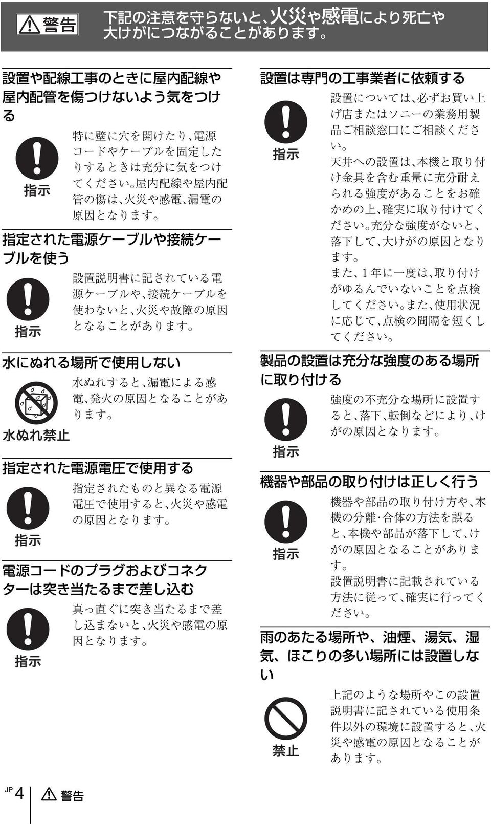
35 Owner s Record The model and serial numbers are located on the bottom. Record these numbers in the spaces provided below. Refer to these numbers whenever you call upon your Sony dealer regarding this product. Model No. Serial No. WARNING To reduce a risk of fire or electric shock, do not expose this product to rain or moisture. To avoid electrical shock, do not open the cabinet. Refer servicing to qualified personnel only. WARNING This installation should be made by a qualified service person and should conform to all local codes. WARNING A readily accessible disconnect device shall be incorporated in the building installtion wiring. WARNING (for Installers only) Instructions for installing the equipment on the ceiling: After the installtion, ensure the connection is capable of supporting four times the weight of the equipment downwards. CAUTION The rating label is located on the bottom. CAUTION for LAN port For safety reason, do not connect the LAN port to any network devices that might have excessive voltage. Power Supply Caution for U.S.A. and Canada The SNC-RZ25N operates on 24V AC or 12V DC. The SNC-RZ25N automatically detects the power. Use a Class 2 power supply which is UL Listed (in the U.S.A) or CSA-certified (in Canada) Caution for other countries The SNC-RZ25P operates on 24V AC or 12V DC. The SNC-RZ25P automatically detects the power. Use a power supply rated 24 V AC or 12 V DC which meets the requirements for SELV (Safety Extra Low Voltage) and complies with Limited Power Source according to IEC For customers in the U.S.A. (SNC- RZ25N only) This device complies with Part 15 of the FCC Rules. Operation is subject to the following two conditions: (1) This device may not cause harmful interference, and (2) this device must accept any interference received, including interference that may cause undesired operation. NOTE: This equipment has been tested and found to comply with the limits for a Class A digital device, pursuant to part 15 of the FCC Rules. These limits are designed to provide reasonable protection against harmful interference when the equipment is operated in a commercial environment. This equipment generates, uses, and can radiate radio frequency energy and, if not installed and used in accordance with the instruction manual, may cause harmful interference to radio communications. Operation of this equipment in a residential area is likely to cause harmful interference in which case the user will be required to correct the interference at his own expense. You are cautioned that any changes or modifications not expressly approved in this manual could void your authority to operate this equipment. The shielded interface cable recommended in this manual must be used with this equipment in order to comply with the limits for a digital device pursuant to Subpart B of Part 15 of FCC Rules. GB 1 GB
36 For customers in Canada (SNC- RZ25N only) This Class A digital apparatus complies with Canadian ICES-003. Pour les utillisateurs au Canada (SNC-RZ25N seulement) Cet appareil numérique de la classe A est conforme à la norme NMB-003 du Canada. For customers in other countries WARNING This is a Class A product. In a domestic environment, this product may cause radio interference in which case the user may be required to take adequate measures. In the case that interference should occur, consult your nearest authorized Sony service facility. ATTENTION The electromagnetic fields at specific frequencies may influence the picture of the unit. GB 2
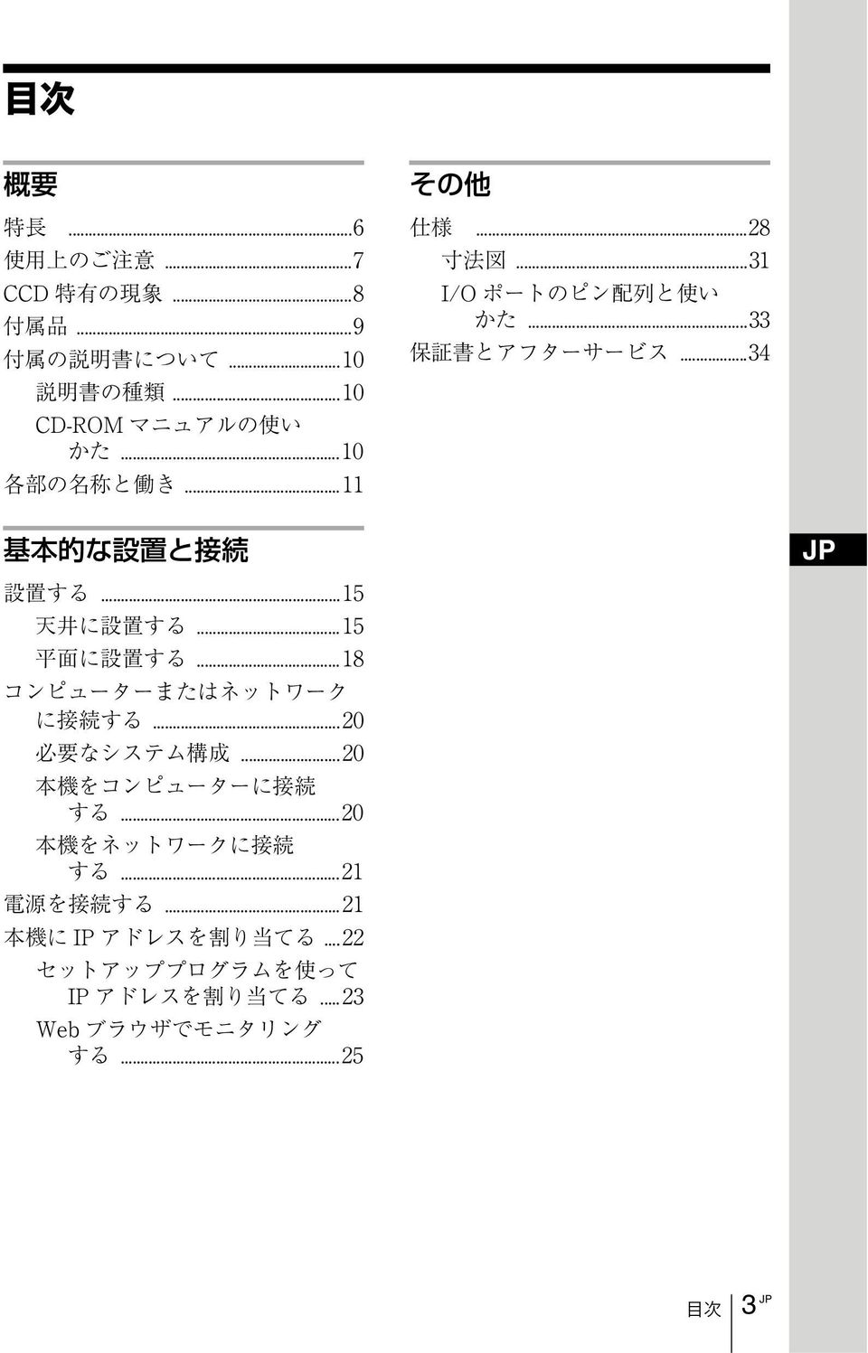
37 Table of Contents Overview Features...4 Precautions...5 Operating Precautions...5 Typical CCD Phenomena...7 Supplied Accessories...7 About the Supplied Manuals...8 Names of Manuals...8 Using the CD-ROM Manuals...8 Location and Functions of Parts and Controls...9 Others Specifications Dimensions Pin Assignment and Use of I/O Port Basic Installation and Connections Installing the Camera...12 Installing the Camera on the Ceiling...12 Installing the Camera on a Flat Surface...15 Connecting to a Computer or a Network...17 System Requirements...17 Connecting the Camera to a Local Network...18 Connecting the Camera to a Computer...18 Connecting Power...19 Assigning the IP Address to the Camera...20 Assigning the IP Address Using the Setup Program...20 Accessing the Camera Using the Web Browser...22 Table of Contents 3 GB
38 B Overview Features High-quality monitoring via the network You can monitor a high-quality live image from the camera using the Web browser on the computer connected to the 10BASE-T or 100BASE-TX network. The maximum frame rate is 30 FPS for the SNC-RZ25N and 25 FPS for the SNC-RZ25P. Up to 20 users can view the image from one camera at the same time (in JPEG mode). Available Web browsers Microsoft Internet Explorer Ver. 5.5 or 6.0 Available OS: Windows 2000/ XP Remote-controllable high-speed pan/tilt mechanism and high magnification auto-focus zoom lens The camera is provided with a high-speed (100 rotation / second), wide-angle ( 170 to +170 ) pan mechanism, a high-speed (90 rotation / second), wide-angle ( 90 to +30 ) tilt mechanism, and a high-magnification zoom lens with optical zoom of 18 magnifications, electrical zoom of 12 magnifications, giving 216 magnifications in total. and after the trigger to an FTP server, or send them periodically. Preset positions and Tour programs You can save up to 16 preset positions (pan, tilt and zoom positions) of the camera, and up to 5 tour programs composed from the preset positions. You can activate the preset positions by synchronizing with the external sensor input or built-in activity detection function. Alarm output The camera is equipped with two sets of alarm outputs. You can use them to control peripheral devices by synchronizing with the external sensor inputs, built-in activity detection function, manual trigger button, Day/Night function or timer. Direct panning/tilting Clicking on the desired point in the displayed window allows you to pan and tilt the camera in the direction of that point. Wireless LAN Inserting the wireless card SNCA-CFW1 (option) especially designed to use with this camera into the CF card slot enables transmission of images from the camera via wireless LAN. Image transmission using an E- mail or FTP server You can send a still image from the camera as an attachment of an or to an FTP server, at the moment when a trigger by the external sensor input, built-in activity detection function or manual trigger button occurs. You can also send still images sequentially for a determined period before GB 4 Features
39 Precautions This Sony product has been designed with safety in mind. However, if not used properly electrical products can cause fires which may lead to serious body injury. To avoid such accidents, be sure to heed the following. Heed the safety precautions Be sure to follow the general safety precautions, and the Operating Precautions. In case of a breakdown In case of a system breakdown, discontinue use and contact your authorized Sony dealer. In case of abnormal operation If the unit emits smoke or an unusual smell, If water or other foreign objects enter the cabinet, or If you drop the unit or damage the cabinet: 1 Disconnect the camera cable and the connecting cables. 2 Contact your authorized Sony dealer or the store where you purchased the product. Operating Precautions Operating or storage location Avoid operating or storing the camera in the following locations: Extremely hot or cold places (Operating temperature: 0 C to +40 C [32 F to 104 F]) Exposed to direct sunlight for a long time, or close to heating equipment (e.g., near heaters) Close to sources of strong magnetism Close to sources of powerful electromagnetic radiation, such as radios or TV transmitters Locations subject to strong vibration or shock Ventilation To prevent heat buildup, do not block air circulation around the camera. Transportation When transporting the camera, repack it as originally packed at the factory or in materials of equal quality. Cleaning Use a blower to remove dust from the lens or optical filter. Use a soft, dry cloth to clean the external surfaces of the camera. Stubborn stains can be removed using a soft cloth dampened with a small quantity of detergent solution, then wipe dry. Do not use volatile solvents such as alcohol, benzene or thinners as they may damage the surface finishes. Overview Note on laser beams Laser beams may damage the CCDs. If you shoot a scene that includes a laser beam, be careful not to let a laser beam become directed into the CCDs of the camera. Precautions 5 GB
40 The Network Camera system and related service is not a security service. When monitoring the image and audio of the purchased Network Camera, there is a risk that the monitoring image or audio may be viewed or used by a thirdparty via the network. It is provided only as a convenience for people to easily access their cameras via the internet. When you use the Network Camera, please take into account and ensure the privacy and portrait right of the object at your own responsibility. Access to the camera or system is limited to the user setting up a user name and password only. No further authentication is provided nor should the user presume that such filtering is done by the service. Sony assumes no liability should the service related to the Network Camera goes down or interrupted for whatever reason. NOTICE TO USERS 2005 Sony Corporation. All rights reserved. This manual or the software described herein, in whole or in part, may not be reproduced, translated or reduced to any machine readable form without prior written approval from Sony Corporation. SONY CORPORATION PROVIDES NO WARRANTY WITH REGARD TO THIS MANUAL, THE SOFTWARE OR OTHER INFORMATION CONTAINED HEREIN AND HEREBY EXPRESSLY DISCLAIMS ANY IMPLIED WARRANTIES OF MERCHANTABILITY OR FITNESS FOR ANY PARTICULAR PURPOSE WITH REGARD TO THIS MANUAL, THE SOFTWARE OR SUCH OTHER INFORMATION. IN NO EVENT SHALL SONY CORPORATION BE LIABLE FOR ANY INCIDENTAL, CONSEQUENTIAL OR SPECIAL DAMAGES, WHETHER BASED ON TORT, CONTRACT, OR OTHERWISE, ARISING OUT OF OR IN CONNECTION WITH THIS MANUAL, THE SOFTWARE OR OTHER INFORMATION CONTAINED HEREIN OR THE USE THEREOF. Sony Corporation reserves the right to make any modification to this manual or the information contained herein at any time without notice. The software described herein may also be governed by the terms of a separate user license agreement. IPELA and are trademarks of Sony Corporation. Microsoft, Windows, Internet Explorer and MS-DOS are registered trademarks of Microsoft Corporation in the United States and/or other countries. Java is a trademark of Sun Microsystems, Inc. in the United States and other countries. Intel and Pentium are registered trademarks of Intel Corporation or its subsidiaries in the United States andother countries. Adobe, Acrobat and Adobe Reader are trademarks of Adobe Systems Incorporated in the United States and/or other countries. All other company and product names are trademarks orregistered trademarks of the respective companies ortheir respective makers. GB 6 Precautions
41 Typical CCD Phenomena Supplied Accessories The following phenomena may appear on the monitor screen while you are using a CCD * color video camera. These phenomena stem from the high sensitivity of the CCD image sensors, and do not indicate a fault within the camera. When you unpack, check that all the supplied accessories are included. Camera (1) Overview Vertical smear A smear may appear to extend vertically from very bright subjects, as shown below. Video monitor screen Pale vertical smear Very bright subject (such as an electric lamp, fluorescent lamp, sunlight, or strong reflected light) This phenomenon is common to CCD imaging elements using an interline transfer system, and is caused when electric charge induced by infrared radiation deep within the photo sensor is transferred to the resistors. CD-ROM (including the Setup Program and User s Guide) (1) Ceiling bracket (A) (1) Aliasing When shooting fine stripes, straight lines or similar patterns, the lines may become slightly jagged. Blemishes A CCD image sensor consists of an array of individual picture elements (pixels). A malfunctioning sensor element will show up as a single pixel blemish in the image. This is generally not a problem. Ceiling bracket (B) (1) White speckles When you shoot a poorly illuminated object at a high temperature, small white dots may appear all over the entire screen image. * CCD: Charge-Coupled Device Typical CCD Phenomena / Supplied Accessories 7 GB
42 Wire rope (1) About the Supplied Manuals Screws 3M3 6 (6) Installation Manual (this document) (1) B&P Warranty Booklet (1) (SNC-RZ25N only) Names of Manuals The following manuals are supplied with this unit. Installation Manual (this document) The Installation Manual describes the names and functions of the parts of the camera, the installation and connections of the camera, etc. Be sure to read it before operating the camera. User s Guide (stored in the CD- ROM) The User s Guide describes the setup of the camera and the operations from the Web browser. To open the User s Guide, see Using the CD-ROM Manuals below. Using the CD-ROM Manuals The supplied CD-ROM disc includes the User s Guides for the SNC-RZ25N/RZ25P (Japanese, English, French, German, Spanish, Italian and Chinese versions). CD-ROM System Requirements The following are required to access the supplied CD-ROM disc. Computer: PC with Intel Pentium CPU Installed memory: 64 MB or more CD-ROM drive: 8 or faster Monitor: Monitor supporting resolution of or higher OS: Microsoft Windows Millennium Edition, Windows 2000 Service Pack 2, Windows XP Professional or Home Edition When these requirements are not met, access to the CD-ROM disc may be slow, or not possible at all. GB 8 About the Supplied Manuals
43 Preparations The Adobe Acrobat Reader Version 4.0 or later or the Adobe Reader Version 6.0 or later must be installed on your computer in order to use the User s Guide contained in the CD-ROM disc. Note If Adobe Acrobat Reader or Adobe Reader is not installed, it may be downloaded from the following URL: readstep2.html Location and Functions of Parts and Controls Front Overview Reading the manual in the CD-ROM 1 Insert the supplied CD-ROM into the CD-ROM drive. After a short time a window will open displaying the files on the CD-ROM. 2 Double-click the PDF file of the SNC- RZ25N or SNC-RZ25P named English. The application will start, then the cover page of the User s Guide of the SNC- RZ25N or SNC-RZ25P is displayed. Clicking an item in the Table of Contents allows you jump to the relevant page. Note If you lose the CD-ROM disc or become unable to read its content, for example because of a hardware failure, contact a Sony service representative. 5 1 NETWORK indicator (orange/ green) The indicator flashes in orange when the camera is connected to the 10BASE-T network; it flashes in green when the camera is connected to the 100BASE- TX network. The indicator goes off when the camera is not connected to the network. 2 CF card slot Insert the wireless LAN card SNCA- CFW1 especially designed to use with this camera or the storage (not supplied) into the slot. And the SNCA-CFW1 can be attached with the optional antenna SNCA-AN1. It can expand the transmission area with the wireless LAN. Note Insert the CF card with its front side towards the NETWORK and POWER indicators. Location and Functions of Parts and Controls 9 GB
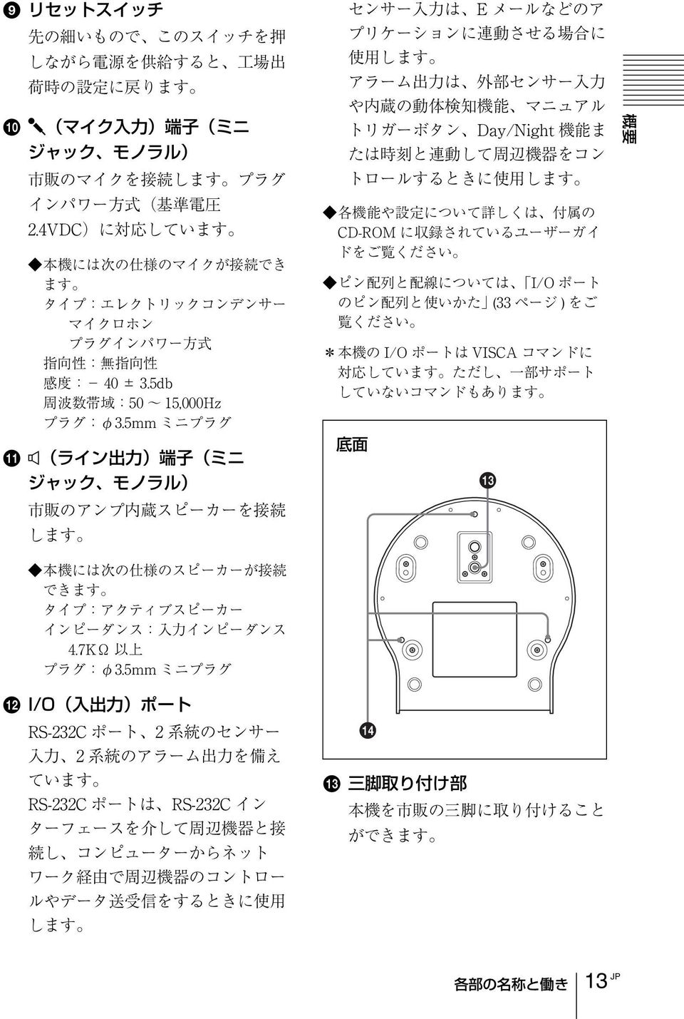
44 3 CF card lever Press the lever to remove the CF card from the CF card slot. 4 POWER indicator (green) When the power is supplied to the camera, the camera starts checking the system. If the system is normal, this indicator lights up. If a system error occurs, this indicator flashes every second. In this case, consult your authorized Sony dealer. 5 Lens A 18 optical zoom, auto-focus lens is mounted as standard equipment. Rear IMAGE FLIP DC 12V + 1 AC 24V 2 m T (video output) connector (BNC type) Outputs a composite video signal. Connect to a composite video input connector of a video monitor, VCR, etc. 9 Reset switch To reset the camera to the factory default settings, supply the power to the camera, while holding down this switch with a pointed object. q; m (microphone input) jack (minijack, monaural) Connect a commercially available microphone. This jack supports plug-inpower microphones (rated voltage: 2.4 V DC). You can connect the microphones of the following specifications to this camera. Type: Electric condenser microphone Plug-in power system Directivity: Nondirectional Sensitivity: 40 ± 3.5 db Frequency range: 50 15,000 Hz qa 5 (line output) jack (minijack, monaural) Connect a commercially available speaker system with the built-in amplifier. You can connect the speakers of the following specifications to this camera. Type: Active speaker Impedance: Input impedance 4.7 kohms or more Plug: ø3.5 Mini-plug 9 0 qa qs 6 (network) port (RJ45) Connect to the 10BASE-T or 100BASE- TX network using a network cable (UTP, category 5). 7 DC 12 V/AC 24 V (power input) terminal Connect to a 12V DC or 24V AC power supply system. qs I/O (Input/Output) port This port is provided with an RS-232C port, two sensor inputs and two alarm outputs. The RS-232C port is used when you connect peripheral devices to the camera using the RS-232C interface, and control the devices from the computer or transmit/receive data from the devices via the network. The sensor input is used as the alarm input. The camera operation can be synchronized with or other applications. GB 10 Location and Functions of Parts and Controls
45 The alarm output is used to control connected peripheral devices by synchronizing with an external sensor input, the built-in activity detection function, a manual trigger button, Day/ Night function or the timer function. For details on each function and required settings, see the User s Guide stored in the supplied CD-ROM. For pin assignment and wiring, see Pin Assignment and Use of I/O Port on page 28. The I/O Port of this unit corresponds to the VISCA command. However, there are some commands which are not supported. Overview Bottom qd qf qd Tripod mounting hole Use this hole to attach a commercially available tripod when attaching the camera to the tripod. qf Ceiling bracket mounting screw holes When installing the camera to the ceiling, secure the supplied ceiling brackets to these holes using the supplied screws. Location and Functions of Parts and Controls 11 GB
46 B Basic Installation and Connections Installing the Camera Installing the Camera on the Ceiling Using the supplied ceiling brackets, wire rope and screws, you can utilize existing junction boxes, etc., to attach the camera to the ceiling. When you install the camera, always install it on a level ceiling. If you have to install it on a sloping or uneven ceiling, make sure that the place where you install it is within ±15 degrees of the horizontal in order to ensure the pan/tilt mechanism functions properly. Notes If you attach the camera to the ceiling, entrust the installation to an experienced contractor or installer. If you install the camera on the ceiling, ensure that the ceiling is strong enough to withstand the weight of the camera plus the ceiling brackets and then install the camera securely. If the ceiling is not strong enough, the camera may fall and cause serious injury. To prevent the camera from falling, make sure to attach the supplied wire rope. If you attach the camera to the ceiling, check periodically, at least once a year, to ensure that the connection has not loosened. If conditions warrant, make this periodic check more frequently. Installation 1 Attach the wire rope to the junction box in the ceiling. Use a screw hole and a screw (not supplied) in the junction box to attach the wirerope. Ceiling Hole for connecting cable Before installation After deciding the direction in which the camera will shoot, make the required holes for the junction box, and connecting cables. Note The connecting cables cannot be passed through the ceiling bracket (A). A hole for the wiring is required in the ceiling at the back of the camera where it is attached to the ceiling. GB 12 Installing the Camera
47 2 Attach the ceiling bracket (B) to the junction box on the ceiling. Align the holes in the bracket with those in the junction box, and use appropriate screws (not supplied). There are elongated holes for the screws along the rounded edges of the ceiling bracket (B). Later, the front of the camera will be positioned along this edge. Face the camera to the front, adjust the aim, and attach it securely. 3 Attach the ceiling bracket (A) to the bottom of the camera using the supplied three screws (3M 3 6) supplied. Align the screw holes on the bottom of the camera with those in the ceiling bracket, and attach the bracket to the camera. Attach the wire rope at the same time. Ceiling 3M 3 6 (supplied) Ceiling Basic Installation and Connections Ceiling bracket (A) Ceiling bracket (B) Front of the camera Tighten the screws a bit at a time in the numbered order shown in the illustration. Attach the wire rope using the screw designated as number 3 above. After all of Installing the Camera 13 GB
48 the screws are temporarily tightened properly, securely tighten each one in turn. Note For assembly, use only the screws supplied with the camera. Using other screws may damage the camera. 5 While pushing up on the front part of the camera, attach it using the supplied three screws (3M 3 6), starting with the screw at position 1. Ceiling 4 Insert the protrusions raised on the ceiling bracket (A) into the spaces prepared in the ceiling bracket (B), and temporarily attach them by pushing the ceiling bracket (A) to the rear Ceiling bracket (B) Ceiling 3M 3 6 (supplied) 6 Connect the cables to the connectors on the rear of the camera. Ceiling bracket (A) Ceiling Note Take the proper steps to ensure that the load of the cables connected does not cause problems. GB 14 Installing the Camera
49 Removing the camera 1 Remove the three screws used to attach the camera in step 5 of Installation. 2 While pushing the entire camera up towards the ceiling, move the camera to the front. The hooks will disengage, and you can remove the camera. Installing the Camera on a Flat Surface Be sure to place the camera on a flat surface. If you must place the camera on an inclined surface, place it within ±15 degrees of the horizontal in order to ensure the pan/tilt mechanism functions properly, and take countermeasure for preventing the camera from falling. Notes Do not grasp the camera head when carrying the camera. Do not turn the camera head manually. Doing so will result in the camera malfunctioning. Basic Installation and Connections Installing the Camera 15 GB
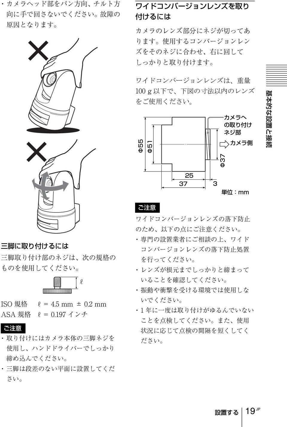
50 To attach the camera to a tripod Use a tripod with screws meeting either of the following specifications. length ISO standard: length 4.5 mm ±0.2 mm ASA standard: length inches To attach a wide conversion lens The camera s lens portion is threaded. To attach the conversion lens you use, align the lens with those threads, and turn it to the right to attach it securely. Acceptable wide conversion lenses should weigh less than 100 g (4 oz), and should not exceed the dimensions given in the illustration below. Notes To attach a tripod, use the tripod mounting screw hole and attach the tripod firmly with a screwdriver. Install the tripod on a flat surface. 55 (2 5 / 32 ) 51 (2) Screw tapping used to attach the camera Camera side 25 ( 31 / 32 ) 37 (1 15 / 32 ) 37 (1 15 / 32 ) 3 ( 1 / 8 ) Unit: mm (inch) Notes In order to prevent the wide conversion lens from falling, follow the advice given below. Consult with an experienced contractor or installer to take countermeasure to ensure the wide conversion lens does not come loose and fall. Be sure that the lens is tightened securely, as far as it will go. Do not use a wide conversion lens in an environment where it is subject to vibration or shock. Check periodically, at least once a year, to ensure that the connection has not loosened. If conditions warrant, make this periodic check more frequently. GB 16 Installing the Camera
51 Connecting to a Computer or a Network To connect to the computer, use a commercially available network cable (cross cable). To connect to the network, use a commercially available network cable (straight cable). System Requirements Processor Pentium III 1 GHz or higher (Pentium 4, 2 GHz or higher recommended) RAM 256 MB or more OS Windows 2000/ XP Web browser Internet Explorer Ver. 5.5 or Ver. 6.0 Basic Installation and Connections Connecting to a Computer or a Network 17 GB
52 Connecting the Camera to a Computer Using a commercially available network cable (cross), connect the (network) port on the camera on the network connector of a computer. SNC-RZ25N/RZ25P (rear) DC 12V 1 AC 24V 2 + Connecting the Camera to a Local Network Using a commercially available network cable, connect the (network) port on the camera to a hub in the network. SNC-RZ25N/RZ25P (rear) DC 12V 1 AC 24V + 2 m IMAGE FLIP m Network cable (cross, not supplied) Network cable (straight, not supplied) Network connector 10BASE-T/ 100BASE-TX Hub Network Computer GB 18 Connecting to a Computer or a Network
53 Connecting Power Two power supply systems are provided for the camera. 12 V DC 24 V AC Connect the 12 V DC or 24 V AC power supply system to the power input terminal on the rear of the Camera. m 5 DC 12V 1 AC 24V to 12 V DC or 24 V AC About the power source Use the 12 V DC or 24 V AC power source isolated from the 100 to 240 V AC. The usable voltage range is as follows: 12 V DC: 10.8 to 13.2 V 24 V AC: 21.6 to 26.4 V Recommended power cable 12 V DC Cable (AWG) Maximum cable length (m (feet)) 24 V AC Cable (AWG) Maximum cable length (m (feet)) #24 (0.22 mm) 4.5 (14.8) #24 (0.22 mm) 10.5 (34) #22 (0.33 mm) 7.5 (24.6) #22 (0.33 mm) 16.5 (54) #20 (0.52 mm) 12 (39) #20 (0.52 mm) 27.5 (90) #18 (0.83 mm) 21 (69) #18 (0.83 mm) 45.5 (149) Basic Installation and Connections Use the UL cable (VW-1 style 1007) for 12 V DC or 24 V AC connection. Connecting Power 19 GB
54 Assigning the IP Address to the Camera To connect the camera to a network, you need to assign a new IP address to the camera. Before assigning the IP address, connect the camera to a computer or a network. For details, see Connecting to a Computer or a Network (page 17). You can assign the IP address in two ways: Using the setup program stored in the supplied CD-ROM For details on the operations, see Assigning the IP Address Using the Setup Program on page 20. Using the ARP (Address Resolution Protocol) commands Open the DOS window on the computer and enter the specified ARP commands. For details on the operations, see Assigning the IP Address to the Camera Using ARP Commands in the User s Guide stored in the supplied CD-ROM. Note For determining the IP address to be assigned to the camera, consult your system administrator. Assigning the IP Address Using the Setup Program 1 Insert the supplied CD-ROM disc into your CD-ROM drive. After s short time a window will open displaying the files on the CD-ROM. 2 Click the Setup icon of IP Setup Program. The File Download dialog opens. 3 Click Open. Note You cannot install the IP Setup Program properly if you click Save in the File Download dialog. 4 Install the IP Setup Program to your computer following the wizard displayed. If Software License Agreement is displayed, read it carefully and accept the agreement to continue the installation. 5 Start the IP Setup Program. The program detects the SNC-RZ25N or SNC-RZ25P connected on the local GB 20 Assigning the IP Address to the Camera
55 network and lists it (them) on the Network tab window. and Default gateway in the relevant boxes. 8 Set the DNS server address. 6 Click the camera you want to assign a new IP address in the list. To obtain the DNS server addresses automatically: Select Obtain DNS server address automatically. To specify the DNS server addresses manually: Select Use the following DNS server address, and type the Primary DNS server address and Secondary DNS address in the relevant boxes. Basic Installation and Connections The network settings for the selected camera are displayed. 7 Set the IP address. To obtain the IP address automatically from a DHCP server: Select Obtain an IP address automatically. The IP address, Subnet mask and Default gateway are assigned automatically. To specify the IP address manually: Select Use the following IP address, and type the IP address, Subnet mask Note The Third DNS server address and Fourth DNS server address are invalid for this camera. 9 Set the HTTP port number. Normally select 80 for the HTTP port No. To use another port number, select the text box and type a port number between 1024 and Type the Administrator name and Administrator password. Assigning the IP Address to the Camera 21 GB
56 The default settings of both items are admin. Note You cannot change the Administrator name and Administrator password in this step. To change these items, see Setting the User User setting Page of the User s Guide stored in the supplied CD-ROM. 11Confirm that all items are correctly set, then click OK. If Setting OK is displayed, the IP address is correctly assigned. 12To access the camera directly, double-click the camera name in the list. Accessing the Camera Using the Web Browser When the IP address has been assigned to the camera, check that you can actually access the camera using the Web browser installed in your computer. This section explains how to access the camera using the Internet Explorer. For details on the operations using the Web browser, i.e. for using a Web browser that is not the Internet Explorer, see the User s Guide stored in the supplied CD-ROM. 1 Start the Web browser on the computer and type the IP address of this camera in the URL box. Example: The Welcome page is displayed. The welcome page of the network camera SNC-RZ25N or SNC-RZ25P is displayed. 2 Click Enter. The main viewer is displayed. Note If the IP address is not set correctly, the welcome page does not appear after step 12. In this case, try to set the IP address again. GB 22 Assigning the IP Address to the Camera
57 Tip Every page of this software is optimized as display character size Medium for Internet Explorer. To display the Welcome page correctly To operate the welcome page correctly, set the security level of the Internet Explorer to Medium or lower, as follows: When the main viewer is correctly displayed, the IP address assignment is completed. When the main viewer of the camera is displayed for the first time When you click Enter, Security warning is displayed. When you click OK, the ActiveX control is installed and the main viewer is displayed. 1 Select Tool from the menu bar for Internet Explorer, then select Internet Options and Security tab in sequence. 2 Click the Internet icon (when using the camera via the Internet) or Local intranet icon (when using the camera via a local network). 3 Set the slider to Medium or lower. (If the slider is not displayed, click Default Level.) Basic Installation and Connections Notes If Automatic configuration is enabled in the Local Area Network (LAN) Settings on Internet Explorer, the image may not be displayed. In this case, disable Automatic configuration and set the Proxy server manually. For setting the Proxy server, consult your network administrator. When you install ActiveX viewer on Windows 2000 or Windows XP, you should have logged in the computer as the Administrator. When using antivirus software in the computer When you use antivirus software in your computer, the camera performance may be reduced, for example, the frame rate for displaying the image may be lower. The Web page displayed when you log in the camera uses Java Script. The display of the Web page may be affected if you use antivirus software in your computer. Assigning the IP Address to the Camera 23 GB
58 B Others Specifications Network Protocol TCP/IP, ARP, ICMP, HTTP, FTP (server/client), SMTP (client), DHCP (client), DNS (client), NTP (client), SNMP (MIB-2), RTP/RTCP, PPPoE Compression Video compression format MPEG4/JPEG (selectable) Audio compression format G.711/G726 (40,32,24,16 kbps) Image size (VGA), , , (QVGA), , (QQVGA) Maximum frame rate SNC-RZ25N Max. 30 FPS (QVGA) SNC-RZ25P Max. 25 FPS (QVGA) Web browser Internet Explorer Ver. 5.5 or 6.0 (Available OS: Windows 2000/ XP) Computer environments CPU: Pentium III, 1 GHz or higher (Pentium 4, 2 GHz or higher recommended) RAM: 256 MB or more Display size: Maximum user access In JPEG mode: 20 users In MPEG4 mode: 10 users Network security Password (basic authentication), IP filtering Homepage customization Starting from a homepage in the built-in flash memory or CF is possible. Other functions Activity detection, image trimming, built-in clock, etc. Camera Video signal SNC-RZ25N: NTSC Color SNC-RZ25P: PAL Color Picture element 1/4 inch color CCD (Total picture elements: SNC-RZ25N: Approx. 410,000 SNC-RZ25P: Approx. 470,000) (Effective picture elements: SNC-RZ25N: Approx. 380,000 SNC-RZ25P: Approx. 440,000) Lens 18 (Optical), 12 (Digital) f=4.1 to 73.8 mm, F1.4 to F3.0 Horizontal angle: 2.7 to 48.0 Minimum object distance 30 mm (1 3 /16 inch): Minimum illumination 0.7 lx (F1.4)/with 50 IRE Shutter speed 1/1 to 1/10,000 s Horizontal resolution NTSC : 470 TV (WIDE end) PAL : 460 TV (WIDE end) Video S/N 50 db Mechanism Pan 170º to +170º, Maximum speed: 100 / s Tilt 90º to +30º, Maximum speed: 90 / s Interface Network port 10BASE-T/100BASE-TX (RJ-45) I/O port Sensor input : 2, make contact Alarm output : 2, 24 V AC/DC, 1 A (mechanical relay outputs electrically isolated from the camera) Serial interface Transparency type RS-232C Video output VIDEO OUT: BNC, 1.0 Vp-p, 75 ohms, unbalanced, sync negative CF card slot Wirless card (802.11b) Memory card (storage) Microphone input Sensitivity: 40 ± 3.5 db Freguency range: 50-15,000Hz plug: ø3.5 mm ( 5 /32 inches), Miniplug, plug-in power system GB 24 Specifications
59 Line output Type: Active speaker Input impedance: 4.7 kohms or more plug: ø3.5 mm ( 5 /32 inches), Miniplug Others Power supply 12 V DC ± 10% 24 V AC ± 10%, 50/60 Hz Power consumption 17 W max. Operating temperature 0 C to 40 C (32 F to 104 F) Storage temperature 20 C to +60 C ( 4 F to +140 F) Operating humidity 20 to 80 % Storage humidity 20 to 95 % Dimensions mm (7 7 /8 5 5 /8 5 7 /8 inches) not including the projecting parts, lens and tripod adapter Mass Approx. 1.3 kg (2 lb 14 oz) Supplied accessories CD-ROM (setup program and User s Guide) (1) Ceiling bracket (A) (1) Ceiling bracket (B) (1) Wire rope (1) Screws 3M 3 6 (6) Installation Manual (this document) (1) B&P Warranty Booklet (1) (SNC- RZ25N only) Regular parts replacement Some of the parts that make up this product (electrolytic condenser, for example) need replacing regularly depending on their life expectancies. The lives of parts differ according to the environment or condition in which this product is used and the length of time it is used, so we recommend regular checks. Consult the dealer from whom you bought it for details. Others Optional accessories Wirless card SNCA-CFW1 Antenna for wireless card SNCA-AN1 Memory stick Duo adapter corresponding to compact flash slot MSAC-MCF1 Memory stick Duo MSX-M512S (512MB) Design and specifications are subject to change without notice. Specifications 25 GB
60 Dimensions Front Top 147 (5 7 /8) 206 (8 1 /8) (5 5 / 8 ) Side Bottom 90 ø5, Depth 5 ( 7 /32) ( 9 /16) 20 ( 13 /16) Tripod screw hole 1 /4-20UNC, Depth 6.5 ( 9 /32) 70 (2 7 / 8 ) 148 (5 7 / 8 ) 12 ( 1 / 2 ) Unit: mm (inches) GB 26 Specifications
61 Dimensions with ceiling brackets Front Side 141 (5 5 / 8 ) 140 (5 5 / 8 ) 71 (2 7 / 8 ) 89 (3 5 / 8 ) Others (1 13 /16) 216 (8 5 /8) Ceiling bracket (B) Adjustable range: ± 30º Rear Attachment hole ø 88.9 (3 1 /2) (Width 4.5 ( 3 /16)) ( 2) Attachment hole ø (4 1 /4) (Width 4.5 ( 3 /16)) ( 2) Attachment hole ø 4.5 ( 3 /16) ( 4) 45 Front 83.5 (3 3 / 8 ) Attachment hole ø 83.5 (3 3 /8) (Width 4.5 ( 3 /16)) ( 2) Attachment hole ø (4 7 /8) (Width 4.5 ( 3 /16)) ( 4) Unit: mm (inches) Specifications 27 GB
62 I/O Pin Assignment and Use of I/O Port Pin assignment of I/O port Using the I/O receptacle While holding down the button on the slot to which you want to connect the wire (AWG No. 28 to 22) with a small slotted screwdriver, insert the wire into the slot. Then release the screwdriver from the button. 1 Pin No. Pin name Wire 1 Sensor In Sensor In 1 (GND) 3 Sensor In Sensor In 2 (GND) 5 Alarm Out Alarm Out 1 7 Alarm Out Alarm Out 2 9 GND 10 GND 11 RS232C RX 12 RS232C TX 2 Slotted screwdriver I/O Repeat this procedure to connect all required wires. GB 28 Specifications
63 Wiring diagram for sensor input Mechanical switch/open collector output device Camera Inside Outside 5 V 2.35 kohms 1 pin (Sensor In ) 2 or 4 pin (GND) GND Mechanical switch or Open collector output device Others Wiring diagram for alarm output Camera Inside Outside 5 or 7 pin (Alarm output +) 5 V Magnet relay 24 V AC/24 V DC, 1 A or less 6 or 8 pin (Alarm output ) Circuit example R GND Specifications 29 GB
64
65 AVERTISSEMENT Afin de réduire les risques d incendie ou d électrocution, ne pas exposer cet appareil à la pluie ou à l humidité. Afin d écarter tout risque d électrocution, garder le coffret fermé. Ne confier l entretien du produit qu à un personnel qualifié. AVERTISSEMENT L installation doit être effectuée par un technicien qualifié et se conformer à toute la réglementation locale. AVERTISSEMENT Un dispositif coupe-circuit facilement accessible doit être incorporé au câblage de l installation du bâtiment. AVERTISSEMENT (pour les installateurs seulement) Instructions pour l installation du matériel au plafond : Après l installation, assurez-vous que le montage est suffisamment solide pour supporter quatre fois le poids du matériel vers le bas. PRECAUTION La plaquette des caractéristiques nominales se trouve sur la face inférieure. PRECAUTION pour le port réseau local Pour la sécurité, ne connectez pas le port réseau local à un périphérique réseau susceptible de présenter une tension excessive. Alimentation Avertissement pour les États-Unis et le Canada La SNC-RZ25N fonctionne sur du 24 V CA ou 12 V CC. La SNC-RZ25N détecte automatiquement l alimentation. Utilisez une alimentation classe 2 répertoriée UL (aux États-Unis) ou homologuée CSA (au Canada). Avertissement pour les autres pays La SNC-RZ25P fonctionne sur du 24 V CA ou 12 V CC. La SNC-RZ25P détecte automatiquement l alimentation. Utilisez une alimentation nominale de 24 V CA ou 12 V CC répondant aux prescriptions pour une SELV (Safety Extra Low Voltage - tension de sécurité extra-réduite) et conforme à une source d alimentation limitée selon la norme IEC Veuillez noter que tout changement ou toute modification de ce matériel non expressément autorisés dans ce manuel peuvent entraîner la révocation de votre droit de l utiliser. Pour les utilisateurs au Canada (SNC- RZ25N seulement) Cet appareil numérique de la classe A est conforme à la norme NMB-003 du Canada. Pour les utilisateurs dans d autres pays AVERTISSEMENT Il s agit d un produit de Classe A. Dans un environnement familial, ce produit peut causer une interférence radio, auquel cas l utilisateur devra prendre des mesures adéquates. En cas d interférence, consultez votre revendeur Sony agréé le plus proche. ATTENTION Des champs électromagnétiques à des fréquences spécifiques peuvent avoir une incidence sur l image de cet appareil. FR 1 FR
66 Table des matières Description générale Caractéristiques...3 Précautions...4 Précautions d utilisation...4 Phénomènes caractéristiques du CCD...6 Accessoires fournis...7 Notes sur les manuels fournis...8 Noms des manuels...8 Utilisation des manuels sur le CD-ROM...8 Emplacement et fonctions des pièces et commandes...9 Autres informations Spécifications Dimensions Brochage et utilisation du port I/O (E/S) Installation et raccordements de base Installation de la caméra...12 Installation de la caméra au plafond...12 Installation de la caméra sur une surface horizontale...15 Raccordement à un ordinateur ou à un réseau...17 Configuration système requise...17 Raccordement de la caméra à un ordinateur...18 Raccordement de la caméra à un réseau local...18 Alimentation à raccorder...19 Attribution d une adresse IP à la caméra...20 Attribution de l adresse IP à l aide du programme d installation...20 Accès à la caméra à l aide du navigateur Internet FR Table des matières
67 B Description générale Caractéristiques Visualisation d image de haute qualité via un réseau Vous pouvez visualiser en direct une image de haute qualité de la caméra en utilisant le navigateur Internet d un ordinateur connecté à un réseau 10BASE-T ou 100BASE-TX. Le taux de trame maximum est de 30 FPS pour la SNC-RZ25N et de 25 FPS pour la SNC-RZ25P. Jusqu à 20 utilisateurs peuvent visualiser simultanément l image d une même caméra (en mode JPEG). Navigateur Internet disponible Microsoft Internet Explorer Ver. 5.5 ou 6.0 Système d exploitation disponible : Windows 2000/ XP Dispositif de panoramique/ inclinaison rapide télécommandable et objectif zoom autofocus à fort grossissement La caméra est dotée d un dispositif de panoramique grand-angle ( 170 à +170 ) à grande vitesse (rotation de 100 / seconde), d un dispositif d inclinaison grand-angle ( 90 à +30 ) à grande vitesse (rotation de 90 / seconde) ainsi que d un objectif zoom à fort grossissement avec zoom optique 18 fois et zoom électrique 12 fois assurant un grossissement total de 216 fois. Réseau local sans fil Si une carte sans fil SNCA-CFW1 (en option) spécialement destinée à cette caméra est insérée dans la fente carte CF, des images peuvent être envoyées depuis la caméra via un réseau local sans fil. Transmission des images par courrier électronique ou serveur FTP L envoi d une image fixe de la caméra comme pièce jointe à un ou vers un serveur FTP peut être déclenché par l entrée d un capteur externe, la fonction embarquée de détection d activité ou le déclencheur manuel. L envoi d images fixes séquentiellement pendant une durée déterminée avant et après le déclenchement à un serveur FTP ou leur envoi périodique est également possible. Positions prédéfinies et programmes Tour Vous pouvez sauvegarder jusqu à 16 positions prédéfinies (positions de panoramique, inclinaison et zoom) de la caméra et 5 programmes Tour composés de positions prédéfinies. L activation des positions prédéfinies peut être synchronisée avec l entrée d un capteur externe ou la fonction embarquée de détection d activité. Sortie d alarme La caméra comporte deux sorties d alarme. Vous pouvez les utiliser pour une commande de périphériques synchronisée avec les entrées de capteurs externes, la fonction embarquée de détection d activité, le déclencheur manuel, la fonction jour/nuit ou le programmateur. Panoramique/inclinaison directs En cliquant sur le point désiré dans la fenêtre affichée, vous pouvez commander un panoramique et une inclinaison de la caméra en direction de ce point. Description générale Caractéristiques 3 FR
68 Précautions Ce produit Sony a été conçu avec l accent sur la sécurité. Notez, toutefois, que tout appareil électrique mal utilisé peut provoquer un incendie dans lequel on risque d être gravement blessé. Pour éviter de tels accidents, observez les précautions suivantes. Respectez les précautions de sécurité Observez impérativement les précautions de sécurité générales et les «Précautions d utilisation». En cas de panne En cas de panne, cessez l utilisation et adressez-vous à votre revendeur Sony agréé. En cas de fonctionnement anormal Si l appareil dégage de la fumée ou une odeur anormale, Si de l eau ou des objets étrangers ont pénétré dans le boîtier, ou Si l appareil est tombé ou si son boîtier est endommagé : 1 Débranchez le câble de la caméra et les câbles de raccordement. 2 Adressez-vous à votre revendeur Sony agréé ou au magasin où vous avez acheté le produit. Précautions d utilisation Lieu d utilisation ou de rangement Évitez d utiliser ou de ranger la caméra dans les endroits suivants : endroits très chauds ou froids (température de fonctionnement : 0 C à +40 C [32 F à 104 F]) endroits longuement exposés aux rayons directs du soleil ou à proximité d un appareil de chauffage (radiateurs, par exemple) proximité d une source de magnétisme puissant endroits proches de sources de rayonnement électromagnétique puissant (émetteurs de radio ou de télévision, par exemple) endroits soumis à de fortes vibrations ou chocs Aération Pour prévenir toute surchauffe interne, n entravez pas la circulation d air autour de la caméra. Transport Transportez la caméra dans son emballage d origine ou dans un emballage d égale qualité. Nettoyage Utilisez un pinceau soufflant pour enlever la poussière de l objectif ou du filtre optique. Utilisez un chiffon doux et sec pour nettoyer l extérieur de la caméra. Vous pouvez faire partir les taches persistantes en frottant avec un chiffon doux imbibé d une petite quantité de solution détergente, puis en essuyant. N utilisez pas de solvants volatils tels qu alcool, benzène ou diluants. Ils pourraient endommager la finition. FR 4 Précautions
69 Remarque concernant les faisceaux laser Les faisceaux laser peuvent endommager les capteurs CCD. Si vous prenez une scène comprenant un faisceau laser, veillez à ce que celui-ci ne frappe pas directement les capteurs CCD de la caméra. Le système de caméra en réseau et le service qui lui est lié ne sont pas sécurisés. Lorsque vous surveillez l image et le son de la caméra en réseau dont vous avez fait l acquisition, il existe un risque que l image de contrôl puisse être visualisée ou que le son puis être utilisé par un tiers via le réseau. Ce service n est fourni aux utilisateurs que comme moyen pratique d accéder à leurs caméras via l Internet. Lorsque vous utilisez la caméra en réseau, veuillez prendre en compte ce fait pour assurer la confidentialité et visualisez l objet à vos risques et périls. Veillez, en outre, à respecter le droit d image des personnes et des biens filmés. L accès à la caméra ou au système est limitée à l utilisateur qui configure un nom d utilisateur et un mot de passe. Aucune autre mesure d authentification n est fournie et l utilisateur ne doit pas croire que le service exécute un autre filtrage quelconque. Sony décline toute responsabilité en cas de panne ou d interruption du service de caméra en réseau due à quelque cause que ce soit. AVIS AUX UTILISATEURS 2005 Sony Corporation. Tous droits réservés. Ce manuel ou le logiciel qui y est décrit ne doit pas être, même partiellement, reproduit, traduit ou réduit sous une forme lisible par les ordinateurs sans l autorisation écrite préalable de Sony Corporation. SONY CORPORATION NE DONNE AUCUNE GARANTIE POUR CE MANUEL, LE LOGICIEL OU TOUTE INFORMATION QU ILS CONTIENNENT ET DÉCLINE EXPRESSÉMENT PAR LES PRÉSENTES TOUTE GARANTIE TACITE DE QUALITÉ MARCHANDE OU D APTITUDE À UN USAGE PARTICULIER POUR CE MANUEL, LE LOGICIEL OU TOUTE INFORMATION QU ILS CONTIENNENT. EN AUCUN CAS, SONY CORPORATION NE POURRA ÊTRE TENU RESPONSABLE DE DOMMAGES ACCESSOIRES, INDIRECTS OU PARTICULIERS QU ILS SOIENT BASÉS SUR LA RESPONSABILITÉ CIVILE, LE CONTRAT OU AUTRE, DUS OU AFFÉRENTS À CE MANUEL, AU LOGICIEL OU À TOUTE AUTRE INFORMATION QU ILS CONTIENNENT OU À LEUR UTILISATION. Sony Corporation se réserve le droit de modifier ce manuel ou les informations qu il contient à tout moment sans préavis. Le logiciel décrit dans ce manuel peut également être régi par les clauses d un contrat de licence utilisateur séparé. «IPELA» et sont des marques de commerce de Sony Corporation. Microsoft, Windows, Internet Explorer et MS-DOS sont des marques déposées de Microsoft Corporation aux États-Unis et/ ou dans d autres pays. Java est une marque de Sun Microsystems, Inc. aux États-Unis et dans d autres pays. Intel et Pentium sont des marques déposées d Intel Corporation ou de ses filiales aux États-Unis et dans d autres pays. Adobe, Acrobat et Adobe Reader sont des marques de Adobe Systems Incorporated aux États-Unis et/ou dans d autres pays. Tous les autres noms de société et de produit sont des marques ou des marques déposées des sociétés respectives ou de leurs fabricants respectifs. Description générale Précautions 5 FR
70 Phénomènes caractéristiques du CCD Il se peut que vous constatiez les phénomènes ci-dessous sur l écran du moniteur pendant l utilisation d une caméra vidéo couleur CCD *. Ces phénomènes sont dus à la haute sensibilité des capteurs d image CCD et ne sont pas le signe d une anomalie de la caméra. Maculage vertical Des sujets très lumineux peuvent provoquer un «maculage» vertical mme sur la figure ci-dessous. Défauts d aspect Un capteur d image CCD est constitué par une rangée d éléments d image individuels (pixels). Le dysfonctionnement d un élément du capteur se manifeste par le palissement d un pixel dans l image. Ceci ne pose généralement pas de problème. Mouchetures blanches Lorsque vous filmez un sujet faiblement éclairé sous une température élevée, de petits points blancs peuvent apparaître sur toute la surface de l image à l écran. * CCD : Dispositif à couplage de charge Écran du moniteur vidéo Maculage vertical pâle Sujet très lumineux (lampe électrique, lampe fluorescente, rayons du soleil ou forte lumière réfléchie, par exemple) Ce phénomène est commun aux photosites des CCD à transfert d interligne et se manifeste lorsque la charge électrique induite par le rayonnement infrarouge à l intérieur du capteur photosensible est transférée aux résistances. Crénelage Lorsque vous filmez de fines rayures, des lignes droites ou des motifs similaires, les lignes peuvent apparaître légèrement «en escalier». FR 6 Phénomènes caractéristiques du CCD
Package Contents. System Requirements. Before You Begin
 Package Contents DWA-125 Wireless 150 USB Adapter CD-ROM (contains software, drivers, and manual) Cradle If any of the above items are missing, please contact your reseller. System Requirements A computer
Paxton. ins-20605. Net2 desktop reader USB
 Paxton ins-20605 Net2 desktop reader USB 1 3 2 4 1 2 Desktop Reader The desktop reader is designed to sit next to the PC. It is used for adding tokens to a Net2 system and also for identifying lost cards.
GIGABIT PCI DESKTOP ADAPTER DGE-530T. Quick Installation Guide+ Guide d installation+
 GIGABIT PCI DESKTOP ADAPTER Quick Installation Guide+ Guide d installation+ Check Your Package Contents Quick Installation Guide Gigabit Ethernet PCI Adapter CD with Manual and Drivers DO NOT insert the
Thank you for choosing the Mobile Broadband USB Stick. With your USB Stick, you can access a wireless network at high speed.
 Thank you for choosing the Mobile Broadband USB Stick. With your USB Stick, you can access a wireless network at high speed. Note: This manual describes the appearance of the USB Stick, as well as the
Notice Technique / Technical Manual
 Contrôle d accès Access control Encodeur USB Mifare ENCOD-USB-AI Notice Technique / Technical Manual SOMMAIRE p.2/10 Sommaire Remerciements... 3 Informations et recommandations... 4 Caractéristiques techniques...
WiFi Security Camera Quick Start Guide. Guide de départ rapide Caméra de surveillance Wi-Fi (P5)
") #45 #46 WiFi Security Camera Quick Start Guide Guide de départ rapide Caméra de surveillance Wi-Fi (P5) #47 Start Here 1 Is this you? TECH SUPPORT CTRL ALT DEL 2 If yes, turn to page three 1 3 If not,
#45 #46 WiFi Security Camera Quick Start Guide Guide de départ rapide Caméra de surveillance Wi-Fi (P5) #47 Start Here 1 Is this you? TECH SUPPORT CTRL ALT DEL 2 If yes, turn to page three 1 3 If not,
Guide d'installation rapide TFM-560X YO.13
 Guide d'installation rapide TFM-560X YO.13 Table of Contents Français 1 1. Avant de commencer 1 2. Procéder à l'installation 2 Troubleshooting 6 Version 06.08.2011 16. Select Install the software automatically
Thank you for choosing the Mobile Broadband USB Stick. With your USB Stick, you can access a wireless network at high speed.
 Thank you for choosing the Mobile Broadband USB Stick. With your USB Stick, you can access a wireless network at high speed. Note: This manual describes the appearance of the USB Stick, as well as the
Instructions Mozilla Thunderbird Page 1
 Instructions Mozilla Thunderbird Page 1 Instructions Mozilla Thunderbird Ce manuel est écrit pour les utilisateurs qui font déjà configurer un compte de courrier électronique dans Mozilla Thunderbird et
ASSEMBLY INSTRUCTIONS DIRECTIVES POUR L'ASSEMBLAGE ombre pendant lamp lampe suspendue à tons dégradés, chocolat
 ASSEMBLY INSTRUCTIONS DIRECTIVES POUR L'ASSEMBLAGE ombre pendant lamp lampe suspendue à tons dégradés, chocolat SKU 2728089 INSTRUCTIONAL MANUAL MANUEL D'INSTRUCTIONS 270/2707 COMPONENT LIST LISTE DES
ASSEMBLY INSTRUCTIONS DIRECTIVES POUR L'ASSEMBLAGE luster chandelier lamp chandelier à trois branches en verre lustré
 ASSEMBLY INSTRUCTIONS DIRECTIVES POUR L'ASSEMBLAGE luster chandelier lamp chandelier à trois branches en verre lustré SKU 2711592 INSTRUCTIONAL MANUAL MANUEL D'INSTRUCTIONS 270/2707 COMPONENT LIST LISTE
3-869-486-26 (1) Network Camera. Guide de l utilisateur. Version du logiciel 1.4 SNC-RZ25N/RZ25P. 2005 Sony Corporation
 Network Camera. Guide de l utilisateur. Version du logiciel 1.4 SNC-RZ25N/RZ25P. 2005 Sony Corporation") 3-869-486-26 (1) Network Camera Guide de l utilisateur Version du logiciel 1.4 SNC-RZ25N/RZ25P 2005 Sony Corporation Table des matières Description générale Caractéristiques... 4 Phénomène propre aux capteurs
3-869-486-26 (1) Network Camera Guide de l utilisateur Version du logiciel 1.4 SNC-RZ25N/RZ25P 2005 Sony Corporation Table des matières Description générale Caractéristiques... 4 Phénomène propre aux capteurs
TABLE DES MATIERES A OBJET PROCEDURE DE CONNEXION
 1 12 rue Denis Papin 37300 JOUE LES TOURS Tel: 02.47.68.34.00 Fax: 02.47.68.35.48 www.herve consultants.net contacts@herve consultants.net TABLE DES MATIERES A Objet...1 B Les équipements et pré-requis...2
Contrôle d'accès Access control. Notice technique / Technical Manual
 p.1/18 Contrôle d'accès Access control INFX V2-AI Notice technique / Technical Manual p.2/18 Sommaire / Contents Remerciements... 3 Informations et recommandations... 4 Caractéristiques techniques... 5
Software and Hardware Datasheet / Fiche technique du logiciel et du matériel
 Software and Hardware Datasheet / Fiche technique du logiciel et du matériel 1 System requirements Windows Windows 98, ME, 2000, XP, Vista 32/64, Seven 1 Ghz CPU 512 MB RAM 150 MB free disk space 1 CD
Contrôle d accès Access control MOD-TCPIP-AI. Notice technique / Technical Manual
 Contrôle d accès Access control MOD-TCPIP-AI Notice technique / Technical Manual Notice technique Mod-TCPIP-AI 9 septembre 2008 v.1.0 p.2/16 Sommaire / Contents Sommaire / Contents...2 Remerciements...3
Folio Case User s Guide
 Fujitsu America, Inc. Folio Case User s Guide I N S T R U C T I O N S This Folio Case is a stylish, lightweight case for protecting your Tablet PC. Elastic Strap Pen Holder Card Holders/ Easel Stops Figure
WEB page builder and server for SCADA applications usable from a WEB navigator
 Générateur de pages WEB et serveur pour supervision accessible à partir d un navigateur WEB WEB page builder and server for SCADA applications usable from a WEB navigator opyright 2007 IRAI Manual Manuel
SNC-RZ25P. Caméra réseau motorisée MJPEG / MPEG-4
 SNC-RZ25P Caméra réseau motorisée MJPEG / MPEG-4 Fonctionnalités Une caméra réseau PTZ «tout en un» La caméra SNC-RZ25P est équipée d une interface réseau 100Base-TX/10Base-T et d un serveur web intégré
How to Login to Career Page
 How to Login to Career Page BASF Canada July 2013 To view this instruction manual in French, please scroll down to page 16 1 Job Postings How to Login/Create your Profile/Sign Up for Job Posting Notifications
Garage Door Monitor Model 829LM
 Garage Door Monitor Model 829LM To prevent possible SERIOUS INJURY or DEATH from a closing garage door: NEVER permit children to operate or play with door control push buttons or remote control transmitters.
PRESENTATION REMOTE TÉLÉCOMMANDE DE PRÉSENTATION. User Guide Manuel de l utilisateur
 PRESENTATION REMOTE TÉLÉCOMMANDE DE PRÉSENTATION User Guide Manuel de l utilisateur Targus Presentation Remote Introduction Thank you for your purchase of the Targus Presentation Remote. This cordless
Network Camera. SNC-RZ30N SNC-RZ30P Version 2. Installation Manual. Manuel d installation. Manual de instalación
 .. 3-620-375-15 (1) Network Camera Installation Manual Manuel d installation Manual de instalación GB FR ES English The supplied CD-ROM includes the User s Guide that describes the setup of the camera
4-441-095-22 (1) Network Camera
 Network Camera") 4-441-095-22 (1) Network Camera Guide de l outil SNC easy IP setup Logiciel version 1.0 Avant d utiliser cet appareil, lisez attentivement ce manuel et conservez-le pour vous y reporter ultérieurement.
4-441-095-22 (1) Network Camera Guide de l outil SNC easy IP setup Logiciel version 1.0 Avant d utiliser cet appareil, lisez attentivement ce manuel et conservez-le pour vous y reporter ultérieurement.
Fabricant. 2 terminals
 Specifications Fabricant Nominal torque (Nm) 65 Minimal torque (Nm) 0,63 Coil resistance - 20 C (ohms) 20 Rated current DC (A) 1 Rotor inertia (kg.m 2 ) 2.10-3 Weight (kg) 7,20 Heat dissipation continuous
Quick Installation Guide TEW-P21G
 Quick Installation Guide TEW-P21G Table of of Contents Contents... 1. Avant de commencer... 2. Comment effectuer les connexions... 3. Utilisation du serveur d'impression... 1 1 2 3 Troubleshooting... 7
Contents Windows 8.1... 2
 Workaround: Installation of IRIS Devices on Windows 8 Contents Windows 8.1... 2 English Français Windows 8... 13 English Français Windows 8.1 1. English Before installing an I.R.I.S. Device, we need to
03/2013. Mod: WOKI-60IP/TR. Production code: DTWIC 6000
 03/2013 Mod: WOKI-60IP/TR Production code: DTWIC 6000 ENCASTRABLE INDUCTION DROP IN INDUCTION 11/2011 TECHNICAL FEATURES DOCUMENTATION S.A.V. Notice d utilisation : FX00326-A Guide d intervention : ---
SNC-RX570N/RX570P SNC-RX550N/RX550P SNC-RX530N/RX530P
 3-287-521-23 (1) Network Camera Guide de l utilisateur Version du logiciel 3.1 SNC-RX570N/RX570P SNC-RX550N/RX550P SNC-RX530N/RX530P 2007 Sony Corporation Table des matières Description générale Précautions...
Quick Start Guide This guide is intended to get you started with Rational ClearCase or Rational ClearCase MultiSite.
 Rational ClearCase or ClearCase MultiSite Version 7.0.1 Quick Start Guide This guide is intended to get you started with Rational ClearCase or Rational ClearCase MultiSite. Product Overview IBM Rational
LOGICIEL D'ADMINISTRATION POUR E4000 & G4000 MANAGEMENT SOFTWARE FOR E4000 & G4000
 LOGICIEL D'ADMINISTRATION POUR E4000 & G4000 MANAGEMENT SOFTWARE FOR E4000 & G4000 TABLE DES MATIÈRES TITRE PAGE Présentation - - - - - - - - - - - - - - - - - - - - - - - - - - - - - - - - - - - -4 Le
SERVEUR DÉDIÉ DOCUMENTATION
 SERVEUR DÉDIÉ DOCUMENTATION Release 5.0.6.0 19 Juillet 2013 Copyright 2013 GIANTS Software GmbH, All Rights Reserved. 1/9 CHANGE LOG Correction de bug divers (5.0.6.0) Ajout d une option de relance automatique
Instructions pour mettre à jour un HFFv2 v1.x.yy v2.0.00
 Instructions pour mettre à jour un HFFv2 v1.x.yy v2.0.00 HFFv2 1. OBJET L accroissement de la taille de code sur la version 2.0.00 a nécessité une évolution du mapping de la flash. La conséquence de ce
USB 598. Quick Start Guide (Windows) Guide de démarrage rapide (Windows) USB Modem. Modem USB. www.sierrawireless.com
 Guide de démarrage rapide (Windows) USB Modem. Modem USB. www.sierrawireless.com") USB 598 With Avec USB Modem Quick Start Guide (Windows) Modem USB Guide de démarrage rapide (Windows) www.sierrawireless.com This guide provides installation instructions for users of: Windows Vista Windows
USB 598 With Avec USB Modem Quick Start Guide (Windows) Modem USB Guide de démarrage rapide (Windows) www.sierrawireless.com This guide provides installation instructions for users of: Windows Vista Windows
Logitech Speaker System Z553 Setup Guide Guide d installation
 Logitech Speaker System Z553 Setup Guide Guide d installation Logitech Speaker System Z553 English................. 3 Français................ 10 www.logitech.com/support...19 2 Package contents Logitech
Quick Installation Guide TV-IP400 TV-IP400W
 Quick Installation Guide TV-IP400 TV-IP400W Table of of Contents Contents Français... 1. Avant de commencer... 2. Installation du matériel... 3. Configuration de la Webcam... Troubleshooting... 1 1 2 3
Lavatory Faucet. Instruction Manual. Questions? 1-866-661-9606 customerservice@artikaworld.com
 Lavatory Faucet Instruction Manual rev. 19-01-2015 Installation Manual You will need Adjustable Wrench Adjustable Pliers Plumber s Tape Hardware list (included) Allen Key Socket wrench tool Important Follow
SA-32 / SA-62 INSTRUCTION MANUAL - MANUEL D INSTRUCTIONS
 SA-32 / SA-62 INSTRUCTION MANUAL - MANUEL D INSTRUCTIONS 4 5 6 7 4 5 6 7 1. Telephone Paging Volume Control 1. Contrôle de volume Paging Téléphone 2. Microphone Volume Control 2. Contrôle volume du microphone
Quick Installation Guide TV-IP212/TV-IP212W TV-IP312/TV-IP312W H/W: A1.0R
 Quick Installation Guide TV-IP212/TV-IP212W TV-IP312/TV-IP312W H/W: A1.0R Table Table of Contents of Contents... 1. Avant de commencer... 2. Installation du matériel... 3. Installation du serveur de caméra
Quick Installation Guide TBW-106UB H/W: V1
 Quick Installation Guide TBW-106UB H/W: V1 Table of Contents... 1. Avant de commencer... 2. Procéder à l'installation... 3. Configuration de l'adaptateur Bluetooth... Troubleshooting... 1 1 2 5 7 Version
Quick Setup Guide Guide de configuration rapide. Tablet Device SGPT12 Series Tablette électronique Série SGPT12
 Quick Setup Guide Guide de configuration rapide Tablet Device SGPT12 Series Tablette électronique Série SGPT12 Welcome / Bienvenue Congratulations on your purchase of this Xperia Tablet S. This Quick Setup
APPENDIX 6 BONUS RING FORMAT
 #4 EN FRANÇAIS CI-DESSOUS Preamble and Justification This motion is being presented to the membership as an alternative format for clubs to use to encourage increased entries, both in areas where the exhibitor
Quick Installation Guide TW100-BRV304
 Quick Installation Guide TW100-BRV304 Table of of Contents Contents Français... 1. Avant de commencer... 2. Installation du matériel... 3. Configuration du routeur... 1 1 2 3 Troubleshooting... 5 Version
Logitech Tablet Keyboard for Windows 8, Windows RT and Android 3.0+ Setup Guide Guide d installation
 Logitech Tablet Keyboard for Windows 8, Windows RT and Android 3.0+ Setup Guide Guide d installation English.......................................... 3 Français.........................................
Warning: Failure to follow these warnings could result in property damage, or personal injury.
 Western Steel & Tube 1 Storage Locker Extended Storage Locker Storage Cabinet Assembly And Use Instructions Warning: Failure to follow these warnings could result in property damage, or personal injury.
INSTRUMENTS DE MESURE SOFTWARE. Management software for remote and/or local monitoring networks
 INSTRUMENTS DE MESURE SOFTWARE SOFTWARE Logiciel de supervision des réseaux locaux et/ou distants Management software for remote and/or local monitoring networks MIDAs EVO 4 niveaux de fonctionnalités
Nouveautés printemps 2013
 » English Se désinscrire de la liste Nouveautés printemps 2013 19 mars 2013 Dans ce Flash Info, vous trouverez une description des nouveautés et mises à jour des produits La Capitale pour le printemps
WINTER BOAT STORAGE SYSTEM SYSTÈME DE REMISAGE HIVERNAL POUR BATEAU
 MANUAL / MANUEL VIDEO WINTER BOAT STORAGE SYSTEM SYSTÈME DE REMISAGE HIVERNAL POUR BATEAU ASSEMBLY INSTRUCTIONS GUIDE D ASSEMBLAGE NAVIGLOO 14-18½ ft/pi FISHING BOAT! RUNABOUT! PONTOON BOAT! SAILBOAT (SAILBOAT
DOCUMENTATION - FRANCAIS... 2
 DOCUMENTATION MODULE SHOPDECORATION MODULE PRESTASHOP CREE PAR PRESTACREA INDEX : DOCUMENTATION - FRANCAIS... 2 INSTALLATION... 2 Installation automatique... 2 Installation manuelle... 2 Résolution des
R.V. Table Mounting Instructions
 PTSS165 ACCESSORY MOUNTING INSTRUCTIONS Use these instructions in conjunction with your main manual to properly assemble your gas grill. Refer to the main manual for safety, operating, cleaning and maintenance
AUDIT COMMITTEE: TERMS OF REFERENCE
 AUDIT COMMITTEE: TERMS OF REFERENCE PURPOSE The Audit Committee (the Committee), assists the Board of Trustees to fulfill its oversight responsibilities to the Crown, as shareholder, for the following
User guide Conference phone Konftel 100
 User guide Conference phone Konftel 100 English I Español I Conference phones for every situation Cet emballage contient: 1 x Guide de l utilisateur 1 x Téléphone pour conférences 1 x Transformateur secteur
Manuel de l utilisateur
 TENVIS Technology Co,.LTD Manuel de l utilisateur Pour Caméras MJPEG JPT3815W M319W IPROBOT2 IP391W IP60xW Version 1.0.1 Index Configuration de Base... 3 Installation Matériel... 3 Pour Windows... 3 Mode
Utiliser une WebCam. Micro-ordinateurs, informations, idées, trucs et astuces
 Micro-ordinateurs, informations, idées, trucs et astuces Utiliser une WebCam Auteur : François CHAUSSON Date : 8 février 2008 Référence : utiliser une WebCam.doc Préambule Voici quelques informations utiles
Wireless IP Camera 75790, 75790WH, 75791 Quick Start Guide Guide de départ rapide
 Wireless IP Camera 75790, 75790WH, 75791 Quick Start Guide Guide de départ rapide 1 Is this you? Start Here TECH SUPPORT CTRL ALT DEL 2 If yes, skip to advanced setup. 3 If not, write down the following:
3615 SELFIE. http://graffitiresearchlab.fr HOW-TO / GUIDE D'UTILISATION
 3615 SELFIE http://graffitiresearchlab.fr HOW-TO / GUIDE D'UTILISATION Hardware : Minitel Computer DIN FM545 45 connector (http://www.gotronic.fr/art-fiche-din-fm545-4747.htm) Cable Arduino compatible
Principe de TrueCrypt. Créer un volume pour TrueCrypt
 Sommaire : Principe de TrueCrypt...1 Créer un volume pour TrueCrypt...1 Premier montage...6 Réglages...8 Save Currently Mounted Volumes as Favorite...8 Settings > Preferences...9 TrueCrypt Traveller pour
Quick Installation Guide TEW-AO12O
 Quick Installation Guide TEW-AO12O Table of of Contents Contents Français... 1 1. Avant de commencer... 1 2. Installation du matériel... 2 3. Montage... 4 Troubleshooting... 6 Version 10.04.2007 1. Avant
3-620-374-27 (2) Network Camera. Guide de l utilisateur. Version du logiciel 3.1. SNC-RZ30N SNC-RZ30P Version 2. 2002 Sony Corporation
 Network Camera. Guide de l utilisateur. Version du logiciel 3.1. SNC-RZ30N SNC-RZ30P Version 2. 2002 Sony Corporation") 3-620-374-27 (2) Network Camera Guide de l utilisateur Version du logiciel 3.1 SNC-RZ30N SNC-RZ30P Version 2 2002 Sony Corporation Table des matières Description générale Phénomène propre aux capteurs
3-620-374-27 (2) Network Camera Guide de l utilisateur Version du logiciel 3.1 SNC-RZ30N SNC-RZ30P Version 2 2002 Sony Corporation Table des matières Description générale Phénomène propre aux capteurs
Once the installation is complete, you can delete the temporary Zip files..
 Sommaire Installation... 2 After the download... 2 From a CD... 2 Access codes... 2 DirectX Compatibility... 2 Using the program... 2 Structure... 4 Lier une structure à une autre... 4 Personnaliser une
The new consumables catalogue from Medisoft is now updated. Please discover this full overview of all our consumables available to you.
 General information 120426_CCD_EN_FR Dear Partner, The new consumables catalogue from Medisoft is now updated. Please discover this full overview of all our consumables available to you. To assist navigation
DOCUMENTATION - FRANCAIS... 2
 DOCUMENTATION MODULE CATEGORIESTOPMENU MODULE CREE PAR PRESTACREA INDEX : DOCUMENTATION - FRANCAIS... 2 INSTALLATION... 2 CONFIGURATION... 2 LICENCE ET COPYRIGHT... 3 SUPPORT TECHNIQUE ET MISES A JOUR...
Adeunis-RF Softwares. Stand-Alone configuration Manager V2. User guide version V1 FRANCAIS ENGLISH
 Adeunis-RF Softwares Stand-Alone configuration Manager V2 User guide version V1 FRANCAIS ENGLISH Adeunis RF 283 rue Louis Néel Parc Technologique Pré Roux 38920 Crolles - France Tel : +33 0)4 76 92 07
Quick Installation Guide TV-IP422 TV-IP422W H/W: A1.0R
 Quick Installation Guide TV-IP422 TV-IP422W H/W: A1.0R Table Table of Contents of Contents... 1. Avant de commencer... 2. Installation du matériel... 3. Configuration de la Webcam... Troubleshooting...
INTRODUCTION. Camera Vidéo pour Réseau SNC-RZ30P. www.sonybiz.net/cctv
 Camera Vidéo pour Réseau INTRODUCTION L environnement vidéo est en constante évolution, tout comme vos besoins. Bénéficier d une véritable flexibilité signifie pouvoir visualiser, partager et enregistrer
CLIM/GTP/27/8 ANNEX III/ANNEXE III. Category 1 New indications/ 1 re catégorie Nouvelles indications
 ANNEX III/ANNEXE III PROPOSALS FOR CHANGES TO THE NINTH EDITION OF THE NICE CLASSIFICATION CONCERNING AMUSEMENT APPARATUS OR APPARATUS FOR GAMES/ PROPOSITIONS DE CHANGEMENTS À APPORTER À LA NEUVIÈME ÉDITION
This is a preview - click here to buy the full publication NORME INTERNATIONALE INTERNATIONAL STAN DARD. Telecontrol equipment and systems
 NORME INTERNATIONALE INTERNATIONAL STAN DARD CEI IEC 870-3 Première édition First edition 1989-03 Matériels et systèmes de téléconduite Troisième partie: Interfaces (caractéristiques électriques) Telecontrol
IP Remote Controller
 4-450-999-22 (1) IP Remote Controller Guide de configuration du logiciel RM-IP10 Setup Tool Version du logiciel 1.1.0 2012 Sony Corporation Table des matières Introduction... 3 Préparation de votre ordinateur...
Guide d installation Deco Drain inc. DD200
 Guide d installation Deco Drain inc. DD200 Pour plus informations et pour télécharger les guides d installation en couleur, visitez notre site web. www.decodrain.com Soutien technique : Composez le : 514-946-8901
Quick Installation Guide TV-IP410 TV-IP410W H/W: A1.0R
 Quick Installation Guide TV-IP410 TV-IP410W H/W: A1.0R Table Table of Contents of Contents... 1. Avant de commencer... 2. Installation du matériel... 3. Configuration de la Webcam... Troubleshooting...
DCS-5020L. Pan & Tilt Day/Night Network Camera Cloud Camera. Quick Install Guide
 DCS-5020L Pan & Tilt Day/Night Network Camera Cloud Camera Quick Install Guide ENGLISH Package Contents DCS-5020L Pan & Tilt Day/Night Network Camera Mounting Bracket Power Adapter Ethernet Cable Quick
RULE 5 - SERVICE OF DOCUMENTS RÈGLE 5 SIGNIFICATION DE DOCUMENTS. Rule 5 / Règle 5
 RULE 5 - SERVICE OF DOCUMENTS General Rules for Manner of Service Notices of Application and Other Documents 5.01 (1) A notice of application or other document may be served personally, or by an alternative
Support Orders and Support Provisions (Banks and Authorized Foreign Banks) Regulations
 Regulations") CANADA CONSOLIDATION CODIFICATION Support Orders and Support Provisions (Banks and Authorized Foreign Banks) Regulations Règlement sur les ordonnances alimentaires et les dispositions alimentaires (banques
CANADA CONSOLIDATION CODIFICATION Support Orders and Support Provisions (Banks and Authorized Foreign Banks) Regulations Règlement sur les ordonnances alimentaires et les dispositions alimentaires (banques
APPENDIX 2. Provisions to be included in the contract between the Provider and the. Holder
 Page 1 APPENDIX 2 Provisions to be included in the contract between the Provider and the Obligations and rights of the Applicant / Holder Holder 1. The Applicant or Licensee acknowledges that it has read
Application Form/ Formulaire de demande
 Application Form/ Formulaire de demande Ecosystem Approaches to Health: Summer Workshop and Field school Approches écosystémiques de la santé: Atelier intensif et stage d été Please submit your application
Lesson Plan Physical Descriptions. belle vieille grande petite grosse laide mignonne jolie. beau vieux grand petit gros laid mignon
 Lesson Plan Physical Descriptions Objective: Students will comprehend and describe the physical appearance of others. Vocabulary: Elle est Il est Elle/Il est Elle/Il a les cheveux belle vieille grande
Règlement sur le télémarketing et les centres d'appel. Call Centres Telemarketing Sales Regulation
 THE CONSUMER PROTECTION ACT (C.C.S.M. c. C200) Call Centres Telemarketing Sales Regulation LOI SUR LA PROTECTION DU CONSOMMATEUR (c. C200 de la C.P.L.M.) Règlement sur le télémarketing et les centres d'appel
lundi 3 août 2009 Choose your language What is Document Connection for Mac? Communautés Numériques L informatique à la portée du Grand Public
 Communautés Numériques L informatique à la portée du Grand Public Initiation et perfectionnement à l utilisation de la micro-informatique Microsoft Document Connection pour Mac. Microsoft Document Connection
INDIVIDUALS AND LEGAL ENTITIES: If the dividends have not been paid yet, you may be eligible for the simplified procedure.
 Recipient s name 5001-EN For use by the foreign tax authority CALCULATION OF WITHHOLDING TAX ON DIVIDENDS Attachment to Form 5000 12816*01 INDIVIDUALS AND LEGAL ENTITIES: If the dividends have not been
Sun Ultra 45 and Ultra 25 Workstations Getting Started Guide
 Sun Ultra 45 and Ultra 25 Workstations Getting Started Guide Sun Microsystems, Inc. www.sun.com Part No. 819-1894-13 May 2006, Revision A Submit comments about this document at: http://www.sun.com/hwdocs/feedback
Quick Installation Guide TV-IP110 TV-IP110W H/W: A1.0R
 Quick Installation Guide TV-IP110 TV-IP110W H/W: A1.0R Table Table of Contents of Contents... 1. Avant de commencer... 2. Installation du matériel... 3. Configuration de la Webcam... Troubleshooting...
StruxureWare Power Monitoring v7.0. La nouvelle génération en matière de logiciel de gestion complète d énergie
 StruxureWare Power Monitoring v7.0 La nouvelle génération en matière de logiciel de gestion complète d énergie Évolution des deux plate-formes originales Power Monitoring v7.0 SMS ION Enterprise 2012 Struxureware
Quick Installation Guide TE100-P1P
 Quick Installation Guide TE100-P1P Table of of Contents Contents... 1 1. Avant de commencer... 1 2. Procéder à l'installation... 2 3. Configuration du serveur d'impression... 3 4. Ajout de l'imprimante
Monitor LRD. Table des matières
 Folio :1/6 Table des matières 1.Installation du logiciel... 3 2.Utilisation du logiciel... 3 2.1.Description de la fenêtre de commande... 3 2.1.1.Réglage des paramètres de communication... 4 2.1.2.Boutons
en SCÈNE RATIONAL Rational Démonstration SDP : automatisation de la chaîne de développement Samira BATAOUCHE sbataouche@fr.ibm.com
 Rational Démonstration SDP : automatisation de la chaîne de développement Samira BATAOUCHE sbataouche@fr.ibm.com Fabrice GRELIER fabrice.grelier@fr.ibm.com RATIONAL en SCÈNE 2007 IBM Corporation Objectif
Cheque Holding Policy Disclosure (Banks) Regulations. Règlement sur la communication de la politique de retenue de chèques (banques) CONSOLIDATION
 Regulations. Règlement sur la communication de la politique de retenue de chèques (banques) CONSOLIDATION") CANADA CONSOLIDATION CODIFICATION Cheque Holding Policy Disclosure (Banks) Regulations Règlement sur la communication de la politique de retenue de chèques (banques) SOR/2002-39 DORS/2002-39 Current to
CANADA CONSOLIDATION CODIFICATION Cheque Holding Policy Disclosure (Banks) Regulations Règlement sur la communication de la politique de retenue de chèques (banques) SOR/2002-39 DORS/2002-39 Current to
Master4Light. Caractérisation Optique et Electrique des Sources Lumineuses. Equipement 2-en-1 : source de courant et spectrophotomètre
 DSF-M4L-Rev2.0-04/12 Master4Light Equipement 2-en-1 : source de courant et spectrophotomètre Interface graphique logicielle, connexion USB Configuration personnalisable : laboratoire et in-situ http://www.majantys.com
AND / ET USER GUIDE UK HARDWIRED CONTROL PANEL UK GUIDE UTILISATEUR CENTRALE D ALARME FILAIRE F 496572 1
 AND / ET UK USER GUIDE HARDWIRED CONTROL PANEL UK F GUIDE UTILISATEUR CENTRALE D ALARME FILAIRE 496572 1 English UK Operator Controls and Displays On both control panel and remote keypad the LEDs display
Quick Installation Guide
 Quick Installation Guide PowerLine AV+ Wireless N Mini Extender Version 1.10(NA) February 18, 2013 Wi-Fi Configuration Note Package Contents PowerLine AV+ Wireless N Mini Extender ENGLISH CAT5 Ethernet
Vanilla : Virtual Box
 Vanilla : Virtual Box Installation Guide for Virtual Box appliance Guide d'installation de l'application VirtualBox Vanilla Charles Martin et Patrick Beaucamp BPM Conseil Contact : charles.martin@bpm-conseil.com,
Mesure chimique. Chemical measurement. Sonde de température Pt 1000 Inox Pt 1000 stainless steel. Ref : 703 262. Français p 1.
 Mesure chimique Chemical measurement Français p 1 English p 3 Sonde de température Pt 1000 Inox Pt 1000 stainless steel Version : 6010 Mesure chimique Sonde de température Pt 1000 Inox 1 Description La
NOTICE INSTALLATION. ARCHANGE Email Simplex Office N&B/Couleur KONICA MINOLTA BUSINESS SOLUTIONS FRANCE
 NOTICE INSTALLATION ARCHANGE Email Simplex Office N&B/Couleur KONICA MINOLTA BUSINESS SOLUTIONS FRANCE Date Version Marque de révision Rédaction 31/07/2012 1 - Nicolas AUBLIN 1) PRINCIPE DE FONCTIONNEMENT...
that the child(ren) was/were in need of protection under Part III of the Child and Family Services Act, and the court made an order on
 was/were in need of protection under Part III of the Child and Family Services Act, and the court made an order on") ONTARIO Court File Number at (Name of court) Court office address Applicant(s) (In most cases, the applicant will be a children s aid society.) Full legal name & address for service street & number, municipality,
ONTARIO Court File Number at (Name of court) Court office address Applicant(s) (In most cases, the applicant will be a children s aid society.) Full legal name & address for service street & number, municipality,
Micro-ordinateurs, informations, idées, trucs et astuces utiliser le Bureau à distance
 Micro-ordinateurs, informations, idées, trucs et astuces utiliser le Bureau à distance Auteur : François CHAUSSON Date : 8 février 2008 Référence : utiliser le Bureau a distance.doc Préambule Voici quelques
Tom Pertsekos. Sécurité applicative Web : gare aux fraudes et aux pirates!
 Tom Pertsekos Sécurité applicative Web : gare aux fraudes et aux pirates! Sécurité Le mythe : «Notre site est sûr» Nous avons des Nous auditons nos Firewalls en place applications périodiquement par des
Tutoriel de formation SurveyMonkey
 Tutoriel de formation SurveyMonkey SurveyMonkey est un service de sondage en ligne. SurveyMonkey vous permet de créer vos sondages rapidement et facilement. SurveyMonkey est disponible à l adresse suivante
SunATM 4.0 Release Notes
 SunATM 4.0 Release Notes Sun Microsystems, Inc. 901 San Antonio Road Palo Alto, CA 94303-4900 USA 650 960-1300 Fax 650 969-9131 Part No.: 805-6553-10 March 1999, Revision A Copyright 1999 Sun Microsystems,
Le No.1 de l économie d énergie pour patinoires.
 Le No.1 de l économie d énergie pour patinoires. Partner of REALice system Economie d énergie et une meilleure qualité de glace La 2ème génération améliorée du système REALice bien connu, est livré en
Z-Axis Compliance Device Compliance en z
 Compensation for different vertical positions Collision recognition in Z-direction Protection of parts and work pieces Monitoring of the insertion forces during assembly operations Monitoring of the picking