Laboratory power supply unit LSP Alimentation de laboratoire LSP-1403
|
|
|
- Benjamin Rochon
- il y a 8 ans
- Total affichages :
Transcription
1 Labornetzgerät LSP-1403 BEDIENUNGSANLEITUNG Seite 4-17 Laboratory power supply unit LSP-1403 OPERATING INSTRUCTIONS Page Alimentation de laboratoire LSP-1403 NOTICE D EMLPOI Page Labovoeding LSP-1403 GEBRUIKSAANWIJZING Pagina Best.-Nr. / Item-No. / N 0 de commande / Bestnr.: Version 06/11

2 Diese Bedienungsanleitung gehört zu diesem Produkt. Sie enthält wichtige Hinweise zur Inbetriebnahme und Handhabung. Achten Sie hierauf, auch wenn Sie dieses Produkt an Dritte weitergeben. Heben Sie deshalb diese Bedienungsanleitung zum Nachlesen auf! These operating instructions belong with this product. They contain important information for putting it into service and operating it. This should be noted also when this product is passed on to a third party. Therefore look after these operating instructions for future reference! Ce mode d'emploi appartient à ce produit. Il contient des recommandations en ce qui concerne sa mise en service et sa manutention. Veuillez en tenir compte et ceci également lorsque vous remettez le produit à des tiers. Conservez ce mode d'emploi afin de pouvoir vous documenter en temps utile.! Deze gebruiksaanwijzing hoort bij dit product. Er staan belangrijke aanwijzingen in betreffende de ingebruikname en gebruik, ook als u dit product doorgeeft aan derden. Bewaar deze handleiding zorgvuldig, zodat u deze later nog eens kunt nalezen! 2

3 3
4 Einführung Sehr geehrter Kunde, mit diesem Voltcraft -Produkt haben Sie eine sehr gute Entscheidung getroffen, für die wir Ihnen danken möchten. Sie haben ein überdurchschnittliches Qualitätsprodukt aus einer Marken-Familie erworben, die sich auf dem Gebiet der Mess-, Lade und Netztechnik durch besondere Kompetenz und permanente Innovation auszeichnet. Mit Voltcraft werden Sie als anspruchsvoller Bastler ebenso wie als professioneller Anwender auch schwierigen Aufgaben gerecht. Voltcraft bietet Ihnen zuverlässige Technologie zu einem außergewöhnlich günstigen Preis-/Leistungsverhältnis. Wir sind uns sicher: Ihr Start mit Voltcraft ist zugleich der Beginn einer langen und guten Zusammenarbeit. Viel Spaß mit Ihrem neuen Voltcraft -Produkt! Inhaltsverzeichnis Einführung...4 Bestimmungsgemäße Verwendung...5 Bedienelemente...6 Sicherheits- und Gefahrenhinweise...7 Funktionsbeschreibung...9 Lieferumfang...9 Inbetriebnahme...10 Anschluss des Netzkabels...10 Aufstellen des Gerätes...10 Einschalten...10 Voreinstellung der oberen Spannungsgrenze...10 Spannung und Strom einstellen...11 Anschluss eines Verbrauchers...12 Normalbetrieb Master...12 Master-/Slave-Betrieb...13 Fühlerbetrieb Sense...14 Entsorgung...15 Wartung und Reinigung...15 Behebung von Störungen...15 Technische Daten

5 Bestimmungsgemäße Verwendung Das Labornetzgerät dient als potentialfreie DC-Spannungsquelle zum Betrieb von Kleinspannungsverbrauchern. Es stehen drei voreinstellbare Ausgangsbereiche von 0-16 V, 0-27 V oder 0-36 V zur Wahl. Die max. Ausgangsleistung beträgt in allen drei Bereichen 80 Watt. Der DC-Ausgang kann alternativ an der Frontseite über 4 mm Sicherheitsbuchsen oder an der Rückseite über Steckklemmen erfolgen. Über eine Sense-Leitung können Spannungsverluste auf der DC-Leitung kompensiert und stabil gehalten werden. Werden mehrere Labornetzgeräte LSP-1403 verwendet, ist eine Master/Slave-Steuerung für Spannung und Strom möglich. Alle weiteren Labornetzgeräte werden über das Master -Netzgerät geregelt. Die Verschaltung am DC-Ausgang erfolgt im Parallelbetrieb (Stromverfielfachung). Ein einstellbares Spannungslimit schützt angeschlossenen Verbraucher vor versehentlicher Überspannung. Beim Erreichen dieser Spannung wird der Ausgang deaktiviert. Über eine Vorschau-Funktion können die Ausgangsspannung und die Strombegrenzung auch bei deaktiviertem DC-Ausgang eingestellt und kontrolliert werden. Die Spannung und Stromstärke wird im Doppeldisplay angezeigt und ist stufenlos regelbar. Das Labornetzgerät ist in Schutzklasse 1 aufgebaut. Es ist nur für den Anschluss an Schutzkontaktsteckdosen mit Schutzerdung und einer haushaltsüblichen Wechselspannung von V/AC zugelassen. Ein Betrieb unter widrigen Umgebungsbedingungen ist nicht zulässig. Widrige Umgebungsbedingungen sind: - Nässe oder zu hohe Luftfeuchtigkeit - Staub und brennbare Gase, Dämpfe oder Lösungsmittel. - Gewitter bzw. Gewitterbedingungen wie starke elektrostatische Felder usw. Eine andere Verwendung als zuvor beschrieben, führt zur Beschädigung dieses Produktes, außerdem ist dies mit Gefahren wie z.b. Kurzschluss, Brand, elektrischer Schlag etc. verbunden. Das gesamte Produkt darf nicht geändert bzw. umgebaut werden! Die Sicherheitshinweise sind unbedingt zu beachten! Bei der Reihenschaltung mehrerer Labornetzgeräte können berührungsgefährliche Spannungen >70 V/DC erzeugt werden. Ab dieser Spannung müssen aus Sicherheitsgründen schutzisolierte Leitungen/Messkabel zum Einsatz kommen. 5

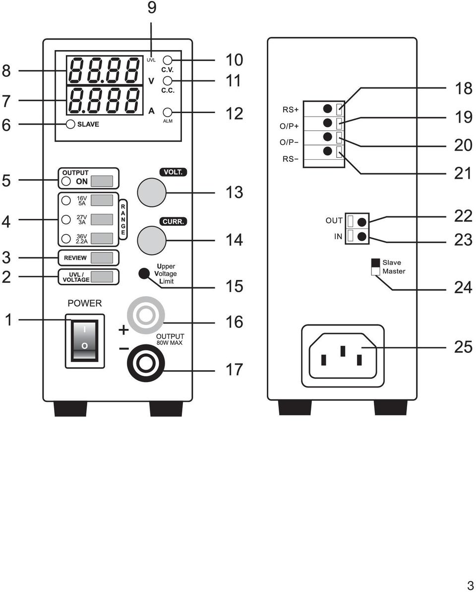
6 Bedienelemente (siehe Ausklappseite) (1) Netzschalter zur Inbetriebnahme (I = Ein / 0 = Aus) (2) UVL-Taste zur Aktivierung der Limit-Einstellung (3) REVIEW-Taste zur Anzeige der Spannungs- und Stromeinstellung (4) Bereichswahltasten für den entsprechenden DC-Ausgangsbereich (5) OUTPUT ON-Taste zum Aktivieren und Deaktivieren des DC-Ausganges (6) SLAVE-Statusanzeige leuchtet im Slave-Betrieb (7) LED-Anzeige für die Stromstärke Ampere (8) LED-Anzeige für die Spannung Volt (9) UVL-Statusanzeige bei aktiver UVL-Limiteinstellung (10) C.V.-Statusanzeige für Konstantspannung (11) C.C.-Statusanzeige bei aktiver Strombegrenzung (12) ALM-Statusanzeige bei deaktiviertem Ausgang durch die UVL-Limiteinstellung (13) Einstellregler für Spannung (14) Einstellregler für die Strombegrenzung (max. zulässiger Strom) (15) Einstellpunkt für den UVL-Limitwert (bei aktivierter UVL-Limit-Einstellung) (16) Anschlussbuchse Pluspol (17) Anschlussbuchse Minuspol (18) Steckklemme für Sense-Leitung zur Fernfühlung, Pluspol (19) Steckklemme für alternativen DC-Ausgang, Pluspol (20) Steckklemme für alternativen DC-Ausgang, Minuspol (21) Steckklemme für Sense-Leitung zur Fernfühlung, Minuspol (22) Steckklemme für Masterbetrieb-Ausgang (23) Steckklemme für Slave-Betrieb-Eingang (24) Master/Slave-Umschalter (25) Schutzkontakt-Kaltgeräteanschluss für Netzkabel 6
 ALM-Statusanzeige bei deaktiviertem Ausgang durch die UVL-Limiteinstellung (13) Einstellregler für Spannung (14) Einstellregler für die")
7 Sicherheits- und Gefahrenhinweise Bei Schäden, die durch Nichtbeachten dieser Bedienungsanleitung verursacht werden, erlischt die Gewährleistung/Garantie! Für Folgeschäden und bei Sachoder Personenschäden, die durch unsachgemäße Handhabung oder Nichtbeachten der Sicherheitshinweise verursacht werden, übernehmen wir keine Haftung! Dieses Gerät hat das Werk in sicherheitstechnisch einwandfreien Zustand verlassen. Um diesen Zustand zu erhalten und einen gefahrlosen Betrieb sicherzustellen, muss der Anwender die Sicherheitshinweise und Warnvermerke beachten, die in dieser Gebrauchsanweisung enthalten sind. Folgende Symbole gilt es zu beachten: Ein Ein in einem Dreieck befindliches Ausrufezeichen weist auf wichtige Hinweise in dieser Bedienungsanleitung hin, die unbedingt zu beachten sind. Blitzsymbol im Dreieck warnt vor einem elektrischen Schlag oder der Beeinträchtigung der elektrischen Sicherheit des Geräts. Das Hand -Symbol ist zu finden, wenn Ihnen besondere Tipps und Hinweise zur Bedienung gegeben werden sollen. Nur zur Verwendung in trockenen Innenbereichen Dieses Gerät ist CE-konform und erfüllt die erforderlichen nationalen und europäischen Richtlinien. Schutzleiteranschluss; diese Schraube darf nicht gelöst werden Elektrogeräte und Zubehör sind keine Spielzeuge und gehören nicht in Kinderhände! In gewerblichen Einrichtungen sind die Unfallverhütungsvorschriften des Verbandes der gewerblichen Berufsgenossenschaften für elektrische Anlagen und Betriebsmittel zu beachten. In Schulen und Ausbildungseinrichtungen, Hobby- und Selbsthilfewerkstätten ist der Umgang mit Netzgeräten durch geschultes Personal verantwortlich zu überwachen. Achten Sie darauf, dass ihre Hände, Schuhe, Kleidung, der Boden und das Netzgerät unbedingt trocken sind. 7

8 Beim Öffnen von Abdeckungen oder entfernen von Teilen, außer wenn dies von Hand möglich ist, können spannungsführende Teile freigelegt werden. Vor einem Öffnen, muss das Gerät von allen Spannungsquellen getrennt werden. Kondensatoren im Gerät können noch geladen sein, selbst wenn das Gerät von allen Spannungsquellen getrennt wurde. Schalten Sie das Labornetzgerät niemals gleich dann ein, wenn es von einem kalten in einen warmen Raum gebracht wird. Das dabei entstandene Kondenswasser kann unter ungünstigen Umständen Ihr Gerät zerstören. Lassen Sie das Gerät uneingeschaltet auf Zimmertemperatur kommen. Das Schaltnetzgerät erwärmt sich bei Betrieb; Achten Sie auf eine ausreichende Belüftung. Lüftungsschlitze dürfen nicht abgedeckt werden! Stellen Sie keine Flüssigkeiten auf dem Gerät ab. Netzgeräte und die angeschlossenen Verbraucher dürfen nicht unbeaufsichtigt betrieben werden. Bei Arbeiten mit Netzgeräten ist das Tragen von metallischem oder leitfähigem Schmuck wie Ketten, Armbändern, Ringen o.ä. verboten. Das Netzgerät ist nicht für die Anwendung an Menschen und Tieren zugelassen. Setzen Sie das Gerät keinen mechanischen Beanspruchungen aus. Bereits der Fall aus geringer Höhe kann das Gerät beschädigen. Vibrationen und direktes Sonnenlicht sind zu vermeiden. Wenn anzunehmen ist, dass ein gefahrloser Betrieb nicht mehr möglich ist, so ist das Gerät außer Betrieb zu setzen und gegen unbeabsichtigten Betrieb zu sichern. Es ist anzunehmen, dass ein gefahrloser Betrieb nicht mehr möglich ist, wenn: - das Gerät sichtbare Beschädigungen aufweist, - das Gerät nicht mehr arbeitet und - nach längerer Lagerung unter ungünstigen Verhältnissen oder - nach schweren Transportbeanspruchungen. Beachten Sie auch die Sicherheitshinweise in den einzelnen Kapiteln bzw. in den Bedienungsanleitungen der angeschlossenen Geräte. 8

9 Funktionsbeschreibung Das Labornetzgerät arbeitet mit hochentwickelter Schaltnetzteiltechnologie und aktiver PFC (Leistungsfaktor-Korrektur). Dies ermöglicht eine stabile Ausgangsspannung sowie einen hohen Wirkungsgrad. Der Gleichspannungsausgang ist galvanisch getrennt und weist eine Schutztrennung gegenüber der Netzspannung auf. Sekundärseitig erfolgt der DC-Anschluss frontseitig über zwei farbige Sicherheits- Buchsen und rückseitig über Steckklemmen. Die beiden Ausgänge sind direkt miteinander verbunden. Im übersichtlichen Dual-Display erfolgt die Spannungs- und Stromanzeige (V = Volt = Einheit der elektrischen Spannung, A = Ampere = Einheit der elektrischen Stromstärke). Über Leuchtanzeigen wird der aktuelle Zustand des Netzgerätes signalisiert. Diverse Schutzmechanismen, z.b. Überlastschutz, Strombegrenzung, Überhitzungsschutz etc. sind für den sicheren und zuverlässigen Betrieb eingebaut. Die Kühlung des Netzgerätes erfolgt über Konvektion. Auf eine ausreichende Luftzirkulation ist deshalb zu achten. Ausgangsspannung und Ausgangsstrom sind stufenlos einstellbar. Lieferumfang Labornetzgerät Netzkabel Bedienungsanleitung 9
.")
10 Inbetriebnahme Das Labornetzgerät ist kein Ladegerät. Verwenden Sie zum Laden von Akkus geeignete Ladegeräte mit entsprechender Ladeabschaltung. Bei längerem Betrieb mit Nennlast wird die Gehäuseoberfläche warm. Achtung! Mögliche Verbrennungsgefahr! Achten Sie daher unbedingt auf eine ausreichende Belüftung des Netzgerätes und betreiben Sie es niemals teilweise oder ganz abgedeckt, um eventuelle Schäden zu vermeiden. Achten Sie beim Anschluss eines Verbrauchers unbedingt darauf, dass dieser im nicht eingeschalteten Zustand angeschlossen wird. Ein eingeschalteter Verbraucher kann beim Anschluss an die Ausgangsbuchsen des Netzgerätes zu einer Funkenbildung führen, welche wiederum die Buchsen bzw. die angeschlossenen Leitungen und/oder deren Klemmen beschädigen können. Wenn Sie Ihr Netzgerät nicht benötigen, trennen Sie es vom Netz. Anschluss des Netzkabels Verbinden Sie das beiliegende Schutzkontakt-Netzkabel mit dem Kaltgeräte-Einbaustecker (25) am Netzgerät. Achten Sie auf festen Sitz. Verbinden Sie das Netzkabel mit einer Schutzkontakt-Steckdose mit Schutzerdung. Aufstellen des Gerätes Stellen Sie das Labornetzgerät auf eine stabile, ebene und unempfindliche Oberfläche ab. Achten Sie darauf, dass die Lüftungsschlitze im Gehäuse nicht verdeckt werden. Einschalten Schalten Sie das Labornetzgerät am Netzschalter (1) ein. Das Netzgerät führt für ca. 1-2 Sekunden einen stillen Systemcheck (keine Anzeigen) durch und zeigt das Ergebnis anschließend durch das Aufleuchten sämtlicher Anzeigen (außer OUTPUT ON und SLAVE ). Wird im Doppeldisplay 0000 angezeigt, ist das Labornetzgerät einsatzbereit. Voreinstellung der oberen Spannungsgrenze Ihr Labornetzgerät verfügt über diverse Schutzmaßnahmen, um angeschlossenen Verbraucher vor einem Schaden durch Fehlfunktion (z.b. erhöhte Stromaufnahme des Verbrauchers) oder Überspannung (falsch eingestellte Ausgangsspannung) zu schützen. Diese Schutzparameter müssen vorab auf Ihre Anforderungen eingestellt werden, können aber zu jeder Zeit verändert werden. 10

11 UVL-Spannungsbegrenzung Die UVL-Funktion ermöglicht die Einstellung der oberen Spannungsgrenze. Wird diese Spannungsgrenze überschritten, so schaltet der DC-Ausgang automatisch ab und signalisiert dies durch die Leuchtanzeige ALM (12). Reduzieren Sie die Ausgangsspannung. Zum Aktivieren des DC-Ausgangs betätigen Sie die Taste OUTPUT ON (5). Die Warnanzeige ALM erlischt. Zur Einstellung gehen Sie wie folgt vor: - Schalten Sie das Labornetzgerät ein und warten ca. 1-2 Sekunden. - Drücken Sie die Taste UVL/Voltage (2). Die Statusanzeige UVL (9) leuchtet. - In der Anzeige V (8) wird die derzeitige Spannungsgrenze angezeigt. - Führen Sie vorsichtig einen kleinen Schlitzschraubendreher (Klingenbreite max. 3 mm) in die Öffnung Upper Voltage Limit (15). Stellen Sie vorsichtig den gewünschten Spannungswert über den inneren Feinregler ein. - Durch erneutes Drücken der Taste UVL (5) verlassen Sie diesen Einstellbereich. Die Anzeige (9) erlischt. Der eingestellte Wert bleibt auch nach dem Ausschalten erhalten. Spannung und Strom einstellen Das Labornetzgerät ermöglicht die Einstellung von Spannung und Strombegrenzung auch bei abgeschaltetem Ausgang. Der Vorteil liegt daran, dass zur Einstellung der Strombegrenzung kein Kurzschluss am Ausgang simuliert werden muss. Die Einstellung des Ausgangsstromes ist ein Schutzmechanismus, um den Verbraucher oder die Anschlussleitungen zu schützen. Zur Einstellung gehen Sie wie folgt vor: - Schalten Sie das Labornetzgerät ein und warten ca. 1-2 Sekunden. - Wählen Sie den gewünschten Ausgangsbereich über die Tasten RANGE (4). Die entsprechende Statusanzeige leuchtet. Aus Sicherheitsgründen wird bei jeder Bereichsumschaltung der aktive DC-Ausgang deaktiviert. - Drücken und halten Sie für die Dauer der Einstellung die Taste REVIEW (3) gedrückt. - In der Anzeige erscheint die Spannungs- und Stromeinstellung für den aktivierten DC-Ausgang. - Über den Einstellregler VOLT. (13) erfolgt die Spannungswahl. - Über Einstellregler CURR. (14) erfolgt die Strombegrenzung. - Lassen Sie die Taste REVIEW (3) los. Das Display zeigt wieder Bei aktivem Ausgang ist die Spannungseinstellung direkt möglich. 11
. Die Statusanzeige UVL (9) leuchtet. - In der Anzeige V (8) wird die derzeitige Spannungsgrenze angezeigt.")
12 Anschluss eines Verbrauchers Achten Sie beim Anschluss eines Verbrauchers darauf, dass dieser uneingeschaltet mit dem Netzgerät verbunden wird. Die max. Stromaufnahme des anzuschließenden Verbrauchers darf die Angaben in den technischen Daten nicht überschreiten. Bei der Reihenschaltung mehrerer Netzgeräte werden berührungsgefährliche Spannungen(> 70 VDC) erzeugt, welche bei Berührung lebensgefährlich sein können. Ab dieser Spannung darf nur schutzisoliertes Zubehör (Anschlussleitungen, Messleitungen etc.) verwendet werden. Die Verwendung metallisch blanker Leitungen und Kontakte ist zu vermeiden. Alle diese Stellen sind durch geeignete, schwer entflammbare Isolierstoffe oder andere Maßnahmen abzudecken und vor direkter Berührung und Kurzschluss zu schützen. Achten Sie auf einen ausreichenden Leiterquerschnitt für die vorgesehene Stromstärke. Normalbetrieb Master Im Master-Normalbetrieb erfolgt die Steuerung über die beiden Einstellregler für Spannung und Strom. Eine Steuerung durch andere Geräte ist nicht möglich. Schalten Sie das Netzgerät über den Betriebsschalter (1) ein. Die Spannungs- und Stromanzeige (7 und 8) erscheinen nach ca. 1-2 Sekunden und zeigen Stellen Sie die Parameter nach Ihren Vorgaben wie im Kapitel Inbetriebnahme beschrieben ein. Kontrollieren Sie nochmals die korrekt eingestellte Ausgangsspannung durch Drücken der Taste REVIEW (3). Verbinden Sie den Pluspol (+) des Verbrauchers mit der roten Buchse + (16) und den Minuspol (-) mit der schwarzen Buchse - (17). Alternativ kann auch der Anschluss über die rückseitigen Steckklemmen erfolgen. Drücken Sie dazu mit einem Schraubendreher die kleine Nut nach innen und führen den abisolierten Leiter in die runde Öffnung. Der Pluspol entspricht Klemme O/P+ (19), der Minuspol entspricht Klemme O/P- (20). Das Entriegeln erfolgt auf die gleiche Weise. Aktivieren Sie den DC-Ausgang durch Drücken der Taste OUTPUT ON (5). Die Statusanzeige (5) leuchtet und im Display (8) wird die Ausgangsspannung angezeigt. Der angeschlossene Verbraucher kann jetzt eingeschaltet werden. Die Stromaufnahme des angeschlossenen Verbrauchers wird in der Stromanzeige A im Display (7) angezeigt. 12
 verwendet werden. Die Verwendung metallisch blanker Leitungen und Kontakte ist zu vermeiden.")
13 Der Ausgang kann durch einfaches Drücken der Taste OUTPUT ON (5) deaktiviert werden. Im normalen Betrieb arbeitet das Gerät im Konstantspannungsmodus. Das heißt, das Netzgerät gibt eine konstante voreingestellte Ausgangsspannung ab. Dieser Betrieb wird mit der grünen Statusanzeige C.V. (10) signalisiert. Wird die voreingestellte Stromstärke im Normalbetrieb erreicht, schaltet das Netzgerät in den Strombegrenzungsmodus und reduziert dabei den Spannungswert. Dieser Betrieb wird mit der roten Statusanzeige C.C. (11) signalisiert. Master-/Slave-Betrieb Im Master-/Slave-Betrieb können bis zu 4 Labornetzgeräte vom Typ LSP 1403 über das Master -Netzgerät gesteuert werden. Die Steuerung erfolgt hierbei für Spannung und Strom. Zum Anschluss gehen Sie wie folgt vor: Schalten Sie die Geräte ein und stellen Sie alle Netzgeräte auf den selben UVL -Pegel (2) und den selben Ausgangsbereich (4) ein. Stellen Sie die Spannungs- und Stromregler der Slave -Geräte auf Maximum (Rechtsanschlag). Schalten Sie alle Netzgeräte am Betriebsschalter (1) aus. Stellen Sie den rückseitigen Master-/Slave-Wahlschalter (24) in die entsprechende Position. Das Hauptgerät (Master) wird in Schalterstellung Master gebracht. Alle weiteren Geräte müssen in Position Slave gestellt werden. Verbinden Sie die Netzgeräte mit einem Schaltdraht gleicher Länge und Querschnitt, beginnend von Netzgerät Master am Klemmkontakt OUT (22). Drücken Sie dazu mit einem Schraubendreher die kleine Nut nach innen und führen den abisolierten Leiter in die runde Öffnung. Führen Sie den Schaltdraht weiter zum nächsten Netzgerät und Kontaktieren diesen an der Klemme IN (23). Sind weitere Netzgeräte im Regelkreis, so führen Sie die Anschlussfolge fort (Siehe folgende Skizze). Kontrollieren Sie nochmals die Reglerstellung Maximal der Slave-Geräte. Schalten Sie immer erst das Master-Netzgerät ein und wählen die gewünschte Ausgangsspannung. Wenn dieses betriebsbereit ist, können alle weiteren Geräte folgen. Die Slave-Geräte zeigen den Slave-Betrieb über die Statusanzeige SLAVE (6) an. Im Master-/Slave-Betrieb muss immer ein geringer Strom (ca. 5% vom Nennstrom) am Ausgang fließen, um den Regelkreis durch das Master-Gerät aufrecht zu halten. Stellen Sie dies durch eine kleine abnehmbare Last am Ausgang sicher (z.b. Lastwiderstand 1 KOhm). 13
 signalisiert.")
14 Der Anschluss kann wie Abgebildet an den frontseitigen Buchsen oder an den rückseitigen Steckklemmen (19/20) erfolgen. Aktivieren Sie alle DC-Ausgänge mit der Taste OUTPUT ON. Alle Ausgangsspannungen und Ströme werden über das Master -Gerät gesteuert. Fühlerbetrieb Sense Der Fühlerbetrieb Sense ermöglicht die präzise Spannungseinstellung direkt am Verbraucher. Ein möglicher Spannungsabfall über die Anschlussleitungen wird so zuverlässig kompensiert. Der Fühlerbetrieb ist nur im Normalbetrieb (Master) möglich. Schalten Sie das Netzgerät aus. Verbinden Sie den Verbraucher polungsrichtig mit den Ausgangsbuchsen oder den Steckklemmen (O/P) am Netzgerät. Verbinden Sie die Fühlerleitung polungsrichtig von den Anschlussklemmen des Verbrauchers mit dem Fühlereingang am Netzgerät. Die Plusleitung muss an Klemme RS+ (18) und die Minusleitung an Klemme RS- (21) angeschlossen werden. Drücken Sie dazu mit einem Schraubendreher die kleine Nut nach innen und führen den abisolierten Leiter in die runde Öffnung. Schalten Sie das Netzgerät über den Betriebsschalter (1) ein. Nach einer kurzen Initialisierungsphase erscheint die Spannungsund Stromanzeige. Stellen Sie die Parameter nach Ihren Vorgaben wie im Kapitel Inbetriebnahme beschrieben ein. Kontrollieren Sie nochmals die korrekt eingestellte Ausgangsspannung und aktivieren Sie den DC-Ausgang mit der Taste OUTPUT ON. Der angeschlossene Verbraucher kann jetzt eingeschaltet werden 14
 am Netzgerät.")
15 . Entfernen Sie beim Abklemmen des Verbrauchers immer erst die Versorgungsleitungen oder schalten das Labornetzgerät aus, bevor Sie die Fühlerleitungen abklemmen. Erfolgt dies nicht, kann die Ausgangsspannung bis zum Maximum ansteigen und ggf. Ihren Verbraucher beschädigen. Entsorgung Elektronische Altgeräte sind Wertstoffe und gehören nicht in den Hausmüll. Ist das Gerät am Ende seiner Lebensdauer, so entsorgen Sie es nach den geltenden gesetzlichen Bestimmungen bei den kommunalen Sammelstellen. Eine Entsorgung über den Hausmüll ist untersagt. Wartung und Reinigung Bis auf eine gelegentliche Reinigung ist das Labornetzgerät wartungsfrei. Zur Reinigung des Gerätes nehmen Sie ein sauberes, fusselfreies, antistatisches und trockenes Reinigungstuch ohne scheuernde, chemische und lösungsmittelhaltige Reinigungsmittel. Behebung von Störungen Mit dem Labornetzgerät haben Sie ein Produkt erworben, welches zuverlässig und betriebssicher ist. Dennoch kann es zu Problemen oder Störungen kommen. Hier möchten wir Ihnen beschreiben, wie Sie mögliche Störungen leicht selbst beheben können: Beachten Sie unbedingt die Sicherheitshinweise! Fehler Mögliche Ursache Das Netzgerät lässt sich Leuchten am Netzgerät die Anzeigen (7/8)? nicht einschalten. Kontrollieren Sie die Netzspannung (evtl. Netzstecker locker bzw. Leitungsschutzschalter überprüfen). Warten Sie ca. 1-2 Sekunden. Die stille Initialisierung erfolgt ohne Anzeigen. Nach dem Einschalten dauert Die elektronische Regelung benötigt diese Zeit, um alle internen es ca. 1-2 Sekunden, bis Funktionen zu überprüfen. Dies ist keine Fehlfunktion. eine Anzeige erscheint. 15

16 Fehler Mögliche Ursache Der angeschlossene Ist die korrekte Spannung eingestellt? Verbraucher funktioniert nicht. Ist die Polarität korrekt? Kontrollieren Sie die technischen Daten des Verbrauchers. Der DC-Ausgang ist nicht aktiv? Die ALM -Anzeige leuchtet. Der voreingestellte Spannungspegel (UVL) wurde überschritten. Reduzieren Sie die Spannungseinstellung und aktivieren Sie den Ausgang. Die C.C. -Anzeige leuchtet. Die voreingestellte Stromstärke wurde überschritten. Kontrollieren Sie die Stromaufnahme an Ihrem Verbraucher und erhöhen Sie ggf. die Strombegrenzung am Netzgerät. Die UVL -Anzeige leuchtet Sie befinden Sich im UVL-Einstellmenü. Drücken Sie für den Normalbetrieb die Taste UVL/VOLTAGE (2). Die Ausgangsspannung stimmt Sie befinden Sich im UVL-Einstellmenü. Kontrollieren Sie, ob die nicht mit der Anzeige überein. Anzeige UVL leuchtet. Drücken Sie für den Normalbetrieb die Taste UVL/VOLTAGE (2). Die Stromanzeige zeigt Das Gerät befindet sich im Slave-Modus, obwohl kein Master unsinnige Werte. angeschlossen ist. Stellen Sie den rückseitigen Schiebeschalter (24) in Position Master. Das Netzgerät schaltet sich Die elektronische Regelung benötigt diese Zeit, um alle erst nach ca. 3 Sekunden ab. Kondensatoren im Inneren zu entladen. Dies ist keine Fehlfunktion. Überprüfen Sie regelmäßig die technische Sicherheit des Gerätes z.b. auf Beschädigung des Gehäuses usw. Eine andere Reparatur darf nur durch eine Fachkraft erfolgen, die mit den damit verbundenen Gefahren bzw. einschlägigen Vorschriften vertraut ist. Bei eigenmächtigen Änderungen oder Reparaturen am oder im Gerät, erlischt der Garantieanspruch. Sicherungen sind Ersatzteile und werden nicht durch die Garantie abgedeckt. 16
. Die Ausgangsspannung stimmt Sie befinden Sich im UVL-Einstellmenü.")
17 Technische Daten Ausgangsleistung max. 80 VA Ausgangsbereich V/DC, 0-5 A Ausgangsbereich V/DC, 0-3 A Ausgangsbereich V/DC, 0-2,2 A Restwelligkeit bei Nennlast < 30 mvpp Spannungs-Regelverhalten bei 100% Laständerung < 20 mv Spannungs-Regelverhalten bei 10% Netzschwankung..... < 4 mv Strom-Regelverhalten bei 100% Laständerung < 10 ma Strom-Regelverhalten bei 10% Netzschwankung < 10 ma Genauigkeit der Spannungs- und Stromanzeige /-(1% + 2 Counts) Wirkungsgrad >75 % Betriebsspannung V 50/60 Hz Stromaufnahme (max.) < 0,5 A Betriebstemperatur bis +40 C Rel. Luftfeuchtigkeit max. 80%, nicht kondensierend Betriebshöhe max m Schutzklasse Netzanschluss Kaltgeräte-Einbaustecker, IEC 320 C14 Gewicht ,65 kg Abmessungen (B x H x T) mm x 137 x
 Wirkungsgrad..................................... >75 % Betriebsspannung.")
18 Introduction Dear customer, Thank you for making the excellent decision to purchase this Voltcraft product. You acquired a high-quality product with a name that stands for outstanding products in the field of measuring, charging and power technology, which excel by professional competence and permanent innovation. The products of the Voltcraft family offer optimum solutions even for the most demanding applications for ambitious hobby electricians as well as for professional users. Voltcraft offers reliable technology with an exceptional cost-performance ration. Therefore, we are absolutely sure: Your starting to use Voltcraft will also be the beginning of a long, successful relationship. We hope you will enjoy using your new Voltcraft product! Table of Contents Introduction...18 Intended Use...19 Operating elements...20 Safety and Hazard Notices...21 Functional description...23 Contents...23 Initial operation...24 Connecting the power cable...24 Setting up the device...24 Switching on...24 Presetting the top voltage limit...24 Setting the voltage and the current...25 Connecting a device...26 Normal operation master...26 Master/slave operation...27 Sensor operation sense...28 Disposal...29 Maintenance and cleaning...29 Troubleshooting...29 Technical data

19 Intended Use The laboratory power supply unit serves as a potential-free DC voltage source to operate low-voltage consumers. You have the choice between three adjustable output ranges (from 0-16 V, 0-27 V or 0-36 V). The maximum output in all three ranges is 80 Watt. The DC output can be realised alternatively on the front of the device via 4 mm safety sockets or on the back via plug-in clamps. Voltage drops in the DC line can be compensated and stabilised via a sense line. Master/slave control for voltage an current is possible when using several LSP-1403 laboratory power supplies. All additional laboratory power supplies are controlled via the master power supply unit. Parallel switching at the DC output (current multiplication). An adjustable voltage limit protects connected consumers from accidental overvoltage. If this voltage limit is reached, the output is deactivated. Via a preview function, you can set and control the output voltage and the current limitation. The voltage and current strength is shown on the dual display and can be controlled continuously. The laboratory power supply is designed in compliance with protection class 1. It is only approved for connection to shockproof sockets with protective grounding and an alternating current from 100 to 240V/AC commonly used in households. Do not use in adverse ambient conditions. Unfavourable ambient conditions are: - Excessive humidity or dampness - Dust and combustible gases, vapours or solvents. - Thunderstorms or similar conditions such as strong electrostatic fields etc. Any use other than the one described above damages the product. Moreover, this involves dangers such as e.g. short circuit, fire, electric shock, etc. No part of the product must be modified or rebuilt! Observe the safety instructions under all circumstances! When switching several laboratory power supplies in series, voltages of >70 V/DC may be generated, which are dangerous to contact. This is why insulated lines/measuring cables must be used for safety reasons as of this voltage. 19

20 Operating elements (see fold-out page) (1) Power switch for putting the device into operation (I=ON / 0=OFF) (2) UVL button for activating the limit setting (3) REVIEW button for displaying the voltage and current setting (4) Range selection buttons for the corresponding DC output range (5) OUTPUT ON button for activating and deactivating the DC output (6) SLAVE status display is lit in slave operation (7) LED display for the current strength Ampere (8) LED display for the voltage Volt (9) UVL status display with active UVL limit setting (10) C.V. status display for constant voltage (11) C.C. status display in case of active current limitation (12) ALM status display in case of deactivated output due to UVL limit setting (13) Adjuster for the voltage (14) Adjuster for the current limitation (max. admissible current) (15) Adjustment position for the UVL limit value (with activated UVL limit setting) (16) Connection socket positive pole (17) Connection socket negative pole (18) Plug-in clamp for sense line for remote sensing, positive pole (19) Plug-in clamp for alternative DC output, positive pole (20) Plug-in clamp for alternative DC output, negative pole (21) Plug-in clamp for sense line for remote sensing, negative pole (22) Plug-in clamp for master operation output (23) Plug-in clamp for slave operation input (24) Master-slave conversion switch (25) Grounded low-power connection for mains cable 20
 ALM status display in case of deactivated output due to UVL limit setting (13) Adjuster for the voltage (14) Adjuster for the current")
21 Safety and Hazard Notices The warranty/guarantee will be void in the event of damage caused by failure to observe these safety instructions! We do not accept liability for damage to property or injury to persons caused by misuse or non-compliance with the safety instructions! This device left the manufacture s factory in a safe and perfect condition. We kindly request that you as a user observe the safety instructions and warnings contained in this operating manual to preserve this condition and to ensure safe operation! Please pay attention to the following symbols: A The triangle containing an exclamation mark indicates important information in these operating instructions which are to be observed without fail. triangle containing a lightning symbol warns of danger of an electric shock or of the impairment of the electrical safety of the device. The hand symbol is used to indicate where specific hints and information on handling are given. Only to be used in dry indoor areas. This product has been CE-tested and meets the necessary European guidelines. Earth wire connection; this screw may not be slackened Electrical appliances and accessories are not toys and have no place in the hands of children. On industrial sites the accident prevention regulations of the association of the industrial workers society for electrical equipment and utilities must be followed. Power supply units used at schools, training facilities, do-it-yourself and hobby workshops should not be handled unless supervised by trained, responsible personnel. Please make sure that your hands, your shoes, your clothing, the floor and the power supply unit are dry. 21
22 Live components may be exposed if covers are opened or parts are removed (unless this can be done without tools). Before opening it, disconnect the device from all voltage sources. Capacitors inside the device may still be charged, even if the device has been disconnected from all voltage sources. Do not switch the laboratory power pack unit on immediately after it has been taken from a cold to a warm environment. Condensation water that forms might destroy your device. Allow the device to reach room temperature before switching it on. The switched-mode mains power supply generates heat during operation. Make sure it is adequately ventilated. Do not cover the ventilation apertures of the device! Do not place any vessels with liquids on the device Do not leave mains power supplies and the connected consumers in operation unattended. When working with power supplies wearing metallic or conductive jewellery, such as necklaces, bracelets, rings etc., is prohibited. The power supply unit is not designed for application to human beings or animals. Never expose the device to mechanical stress. Dropping the device even from a low height may damage it! Avoid vibrations and direct sunlight. If you have a reason to believe that the device can no longer be operated safely, disconnect it immediately and secure it against being operated unintentionally. It can be assumed that safe operation is no longer possible if: - the device is visibly damaged, - the device no longer works and - the unit was stored under unfavourable conditions for a long period of time or - if it has been subjected to considerable stress in transit. You should also heed the additional safety instructions in each chapter of the operating instructions of the connected devices. 22
23 Functional description The laboratory power supply works with highly developed combinational circuit technology and active PFC (power factor correction). This ensures a stable output voltage and a high degree of effectiveness. The DC output is electrically isolated and features a protective isolation towards the mains voltage. The secondary DC connection is realised via two coloured safety sockets on the front and via plug-in clamps on the rear. Both outputs are directly connected to each other. The concise dual displays show the voltage and current (V = Volt = unit of electric voltage, A = Ampere = unit of electric current). Via light displays the current condition of the power supply is indicated. Various protective mechanisms, e.g. overload protection, current limitation, overheating protection, etc. are built in for secure and reliable operation. The power supply unit is cooled through convection. Therefore, ensure sufficient air circulation. Output voltage and output current can be adjusted continuously. Contents Laboratory power unit Power cable Operating instructions 23
24 Initial operation The laboratory power supply is not a charger. To charge batteries, use suitable chargers with a charging current cut-off. During a longer period of operation under nominal load, the surface of the housing will heat up. Attention! Risk of burns! Therefore, make sure that there is adequate ventilation of the power unit and never operate it partly or fully covered to avoid any damage. When connecting a consumer ensure that it is not connected when switched on. A switched on consumer can result in sparks when connecting to the output terminals of the power supply, which in turn can damage the sockets or the connected cables and/or their clamps. If your power supply is not required, disconnect it from the mains. Connecting the power cable Connect the supplied earthing mains cable to the low-power device installation socket (25) on the power supply. Ensure a tight fit. Connect the power cable to a shockproof mains socket with protective grounding. Setting up the device Place the laboratory power supply on a stable, level and robust surface. Make sure that ventilation slots in the casing are not covered up. Switching on Switch on the power unit on the mains switch (1). The power unit performs a silent system check for approx. 1 to 2 seconds (no display) and then indicates the result by illuminating all displays (except for OUTPUT ON and SLAVE ). If the dual display shows 0000, the laboratory power unit is ready for operation. Presetting the top voltage limit Your laboratory power unit features various protective measures to protect consumers from damage due to malfunctioning (e.g. increased current consumption of the consumer) or overvoltage (wrongly set output voltage). You have to adjust these protective parameters according to your requirements and you can also change them at any time. 24
25 UVL voltage limitation The UVL function allows you to set the top voltage limit. If this voltage limit is exceeded, the DC output cuts off automatically and signals this with the indicator light ALM (12). Reduce the output voltage. To activate the DC output, press the button OUTPUT ON (5). The warning indicator ALM goes off. To program, proceed as follows: - Turn the laboratory power unit on and wait approx. 1-2 seconds. - Press the button UVL/Voltage (2). The status display UVL (9) is lit. - The display V (8) shows the current voltage limit. - Carefully insert a small screwdriver (blade width max. 3 mm) into the opening Upper Voltage Limit (15). Carefully set the desired voltage limit via the internal precision regulator. - You leave the setup range by again pressing the button UVL (5). The indicator (9) will go off. The set value is preserved even when turning the device off. Setting the voltage and the current The laboratory power unit also allows you to set the voltage and current limit when the output is switched off. The advantage is that you do not have to simulate a short circuit at the output to adjust the current limit. Setting the output current is a protection mechanism to protect the consumer or connection cables. To program, proceed as follows: - Turn the laboratory power unit on and wait approx. 1-2 seconds. - Select the desired output range via the buttons RANGE (4). The corresponding LED lights up. For safety reasons, the active DC output is deactivated at each range switch. - Press and hold the button REVIEW (3) for the duration of the setup operation. - The display shows the voltage and current setting for the activated DC output. - Select the voltage via the adjuster VOLT (13). - The current limitation is realised via the adjuster CURR (14). - Let go of the button REVIEW (3). The display then shows 0000 again. - Direct voltage setting is possible with an active output. 25
26 Connecting a device When connecting a consumer, make sure that it is connected to the power supply when switched off. The maximum current consumption of the device to be connected must not exceed the capacity indicated in the technical specifications. For series connection of several power supplies, contact dangerous voltages (> 70 VDC) are created where contact can be fatal. As of this voltage, you may only use insulated accessories. Avoid the use of non-insulated metallic cables and contacts. All these spots must be covered with suitable, flame-resistant insulation materials or by means of other measures, which serve to prevent direct contact and short circuits. Ensure a sufficient cable diameter for the intended current. Normal operation master In normal master operation, the device is controlled using the two adjusters for voltage and current. Control through other devices is not possible. Switch on the mains power supply at the power switch (1). The voltage and power display (7 and 8) appear after approx. 1 to 2 seconds and show Set the parameters according to your specifications as described in the chapter Commissioning. Check once again that the output voltage is set correctly by pressing the button REVIEW (3). Connect the positive terminal (+) of the load with the red socket + (16) and the negative terminal with the black socket - (17). Alternatively, you can also realise the connection via the plug-type clamps on the back. To do so, press the little slot inwards with a screwdriver and insert the insulated conductor into the round opening. The positive pole corresponds to the clamp O/P+ (19), the negative pole to the clamp O/P- (20). Unlatching is done the same way. Activate the DC output by pressing the button OUTPUT ON (5). The status LED is lit (5) and the display (8) shows the output voltage. Now you can switch on the connected consumer. The current consumption of the connected consumer is displayed on the power display A (7). 26
27 The output can be deactivated by pressing the button OUTPUT ON (5). In normal mode the device operates in constant voltage mode. This means that the power supply emits a constant, preset output voltage. This operation is indicated with a green status display CV (10). If the preset current is reached in normal operation, the power supply switches to current limitation mode and reduces the voltage value. This operation is indicated with a red status display CC (11). Master/slave operation In master/slave operation, you can control up to 4 laboratory power units type LSP 1403 via the master power unit. The voltage and the current are controlled here. Proceed as follows for connection: Turn the device on and set all power units to the same UVL level (2) and the same output range (4). Set the voltage and the current control of the slave devices to maximum (all the way to the right). Switch on the power unit on the operating switch (1). Put the master/slave selection switch (24) on the rear into the corresponding position. The main device (master) is set to the switch position master. All other devices must be set in the position slave. Connect the power units with a jumper wire of the same length and diameter on the clamp contact OUT (22) starting with the master power unit. To do so, press the little slot inwards with a screwdriver and insert the insulated conductor into the round opening. Guide the jumper wire on to the next power unit and connect it to the clamp IN (23). If there are additional power units in the circuit, continue the connection sequence (see the following sketch). Check the control setting Maximum of the slave devices once again. Always turn the master power unit on first and select the desired output voltage. Once this is ready for operation, you can activate all other devices. The slave devices indicated slave operation via the status LED SLAVE (6). In master/slave operation, a slight current (approx. 5% of the nominal current) must always be applied to the output to maintain the control circuit via the master device. Ensure this with a small detachable load at the output (e.g. load resistance 1 KOhm). 27
28 You can establish the connection as illustrated at the front sockets or with the plug clamps on the back (19/20). Activate all DC outputs with the button OUTPUT ON. All output voltages and currents are controlled via the master device. Sensor operation sense The sensor operation sense allows the precise voltage setting directly on the consumer. This reliably compensates a possible voltage drop via the connection cables. Sensor operation is only possible in normal (master) mode. Switch the power unit off. Connect the consumer with the output sockets (observe the correct polarity!) or the plug clamps (O/P) on the power unit. Connect the sensor cable from the connection clamps of the consumer with the sensor input on the power supply observing the right polarity. The positive lead must be connected to the clamp RS+ (18) and the negative lead to the clamp RS - (21). To do so, press the little slot inwards with a screwdriver and insert the insulated conductor into the round opening. Switch on the mains power supply at the power switch (1). The voltage and current display appears after a short initiation period. Set the parameters according to your specifications as described in the chapter Commissioning. Check once again that the output voltage was set correctly and activate the DC output with the button OUTPUT ON. Now you can switch on the connected consumer. 28
29 When disconnecting the consumer, always disconnect the supply cables first or turn the laboratory power supply off before disconnecting the sensor cables. If you do not observe this sequence, the output voltage may rise to maximum and damage your consumer. Disposal Old electronic devices are hazardous waste and should not be disposed of in the household waste. When the device has become unusable, dispose of it in accordance with the current statutory regulations at the communal collection points. Disposal in the domestic waste is not permitted. Maintenance and cleaning Apart from an occasional cleaning this laboratory power supply is maintenance-free. Use a clean, lintfree, antistatic and dry cloth to clean the device. Do not use any abrasive or chemical agents or detergents containing solvents. Troubleshooting By purchasing the laboratory power supply unit, you have acquired a product that is reliable and operationally safe. Nevertheless, problems or faults may occur. For this reason we want to describe how to troubleshoot potential malfunctions: Always adhere to the safety instructions! Error Possible cause The power supply cannot Does the operating display light up on the power supply (7/8)? be switched on. Check the mains voltage (you may also want to check the mains plug on the device or the line circuit breaker). Wait approx. 1 to 2 seconds. There is no display during the silent initialisation phase. After activation, it takes The electronic control requires this time to check all internal approximately 1 to 2 seconds functions. This is not a malfunction. until a display appears. 29
30 Error The connected consumer does not work. The ALM LED is lit. The CC LED is lit. The UVL LED is lit. The output voltage does not match the display. The current display shows strange values. The power supply unit first turns off after approximately 3 seconds Possible cause Is the voltage set correctly? Is the polarity correct? Check the technical data of the consumer. The DC output is not active? The preset voltage level (UVL) was exceeded. Reduce the voltage setting and activate the output. The preset current was exceeded. Check power consumption on your consumer and increase the current limitation on your power supply, if applicable. You are in the UVL setup menu. For normal operation, press the button UVL/VOLTAGE (2). You are in the UVL setup menu. Check whether the the UVL LED is lit. For normal operation, press the button UVL/VOLTAGE (2). The device is in slave mode although no master is connected. Set the slide switch on the rear (24) to the position Master. The electronic control requires this time to discharge all internal capacitors. This is not a malfunction. Regularly check the technical safety of the device e.g. for damaged housing etc. Any other repair work must always be carried out by a specialist familiar with the hazards involved and with the relevant regulations. In the event of unauthorised modifications or repairs on or in the device, the guarantee will lapse. Fuses are replacement parts and not covered by the warranty! 30
31 Technical data Output power max. 80 VA Output range V/DC, 0-5 A Output range V/DC, 0-3 A Output range V/DC, A Residual ripple at nominal load < 30 mvpp Voltage control at 100% load change < 20 mv Voltage control at 10% mains fluctuation < 4 mv Current control at 100% load change < 10 ma Current control at 10% mains fluctuation < 10 ma Accuracy of the voltage and current display ±(1% + 2 counts) Degree of effectiveness >75 % Operating voltage V 50/60 Hz Power consumption max.: < 0.5 A Operating temperature to +40 C Rel. air humidity max. 80%, non-condensing Operating altitude max. 2,000 m Protection class Mains connection Low-power device installation plug, IEC 320 C14 Weight kg Dimensions (W x H x D) mm x 137 x
32 Introduction Chère cliente, cher client, Vous avez pris une très bonne décision en achetant ce produit Voltcraft et nous vous en remercions. Vous avez acquis un produit de qualité issu d une marque se distinguant par sa compétence technique, son extraordinaire performance et une innovation permanente dans le domaine de la métrologie et de la technique de charge et de réseau. Voltcraft permet de répondre aux tâches exigeantes du bricoleur ambitieux ou de l utilisateur professionnel. Voltcraft offre une technologie fiable avec un rapport qualité-prix particulièrement avantageux. Nous en sommes convaincus : votre premier contact avec Voltcraft marque le début d une coopération efficace de longue durée. Nous vous souhaitons beaucoup de plaisir avec votre nouveau produit Voltcraft! Table des matières Introduction...32 Utilisation conforme...33 Eléments de commande...34 Consignes de sécurité et avertissements...35 Description du fonctionnement...37 Contenu de la livraison...37 Mise en service...38 Raccordement du cordon secteur...38 Installation de l appareil...38 Mise en marche...38 Préréglage de la limite supérieure de tension...38 Réglage de la tension et du courant...39 Raccordement d un consommateur...40 Service normal «Master» (maître)...40 Mode maître/esclave...41 Fonctionnement sonde «Sense»...42 Élimination...43 Entretien et nettoyage...43 Dépannage...43 Caractéristiques techniques
Notice Technique / Technical Manual
 Contrôle d accès Access control Encodeur USB Mifare ENCOD-USB-AI Notice Technique / Technical Manual SOMMAIRE p.2/10 Sommaire Remerciements... 3 Informations et recommandations... 4 Caractéristiques techniques...
Contrôle d'accès Access control. Notice technique / Technical Manual
 p.1/18 Contrôle d'accès Access control INFX V2-AI Notice technique / Technical Manual p.2/18 Sommaire / Contents Remerciements... 3 Informations et recommandations... 4 Caractéristiques techniques... 5
Your Pirelli VDSL router has been preconfigured with the following settings:
 Important Information & Installation Instructions VDSL (Analog) Dear Netstream customer Your Pirelli VDSL router has been preconfigured with the following settings: LAN IP Adress of the Pirelli router:
03/2013. Mod: WOKI-60IP/TR. Production code: DTWIC 6000
 03/2013 Mod: WOKI-60IP/TR Production code: DTWIC 6000 ENCASTRABLE INDUCTION DROP IN INDUCTION 11/2011 TECHNICAL FEATURES DOCUMENTATION S.A.V. Notice d utilisation : FX00326-A Guide d intervention : ---
Paxton. ins-20605. Net2 desktop reader USB
 Paxton ins-20605 Net2 desktop reader USB 1 3 2 4 1 2 Desktop Reader The desktop reader is designed to sit next to the PC. It is used for adding tokens to a Net2 system and also for identifying lost cards.
Einstellbares Labornetzgerät BEDIENUNGSANLEITUNG Seite 4-24
 Einstellbares Labornetzgerät BEDIENUNGSANLEITUNG Seite 4-24 Programmable Laboratory Power Unit OPERATING INSTRUCTIONS Page 25-45 Alimentation de laboratoire programmable NOTICE D EMPLOI Page 46-66 Instelbaar
1. Raison de la modification
 T Service Documentation Technicocommerciale Information Technique Rubrique F Les régulations Nouvelle version de programme de la carte SU : F1.4 P5253 JS F 67580 Mertzwiller N ITOE0117 26/09/2011 FR 1.
Fabricant. 2 terminals
 Specifications Fabricant Nominal torque (Nm) 65 Minimal torque (Nm) 0,63 Coil resistance - 20 C (ohms) 20 Rated current DC (A) 1 Rotor inertia (kg.m 2 ) 2.10-3 Weight (kg) 7,20 Heat dissipation continuous
Betriebsanleitung Programmierkabel PRKAB 560 Mode d emploi Câble de programmation PRKAB 560 Operating Instructions Programming cable PRKAB 560
 Betriebsanleitung Programmierkabel Câble de programmation Operating Instructions Programming cable B d-f-e 146 599-02 03.06 Camille Bauer AG Aargauerstrasse 7 CH-5610 Wohlen/Switzerland Telefon +41 56
ASSEMBLY INSTRUCTIONS DIRECTIVES POUR L'ASSEMBLAGE ombre pendant lamp lampe suspendue à tons dégradés, chocolat
 ASSEMBLY INSTRUCTIONS DIRECTIVES POUR L'ASSEMBLAGE ombre pendant lamp lampe suspendue à tons dégradés, chocolat SKU 2728089 INSTRUCTIONAL MANUAL MANUEL D'INSTRUCTIONS 270/2707 COMPONENT LIST LISTE DES
ASSEMBLY INSTRUCTIONS DIRECTIVES POUR L'ASSEMBLAGE luster chandelier lamp chandelier à trois branches en verre lustré
 ASSEMBLY INSTRUCTIONS DIRECTIVES POUR L'ASSEMBLAGE luster chandelier lamp chandelier à trois branches en verre lustré SKU 2711592 INSTRUCTIONAL MANUAL MANUEL D'INSTRUCTIONS 270/2707 COMPONENT LIST LISTE
Thank you for choosing the Mobile Broadband USB Stick. With your USB Stick, you can access a wireless network at high speed.
 Thank you for choosing the Mobile Broadband USB Stick. With your USB Stick, you can access a wireless network at high speed. Note: This manual describes the appearance of the USB Stick, as well as the
Garage Door Monitor Model 829LM
 Garage Door Monitor Model 829LM To prevent possible SERIOUS INJURY or DEATH from a closing garage door: NEVER permit children to operate or play with door control push buttons or remote control transmitters.
PVCHECK Rel. 2.02 09/11/12
 Metel: HV000PVC Pag 1 of 5 Multifunction instrument for safety, functionality and performance verifications on a PV plant The multifunction instrument PVCHECK performs prompt and safe electrical checks
Contents Windows 8.1... 2
 Workaround: Installation of IRIS Devices on Windows 8 Contents Windows 8.1... 2 English Français Windows 8... 13 English Français Windows 8.1 1. English Before installing an I.R.I.S. Device, we need to
Instructions Mozilla Thunderbird Page 1
 Instructions Mozilla Thunderbird Page 1 Instructions Mozilla Thunderbird Ce manuel est écrit pour les utilisateurs qui font déjà configurer un compte de courrier électronique dans Mozilla Thunderbird et
Guide d'installation rapide TFM-560X YO.13
 Guide d'installation rapide TFM-560X YO.13 Table of Contents Français 1 1. Avant de commencer 1 2. Procéder à l'installation 2 Troubleshooting 6 Version 06.08.2011 16. Select Install the software automatically
DOCUMENTATION - FRANCAIS... 2
 DOCUMENTATION MODULE SHOPDECORATION MODULE PRESTASHOP CREE PAR PRESTACREA INDEX : DOCUMENTATION - FRANCAIS... 2 INSTALLATION... 2 Installation automatique... 2 Installation manuelle... 2 Résolution des
Instructions pour mettre à jour un HFFv2 v1.x.yy v2.0.00
 Instructions pour mettre à jour un HFFv2 v1.x.yy v2.0.00 HFFv2 1. OBJET L accroissement de la taille de code sur la version 2.0.00 a nécessité une évolution du mapping de la flash. La conséquence de ce
MODE D EMPLOI USER MANUAL
 notice_cd 853:notice 9/01/08 15:08 Page 1 CAFETIÈRE À DOSETTES Coffee pad machine CD 853 GIACOMO MODE D EMPLOI USER MANUAL notice_cd 853:notice 9/01/08 15:08 Page 2 FRANÇAIS WHITE & BROWN vous félicite
Contrôle d accès Access control MOD-TCPIP-AI. Notice technique / Technical Manual
 Contrôle d accès Access control MOD-TCPIP-AI Notice technique / Technical Manual Notice technique Mod-TCPIP-AI 9 septembre 2008 v.1.0 p.2/16 Sommaire / Contents Sommaire / Contents...2 Remerciements...3
TABLE DES MATIERES A OBJET PROCEDURE DE CONNEXION
 1 12 rue Denis Papin 37300 JOUE LES TOURS Tel: 02.47.68.34.00 Fax: 02.47.68.35.48 www.herve consultants.net contacts@herve consultants.net TABLE DES MATIERES A Objet...1 B Les équipements et pré-requis...2
GIGABIT PCI DESKTOP ADAPTER DGE-530T. Quick Installation Guide+ Guide d installation+
 GIGABIT PCI DESKTOP ADAPTER Quick Installation Guide+ Guide d installation+ Check Your Package Contents Quick Installation Guide Gigabit Ethernet PCI Adapter CD with Manual and Drivers DO NOT insert the
Application Form/ Formulaire de demande
 Application Form/ Formulaire de demande Ecosystem Approaches to Health: Summer Workshop and Field school Approches écosystémiques de la santé: Atelier intensif et stage d été Please submit your application
WEB page builder and server for SCADA applications usable from a WEB navigator
 Générateur de pages WEB et serveur pour supervision accessible à partir d un navigateur WEB WEB page builder and server for SCADA applications usable from a WEB navigator opyright 2007 IRAI Manual Manuel
Réserve Personnelle. Persönliche Reserve. Emprunter et épargner en fonction de vos besoins. Leihen und sparen je nach Bedarf
 crédit épargne Réserve Personnelle Emprunter et épargner en fonction de vos besoins Persönliche Reserve Leihen und sparen je nach Bedarf Réserve Personnelle Vous voulez disposer à tout moment des moyens
Lavatory Faucet. Instruction Manual. Questions? 1-866-661-9606 customerservice@artikaworld.com
 Lavatory Faucet Instruction Manual rev. 19-01-2015 Installation Manual You will need Adjustable Wrench Adjustable Pliers Plumber s Tape Hardware list (included) Allen Key Socket wrench tool Important Follow
Le No.1 de l économie d énergie pour patinoires.
 Le No.1 de l économie d énergie pour patinoires. Partner of REALice system Economie d énergie et une meilleure qualité de glace La 2ème génération améliorée du système REALice bien connu, est livré en
Thank you for choosing the Mobile Broadband USB Stick. With your USB Stick, you can access a wireless network at high speed.
 Thank you for choosing the Mobile Broadband USB Stick. With your USB Stick, you can access a wireless network at high speed. Note: This manual describes the appearance of the USB Stick, as well as the
SA-32 / SA-62 INSTRUCTION MANUAL - MANUEL D INSTRUCTIONS
 SA-32 / SA-62 INSTRUCTION MANUAL - MANUEL D INSTRUCTIONS 4 5 6 7 4 5 6 7 1. Telephone Paging Volume Control 1. Contrôle de volume Paging Téléphone 2. Microphone Volume Control 2. Contrôle volume du microphone
ASSEMBLYcomponents H 10. Grundplatte. Base plate. Plaque de base BEM 3 BEW 3. FP 3 Base plate 30001121 1,1kg BEM 6 BEM 6D BEW 6
 S ASSEMBLYcomponents Base plate FP H 10 Die Grundplatten sind aus Stahl 700 N/mm 2 hergestellt. Sie sind brüniert und beidseitig geschliffen. Die Passfedern werden mitgeliefert. Die SUHNER-Bearbeitungseinheiten
DOCUMENTATION - FRANCAIS... 2
 DOCUMENTATION MODULE CATEGORIESTOPMENU MODULE CREE PAR PRESTACREA INDEX : DOCUMENTATION - FRANCAIS... 2 INSTALLATION... 2 CONFIGURATION... 2 LICENCE ET COPYRIGHT... 3 SUPPORT TECHNIQUE ET MISES A JOUR...
Guide d installation Deco Drain inc. DD200
 Guide d installation Deco Drain inc. DD200 Pour plus informations et pour télécharger les guides d installation en couleur, visitez notre site web. www.decodrain.com Soutien technique : Composez le : 514-946-8901
Mesure chimique. Chemical measurement. Sonde de température Pt 1000 Inox Pt 1000 stainless steel. Ref : 703 262. Français p 1.
 Mesure chimique Chemical measurement Français p 1 English p 3 Sonde de température Pt 1000 Inox Pt 1000 stainless steel Version : 6010 Mesure chimique Sonde de température Pt 1000 Inox 1 Description La
APPENDIX 6 BONUS RING FORMAT
 #4 EN FRANÇAIS CI-DESSOUS Preamble and Justification This motion is being presented to the membership as an alternative format for clubs to use to encourage increased entries, both in areas where the exhibitor
ETABLISSEMENT D ENSEIGNEMENT OU ORGANISME DE FORMATION / UNIVERSITY OR COLLEGE:
 8. Tripartite internship agreement La présente convention a pour objet de définir les conditions dans lesquelles le stagiaire ci-après nommé sera accueilli dans l entreprise. This contract defines the
Commutateur clavier-écran-souris 2/4 ports DKVM-2/4. Guide d utilisation. Rév. 1.3
 Commutateur clavier-écran-souris 2/4 ports DKVM-2/4 Guide d utilisation Rév. 1.3 Table des matières Introduction...1 Fonctionnalités...2 Contenu de l emballage...2 Installation du matériel...3 Face avant...
Logitech Tablet Keyboard for Windows 8, Windows RT and Android 3.0+ Setup Guide Guide d installation
 Logitech Tablet Keyboard for Windows 8, Windows RT and Android 3.0+ Setup Guide Guide d installation English.......................................... 3 Français.........................................
Produktinformation. Monitor MOM 711-0 und MOM 711-1. Monitor MOM 711-0 and MOM 711-1. Moniteur MOM 711-0
 MOM711_0_01_021843 20.09.2002 8:00 Uhr Seite 1 Produktinformation Monitor MOM 711-0 und MOM 711-1 Monitor MOM 711-0 and MOM 711-1 Moniteur MOM 711-0 MOM711_0_01_021843 20.09.2002 8:00 Uhr Seite 4 English
Utiliser une WebCam. Micro-ordinateurs, informations, idées, trucs et astuces
 Micro-ordinateurs, informations, idées, trucs et astuces Utiliser une WebCam Auteur : François CHAUSSON Date : 8 février 2008 Référence : utiliser une WebCam.doc Préambule Voici quelques informations utiles
3615 SELFIE. http://graffitiresearchlab.fr HOW-TO / GUIDE D'UTILISATION
 3615 SELFIE http://graffitiresearchlab.fr HOW-TO / GUIDE D'UTILISATION Hardware : Minitel Computer DIN FM545 45 connector (http://www.gotronic.fr/art-fiche-din-fm545-4747.htm) Cable Arduino compatible
IMPORTANT. Always connect the batteries first. Use for 12V battery system only 12V (36 cells) solar panel array.
 solar panel array.") Manual Manuel EN FR IMPORTANT Always connect the batteries first. Use for 12V battery system only 12V (36 cells) solar panel array. Use for 24V battery system only 24V (72 cells) solar panel array. BlueSolar
Manual Manuel EN FR IMPORTANT Always connect the batteries first. Use for 12V battery system only 12V (36 cells) solar panel array. Use for 24V battery system only 24V (72 cells) solar panel array. BlueSolar
Règlement sur le télémarketing et les centres d'appel. Call Centres Telemarketing Sales Regulation
 THE CONSUMER PROTECTION ACT (C.C.S.M. c. C200) Call Centres Telemarketing Sales Regulation LOI SUR LA PROTECTION DU CONSOMMATEUR (c. C200 de la C.P.L.M.) Règlement sur le télémarketing et les centres d'appel
Wie können meine Abschlüsse in Frankreich anerkannt werden?
 Wie können meine Abschlüsse in Frankreich anerkannt werden? Trotz der mittlerweile in Kraft getretenen europäischen Regelungen der beruflichen Anerkennung von Ausbildungen und Hochschuldiplomen, liegt
Logitech Speaker System Z553 Setup Guide Guide d installation
 Logitech Speaker System Z553 Setup Guide Guide d installation Logitech Speaker System Z553 English................. 3 Français................ 10 www.logitech.com/support...19 2 Package contents Logitech
Warning: Failure to follow these warnings could result in property damage, or personal injury.
 Western Steel & Tube 1 Storage Locker Extended Storage Locker Storage Cabinet Assembly And Use Instructions Warning: Failure to follow these warnings could result in property damage, or personal injury.
Quick Setup Guide Guide de configuration rapide. Tablet Device SGPT12 Series Tablette électronique Série SGPT12
 Quick Setup Guide Guide de configuration rapide Tablet Device SGPT12 Series Tablette électronique Série SGPT12 Welcome / Bienvenue Congratulations on your purchase of this Xperia Tablet S. This Quick Setup
SYSTÈME DE GAINES À SPIRALE ET RACCORDS TOURNANTS
 SYSTÈME DE GAINES À SPIRALE ET RACCORDS TOURNANTS SPIRAL PVC CONDUIT SYSTEMS AND REVOLVING FITTINGS Gaines a Spirale Matufless...page 190 Matufless spiral PVC conduit Raccords Tournants Matufless...page
DOCUMENTATION - FRANCAIS... 2
 DOCUMENTATION MODULE PRETTYSLIDER MODULE PRESTASHOP CREE PAR PRESTACREA INDEX : DOCUMENTATION - FRANCAIS... 2 INSTALLATION... 2 Installation automatique... 2 Installation manuelle... 2 Résolution des problèmes...
Exemple PLS avec SAS
 Exemple PLS avec SAS This example, from Umetrics (1995), demonstrates different ways to examine a PLS model. The data come from the field of drug discovery. New drugs are developed from chemicals that
WiFi Security Camera Quick Start Guide. Guide de départ rapide Caméra de surveillance Wi-Fi (P5)
") #45 #46 WiFi Security Camera Quick Start Guide Guide de départ rapide Caméra de surveillance Wi-Fi (P5) #47 Start Here 1 Is this you? TECH SUPPORT CTRL ALT DEL 2 If yes, turn to page three 1 3 If not,
#45 #46 WiFi Security Camera Quick Start Guide Guide de départ rapide Caméra de surveillance Wi-Fi (P5) #47 Start Here 1 Is this you? TECH SUPPORT CTRL ALT DEL 2 If yes, turn to page three 1 3 If not,
I. COORDONNÉES PERSONNELLES / PERSONAL DATA
 DOSSIER DE CANDIDATUREAPPLICATION FORM 2012 Please tick the admission session of your choice FévrierFebruary SeptembreSeptember MASTER OF ART (Mention the subject) MASTER OF SCIENCE (Mention the subject)
Natixis Asset Management Response to the European Commission Green Paper on shadow banking
 European Commission DG MARKT Unit 02 Rue de Spa, 2 1049 Brussels Belgium markt-consultation-shadow-banking@ec.europa.eu 14 th June 2012 Natixis Asset Management Response to the European Commission Green
Z-Axis Compliance Device Compliance en z
 Compensation for different vertical positions Collision recognition in Z-direction Protection of parts and work pieces Monitoring of the insertion forces during assembly operations Monitoring of the picking
Stainless Steel Solar Wall Light
 V 2.9 Stainless Steel Solar Wall Light User Manual Please read and understand all instructions before use.retain this manual for future reference. V 2.9 Stainless Steel Solar Wall Light SPECIFICATIONS
CR3103 CAN. GSM Triband-Modem zur Übertragung von SMS-Meldungen und Datenpaketen. CAN-Gateway mit CANopen-Schnittstelle. Betriebsspannung 10...
 Steuerungssysteme CR0,6 8, GSM Triband-Modem zur Übertragung von SMS-Meldungen und Datenpaketen -Gateway mit open-schnittstelle Betriebsspannung 0...0 V DC 8,6 ) FME-Antennenstecker ) open Schnittstelle
Manuel d installation et de maintenance (serrures LR128 E)
") Manuel d installation et de maintenance (serrures LR128 E) Manuel comprenant : Installation de la gâche GV et GVR :............................................ page 2 Position et réglage du shunt - Cales
Manuel d installation et de maintenance (serrures LR128 E) Manuel comprenant : Installation de la gâche GV et GVR :............................................ page 2 Position et réglage du shunt - Cales
Die Fotografie als Lebensgefühl, mit all ihren Facetten und Ausdrucksmöglichkeiten,
 PORTFOLIO Claus Rose Photography as a way of living, with all its aspects and opportunities for expression, became my passion at an early stage. In particular the magic of nude photography, which lends
First Nations Assessment Inspection Regulations. Règlement sur l inspection aux fins d évaluation foncière des premières nations CONSOLIDATION
 CANADA CONSOLIDATION CODIFICATION First Nations Assessment Inspection Regulations Règlement sur l inspection aux fins d évaluation foncière des premières nations SOR/2007-242 DORS/2007-242 Current to September
PRESENTATION REMOTE TÉLÉCOMMANDE DE PRÉSENTATION. User Guide Manuel de l utilisateur
 PRESENTATION REMOTE TÉLÉCOMMANDE DE PRÉSENTATION User Guide Manuel de l utilisateur Targus Presentation Remote Introduction Thank you for your purchase of the Targus Presentation Remote. This cordless
This is a preview - click here to buy the full publication NORME INTERNATIONALE INTERNATIONAL STAN DARD. Telecontrol equipment and systems
 NORME INTERNATIONALE INTERNATIONAL STAN DARD CEI IEC 870-3 Première édition First edition 1989-03 Matériels et systèmes de téléconduite Troisième partie: Interfaces (caractéristiques électriques) Telecontrol
Guide D installation de l adaptateur téléphonique analogique HandyTone
 Guide D installation de l adaptateur téléphonique analogique HandyTone Numéro de pièce: 418-02010-10 Version du document: 1.0 Handytone 502 & HandyTone 503 HandyTone 286 & HandyTone 486 Dernière mise à
How to Login to Career Page
 How to Login to Career Page BASF Canada July 2013 To view this instruction manual in French, please scroll down to page 16 1 Job Postings How to Login/Create your Profile/Sign Up for Job Posting Notifications
printed by www.klv.ch
 Zentralkommission für die Lehrabschlussprüfungen des Verkaufspersonals im Detailhandel Lehrabschlussprüfungen für Detailhandelsangestellte 2006 Französisch Leseverständnis und gelenkte Sprachproduktion
AUTO ER ADAPT ER SPECIAL USE WARNING
 POWER SPECIALISTS FOR MOBILE COMPUTING AUTO ER ADAPT ER The Lind Automobile Power Adapter is designed to power your laptop computer and to charge its internal battery from an appropriate DC voltage power
Cheque Holding Policy Disclosure (Banks) Regulations. Règlement sur la communication de la politique de retenue de chèques (banques) CONSOLIDATION
 Regulations. Règlement sur la communication de la politique de retenue de chèques (banques) CONSOLIDATION") CANADA CONSOLIDATION CODIFICATION Cheque Holding Policy Disclosure (Banks) Regulations Règlement sur la communication de la politique de retenue de chèques (banques) SOR/2002-39 DORS/2002-39 Current to
CANADA CONSOLIDATION CODIFICATION Cheque Holding Policy Disclosure (Banks) Regulations Règlement sur la communication de la politique de retenue de chèques (banques) SOR/2002-39 DORS/2002-39 Current to
Instruction Manual. HS-636-4GBBK MP3 Player
 Instruction Manual HS-636-4GBBK MP3 Player Thank you for your purchase of this Hip Street MP3 player and we hope you enjoy using it. Please visit our website at www.hipstreetonline.com. The display screen
Railway Operating Certificate Regulations. Règlement sur les certificats d exploitation de chemin de fer CODIFICATION CONSOLIDATION
 CANADA CONSOLIDATION CODIFICATION Railway Operating Certificate Regulations Règlement sur les certificats d exploitation de chemin de fer SOR/2014-258 DORS/2014-258 Current to September 10, 2015 À jour
iqtool - Outil e-learning innovateur pour enseigner la Gestion de Qualité au niveau BAC+2
 iqtool - Outil e-learning innovateur pour enseigner la Gestion de Qualité au niveau BAC+2 134712-LLP-2007-HU-LEONARDO-LMP 1 Information sur le projet iqtool - Outil e-learning innovateur pour enseigner
NORME INTERNATIONALE INTERNATIONAL STANDARD. Dispositifs à semiconducteurs Dispositifs discrets. Semiconductor devices Discrete devices
 NORME INTERNATIONALE INTERNATIONAL STANDARD CEI IEC 747-6-3 QC 750113 Première édition First edition 1993-11 Dispositifs à semiconducteurs Dispositifs discrets Partie 6: Thyristors Section trois Spécification
LiPo-/LiFe-BALANCER-LADEGERÄT e4. LiPo/LiFe BALANCE CHARGER e4. CHARGEUR-ÉQUILIBREUR pour LiPo/LiFe «e4» LiPo-/LiFe-BALANCER-OPLADER e4
 LiPo-/LiFe-BALANCER-LADEGERÄT e4! BEDIENUNGSANLEITUNG SEITE 2-21 LiPo/LiFe BALANCE CHARGER e4 ( OPERATING INSTRUCTIONS PAGE 22-41 CHARGEUR-ÉQUILIBREUR pour LiPo/LiFe «e4» # NOTICE D EMPLOI PAGE 42-61 LiPo-/LiFe-BALANCER-OPLADER
Editing and managing Systems engineering processes at Snecma
 Editing and managing Systems engineering processes at Snecma Atego workshop 2014-04-03 Ce document et les informations qu il contient sont la propriété de Ils ne doivent pas être copiés ni communiqués
Center Monitoring Software
 Center Monitoring Software Bedienungsanleitung User manual Manuel utilisateur Gebruikershandleiding Brugerhåndbog Version 1.0 Remarques sur les instructions de service Deutsch Diese Bedienungsanleitung
NEW Fin Fan / Air cooled condenser cleaning
 Air cooled Condensers ( ACC ) Cleaning Air Cooled heat exchangers ( Finfan) Cleaning Cleaning Services Permanente installation NEW Fin Fan / Air cooled condenser cleaning New and revolutionnary high pressure
Folio Case User s Guide
 Fujitsu America, Inc. Folio Case User s Guide I N S T R U C T I O N S This Folio Case is a stylish, lightweight case for protecting your Tablet PC. Elastic Strap Pen Holder Card Holders/ Easel Stops Figure
AND / ET USER GUIDE UK HARDWIRED CONTROL PANEL UK GUIDE UTILISATEUR CENTRALE D ALARME FILAIRE F 496572 1
 AND / ET UK USER GUIDE HARDWIRED CONTROL PANEL UK F GUIDE UTILISATEUR CENTRALE D ALARME FILAIRE 496572 1 English UK Operator Controls and Displays On both control panel and remote keypad the LEDs display
PARIS ROISSY CHARLES DE GAULLE
 GPS 2 34 1 E 49 0 46 N GPS* 2 56 56 E 49 0 12 N Votre contact / Your contact: et / and: Accueil : Cabines téléphoniques publiques Reception: Public telephone kiosks Navette Shuttle AÉROPORT DE TT CAR TRANSIT
GAME CONTENTS CONTENU DU JEU OBJECT OF THE GAME BUT DU JEU
 GAME CONTENTS 3 wooden animals: an elephant, a Polar bear and an African lion 1 Playing Board with two tree stumps, one red and one blue 1 Command Board double sided for two game levels (Green for normal
Pentype-Multimeter VC-86. Pen-type multimeter VC-86. Multimètre stylo VC 86. BEDIENUNGSANLEITUNG Seite 4-22. OPERATING INSTRUCTIONS Page 23-41
 Pentype-Multimeter VC-86 BEDIENUNGSANLEITUNG Seite 4-22 Pen-type multimeter VC-86 OPERATING INSTRUCTIONS Page 23-41 Multimètre stylo VC 86 NOTICE D EMLPOI Page 42-61 Best.-Nr. / Item-No. / N 0 de commande:
POLICY: FREE MILK PROGRAM CODE: CS-4
 POLICY: FREE MILK PROGRAM CODE: CS-4 Origin: Authority: Reference(s): Community Services Department Cafeteria Services and Nutrition Education Division Resolution #86-02-26-15B.1 POLICY STATEMENT All elementary
BILL 203 PROJET DE LOI 203
 Bill 203 Private Member's Bill Projet de loi 203 Projet de loi d'un député 4 th Session, 40 th Legislature, Manitoba, 63 Elizabeth II, 2014 4 e session, 40 e législature, Manitoba, 63 Elizabeth II, 2014
Deadline(s): Assignment: in week 8 of block C Exam: in week 7 (oral exam) and in the exam week (written exam) of block D
: Assignment: in week 8 of block C Exam: in week 7 (oral exam) and in the exam week (written exam) of block D") ICM STUDENT MANUAL French 2 JIC-FRE2.2V-12 Module Change Management and Media Research Study Year 2 1. Course overview Books: Français.com, niveau intermédiaire, livre d élève+ dvd- rom, 2ième édition,
ICM STUDENT MANUAL French 2 JIC-FRE2.2V-12 Module Change Management and Media Research Study Year 2 1. Course overview Books: Français.com, niveau intermédiaire, livre d élève+ dvd- rom, 2ième édition,
ARP-090G / ARP-090K NOTICE D'EMPLOI INSTRUCTION MANUAL
 2 7 NOTICE D'EMPLOI INSTRUCTION MANUAL ARP-090G / ARP-090K Lire attentivement la notice avant d utiliser l appareil Before operating this product, please read user manual completely FRANCAIS EMPLACEMENT
that the child(ren) was/were in need of protection under Part III of the Child and Family Services Act, and the court made an order on
 was/were in need of protection under Part III of the Child and Family Services Act, and the court made an order on") ONTARIO Court File Number at (Name of court) Court office address Applicant(s) (In most cases, the applicant will be a children s aid society.) Full legal name & address for service street & number, municipality,
ONTARIO Court File Number at (Name of court) Court office address Applicant(s) (In most cases, the applicant will be a children s aid society.) Full legal name & address for service street & number, municipality,
Alarmsystem XMD-280 mit Funkanbindung
 DE FR Alarmsystem XMD-280 mit Funkanbindung Système d'alarme sans fil XMD-280 Bedienungsanleitung / Mode d emploi PX-3835-675 DE INHALTSVERZEICHNIS Ihr neues Alarmsystem XMD-280 mit Funkanbindung...4 Lieferumfang...4
INSTITUT MARITIME DE PREVENTION. For improvement in health and security at work. Created in 1992 Under the aegis of State and the ENIM
 INSTITUT MARITIME DE PREVENTION For improvement in health and security at work Created in 1992 Under the aegis of State and the ENIM Maritime fishing Shellfish-farming Sea transport 2005 Le pilier social
Monitor LRD. Table des matières
 Folio :1/6 Table des matières 1.Installation du logiciel... 3 2.Utilisation du logiciel... 3 2.1.Description de la fenêtre de commande... 3 2.1.1.Réglage des paramètres de communication... 4 2.1.2.Boutons
Package Contents. System Requirements. Before You Begin
 Package Contents DWA-125 Wireless 150 USB Adapter CD-ROM (contains software, drivers, and manual) Cradle If any of the above items are missing, please contact your reseller. System Requirements A computer
Le passé composé. C'est le passé! Tout ça c'est du passé! That's the past! All that's in the past!
 > Le passé composé le passé composé C'est le passé! Tout ça c'est du passé! That's the past! All that's in the past! «Je suis vieux maintenant, et ma femme est vieille aussi. Nous n'avons pas eu d'enfants.
The new consumables catalogue from Medisoft is now updated. Please discover this full overview of all our consumables available to you.
 General information 120426_CCD_EN_FR Dear Partner, The new consumables catalogue from Medisoft is now updated. Please discover this full overview of all our consumables available to you. To assist navigation
Don't put socks on the Hippopotamus. Bill BELT Emmanuel DE RYCKEL
 Don't put socks on the Hippopotamus Bill BELT Emmanuel DE RYCKEL BEECHFIELD ASSOCIATES 2009 or you will screw up your Supply Chain. BEECHFIELD ASSOCIATES 2009 HIPPO ATTITUDE - inappropriate behavior -
LOGICIEL D'ADMINISTRATION POUR E4000 & G4000 MANAGEMENT SOFTWARE FOR E4000 & G4000
 LOGICIEL D'ADMINISTRATION POUR E4000 & G4000 MANAGEMENT SOFTWARE FOR E4000 & G4000 TABLE DES MATIÈRES TITRE PAGE Présentation - - - - - - - - - - - - - - - - - - - - - - - - - - - - - - - - - - - -4 Le
R.V. Table Mounting Instructions
 PTSS165 ACCESSORY MOUNTING INSTRUCTIONS Use these instructions in conjunction with your main manual to properly assemble your gas grill. Refer to the main manual for safety, operating, cleaning and maintenance
Wandluftdurchlass WAVE-ARC Typ WA Diffuseur mural WAVE-ARC type WA
 Int. Modellschutz angem. / Prot. int. des mod. dép. Trox Hesco (Schweiz) AG Anwendung Der rechteckige Wandluftdurchlass WAVE-ARC, der mit dem Anschlusskasten eine Einheit bildet, kommt vorwiegend über
SCHOLARSHIP ANSTO FRENCH EMBASSY (SAFE) PROGRAM 2015-2 APPLICATION FORM
 PROGRAM 2015-2 APPLICATION FORM") SCHOLARSHIP ANSTO FRENCH EMBASSY (SAFE) PROGRAM 2015-2 APPLICATION FORM APPLICATION FORM / FORMULAIRE DE CANDIDATURE Note: If there is insufficient space to answer a question, please attach additional
SCHOLARSHIP ANSTO FRENCH EMBASSY (SAFE) PROGRAM 2015-2 APPLICATION FORM APPLICATION FORM / FORMULAIRE DE CANDIDATURE Note: If there is insufficient space to answer a question, please attach additional
Gestion des prestations Volontaire
 Gestion des prestations Volontaire Qu estce que l Income Management (Gestion des prestations)? La gestion des prestations est un moyen de vous aider à gérer votre argent pour couvrir vos nécessités et
accidents and repairs:
 accidents and repairs: putting the pieces together accidents et réparations : réunir le tout nobody can repair your Toyota like Toyota Unfortunately, accidents do happen. And the best way to restore your
MELTING POTES, LA SECTION INTERNATIONALE DU BELLASSO (Association étudiante de lʼensaparis-belleville) PRESENTE :
 PRESENTE :") MELTING POTES, LA SECTION INTERNATIONALE DU BELLASSO (Association étudiante de lʼensaparis-belleville) PRESENTE : Housing system est un service gratuit, qui vous propose de vous mettre en relation avec
MELTING POTES, LA SECTION INTERNATIONALE DU BELLASSO (Association étudiante de lʼensaparis-belleville) PRESENTE : Housing system est un service gratuit, qui vous propose de vous mettre en relation avec
Mesure chimique Conductimétrie. Chemical measurement Conductimetry. Conductimètre CTM Initio. Initio CTM conductimeter. Ref : 701 327.
 Mesure chimique Conductimétrie Chemical measurement Conductimetry Français p 1 English p 5 Version : 7001 Conductimètre CTM Initio Initio CTM conductimeter Mesure chimique Conductimètre CTM Initio 1 Description