Use, Care, and Installation Guide Guide d utilisation, d entretien et d installation Guía de instalación, uso y mantenimiento
|
|
|
- Laurent Leclerc
- il y a 8 ans
- Total affichages :
Transcription
1 Use, Care, and Installation Guide Guide d utilisation, d entretien et d installation Guía de instalación, uso y mantenimiento READ AND SAVE THESE INSTRUCTIONS LISEZ CES INSTRUCTIONS ET CONSERVEZ-LES LEA Y GUARDE ESTAS INSTRUCCIONES

2 English Contents page 2 Franch Sommaire page 17 Spanish Contenido página 33 English Contents Important safety Notice...3 Electrical & Installation requirements...4 Electrical requirements... 4 Before installing the hood... 4 List of Materials...5 Parts supplied... 5 Parts not supplied... 5 Dimensions and Clearances...6 Ducting Options and Examples...7 Venting methods... 7 Preparation... 7 Installation...8 Installation - Ducting version... 8 Description of the hood & Controls...11 Controls Maintenance...14 Cleaning Grease Filter Replacing the light bulb Charcoal Filter Warranty...16 APPROVED FOR RESIDENTIAL APPLIANCES FOR RESIDENTIAL USE ONLY READ AND SAVE THESE INSTRUCTIONS PLEASE READ ENTIRE INSTRUCTIONS BEFORE PROCEEDING. INSTALLATION MUST COMPLY WITH ALL LOCAL CODES. IMPORTANT: Save these Instructions for the Local Electrical Inspector s use. INSTALLER: Please leave these Instructions with this unit for the owner. OWNER: Please retain these instructions for future reference. Safety Warning: Turn off power circuit at service panel and lock out panel, before wiring this appliance. Requirement: 120 V AC, 60 Hz. 15 or 20 A Branch Circuit

3 READ AND SAVE THESE INSTRUCTIONS Important safety Notice CAUTION FOR GENERAL VENTILATING USE ONLY. DO NOT USE TO EXHAUST HAZARDOUS OR EXPLOSIVE MATERIALS OR VAPOURS. WARNING TO REDUCE THE RISK OF FIRE, ELECTRIC SHOCK, OR INJURY TO PERSONS, OBSERVE THE FOLLOWING: A. Use this unit only in the manner intended by the manufacturer. If you have questions, contact the manufacturer. B. Before servicing or cleaning the unit, switch power off at service panel and lock service panel disconnecting means to prevent power from being switched on accidentally. When the service disconnecting means cannot be locked, securely fasten a prominent warning device, such as a tag, to the service panel. C. Installation Work and Electrical Wiring Must Be Done By Qualified Person(s) In Accordance With All Applicable Codes & Standards, Including Fire-rated Construction. D. Sufficient air is needed for proper combustion and exhausting of gases through the flue (Chimney) of fuel burning equipment to prevent back- drafting. Follow the heating equipment manufacturers guideline and safety standards such as those published by the National Fire Protection Association (NFPA), the American Society for Heating, Refrigeration and Air Conditioning Engineers (ASHRAE), and the local code authorities. E. When cutting or drilling into wall or ceiling, do not damage electrical wiring and other hidden utilities. F. Ducted systems must always be vented to the outdoors. CAUTION To reduce risk of fire and to properly exhaust air, be sure to duct air outside - do not vent exhaust air into spaces within walls, ceilings, attics, crawl spaces, or garages. WARNING TO REDUCE THE RISK OF FIRE, USE ONLY METAL DUCT WORK. Install this hood in accordance with all requirements specified. WARNING To Reduce The Risk Of Fire Or Electric Shock, Do Not Use This Hood With Any External Solid State Speed Control Device. WARNING TO REDUCE THE RISK OF A RANGE TOP GREASE FIRE. a) Never leave surface units unattended at high settings. Boilovers cause smoking and greasy spillovers that may ignite. Heat oils slowly on low or medium settings. b) Always turn hood ON when cooking at high heat or when flambeing food (I.e. Crepes Suzette, Cherries Jubilee, Peppercorn Beef Flambe ). c) Clean ventilating fans frequently. Grease should not be allowed to accumulate on fan or filter. d) Use proper pan size. Always use cookware appropriate for the size of the surface element. WARNING TO REDUCE THE RISK OF INJURY TO PERSONS, IN THE EVENT OF A RANGE TOP GREASE FIRE, OBSERVE THE FOLLOWING: a) SMOTHER FLAMES with a close-fitting lid, cookie sheet, or other metal tray, then turn off the gas burner or the electric element. BE CAREFUL TO PREVENT BURNS. If the flames do not go out immediately, EVACUATE AND CALL THE FIRE DEPARTMENT. b) NEVER PICK UP A FLAMING PAN - you may be burned. c) DO NOT USE WATER, including wet dishcloths or towels - a violent steam explosion will result. d) Use an extinguisher ONLY if: 1) You know you have a class ABC extinguisher, and you already know how to operate it. 2) The fire is small and contained in the area where it started. 3) The fire department is being called. 4) You can fight the fire with your back to an exit. OPERATION a. Always leave safety grills and filters in place. Without these components, operating blowers could catch onto hair, fingers and loose clothing. The manufacturer declines all responsibility in the event of failure to observe the instructions given here for installation, maintenance and suitable use of the product. The manufacturer further declines all responsibility for injury due to negligence and the warranty of the unit automatically expires due to improper maintenance. CAUTION Automatically Operated Device - To Reduce The Risk Of Injury Disconnect From Power Supply Before Servicing. This unit is equipped with integral disconnecting switch located inside the blower housing. 3

4 Electrical & Installation requirements Electrical requirements IMPORTANT Observe all governing codes and ordinances. It is the customer s responsibility: To contact a qualified electrical installer. To assure that the electrical installation is adequate and in conformance with National Electrical Code, ANSI/NFPA 70 latest edition*, or CSA Standards C , Canadian Electrical Code, Part 1 and C22.2 No.0-M91 - latest edition** and all local codes and ordinances. If codes permit and a separate ground wire is used, it is recommended that a qualified electrician determine that the ground path is adequate. Do not ground to a gas pipe. Check with a qualified electrician if you are not sure range hood is properly grounded. Do not have a fuse in the neutral or ground circuit. IMPORTANT Save Installation Instructions for electrical inspector s use. The range hood must be connected with copper wire only. The range hood should be connected directly to the fused disconnect (Or circuit breaker) box through metal electrical conduit. Before installing the hood 1. For the most efficient air flow exhaust, use a straight run or as few elbows as possible. CAUTION: Vent unit to outside of building, only. 2. At least two people are necessary for installation. 3. The hood is fitted with Screws and Drywall Anchors suitable for most surfaces, consult a Qualified Installer, check if they perfectly fit with your cabinet/wall. 4. Do not use flex ducting. 5. COLD WEATHER installations should have an additional backdraft damper installed to minimize backward cold air flow and a nonmetallic thermal break to minimize conduction of outside temperatures as part of the ductwork. The damper should be on the cold air side of the thermal break. The break should be as close as possible to where the ducting enters the heated portion of the house. 6. Make up air: Local building codes may require the use of Make-Up Air Systems when using Ducted Ventilation Systems greater than specified CFM of air movement. The specified CFM varies from locale to locale. Consult your HVAC professional for specific requirements in your area. Wire sizes must conform to the requirements of the National Electrical Code ANSI/NFPA 70 latest edition*, or CSA Standards C , Canadian Electrical Code Part 1 and C22.2 No. 0-M91 - latest edition** and all local codes and ordinances. A U.L.- or C.S.A.-listed conduit connector must be provided at each end of the power supply conduit (at the range hood and at the junction box). Copies of the standards listed may be obtained from: * National Fire Protection Association Batterymarch Park Quincy, Massachusetts ** CSA International 8501 East Pleasant Valley Road Cleveland, Ohio

5 List of Materials Parts supplied Hood Canopy Assembly with Round Metal Transition installed Rectangular Metal Transition with Back draft dampers Care & Use / Installation Instructions 2 Filters Fitting Screws Parts not supplied Duct, conduit and all tools required for installation. Ductless Recirculating Kit To be used only in the Ductless (Recirculating) version includes: charcoal filter 5
 version includes:")
6 Dimensions and Clearances 6
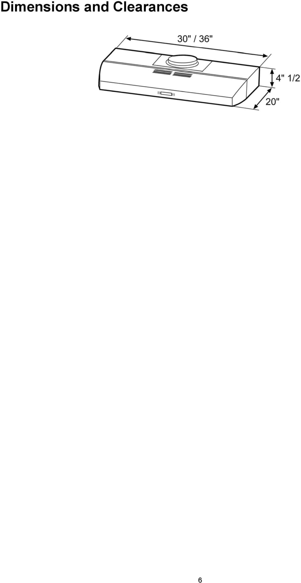
7 Ducting Options and Examples Closely follow the instructions set out in this manual. All responsibility, for any eventual inconveniences, damages or fires caused by not complying with the instructions in this manual, is declined. Venting methods Vent Exhaust Option The hood is designed for vertical or horizontal discharge or can be installed in a recirculating ductless version: Vertical discharge: Use a rectangular duct 3 1/4 x 10 or use a round 7 duct. Horizontal discharge: Use a rectangular duct 3 1/4 x 10 Recirculating (non vented ductless) NOTE: For ductless (Recirculating) version only: purchase the Ductless Recirculating Kit. Minimum Duct Size (Ducting/Ductless version): 7" Round Pipe. Preparation Do not cut a joist or stud unless absolutely necessary. If a joist or stud must be cut, then a supporting frame must be constructed. Fittings material is provided to secure the hood to most types of walls/ceilings. However, a qualified technician must verify suitability of the materials in accordance with the type of wall/ceiling. Before making cutouts, make sure there is proper clearance within the ceiling or wall for exhaust vent. Hood installation height above cooktop is the users preference. The lower the hood is above the cooktop, the more efficient the capturing of cooking odors, grease and smoke. CAUTION: FOR GAS RANGES INSTALLATION: MOUNT THIS HOOD SO THAT THE BOTTOM EDGE IS AT 30" (76,2 CM) ABOVE THE COOKING SURFACE. FOR ELECTRIC RANGES INSTALLATION: MOUNT THIS HOOD SO THAT THE BOTTOM IS NOT LESS THAN 24" (61 CM) AND NOT MORE THAT 30" (76,2 CM) ABOVE THE COOKING SURFACE. HOUSEHOLD USE. PLEASE, READ INSTALLATION MANUAL FOR SPECIFIC APPLICATION. Check your ceiling height and the hood height maximum before you select your hood. 7

8 Installation Installation - Ducting version After having choosen the vent option, proceed as follows: Step 2 Remove the round transition from its seat by unscrewing the its fixing screws (save the screws). Step 5 Remove the duct knockouts using a flat blade screwdriver and a small hammer. Use the screwdriver by knocking out the pannel in similar fashion to a scalpel. Take care of sharp edges. Attention! If it is intended to use the hood in the recirculating version do not remove any duct knockouts and order the necessary charcoal filter from your supplier. R1 = Remove rectangular duct knockout only. R2 = Remove semicircular and rectangular duct knockouts. Step 3 Remove the grease filters. Step 4 Remove the junction box cover. Remove either the top or the back wiring knockout according the preference and install an approved wiring clamp Step 6 For rectangular ducted discharge installations only (otherwise skip to next step) Attach exhaust adaptor/damper over knockout opening with two exhaust adaptor screws. Make sure damper pivot is nearest to top/back edge of hood. Remove tape from damper flap. NOTE: The exhaust adaptor/damper can be installed up to 1 inch on either side of the hood center to accommodate off-center ductwork. In extreme offcenter installations, one end of the duct connector may need to be trimmed to clear the electrical cable clamp. 8

9 Step 7 For round ducted discharge installations only Re-install the round transition with its screws. NOTE: The round transition can be installed up to 1 inch on either side of the hood center to accommodate off-center ductwork. In extreme offcenter installations, one end of the duct connector may need to be trimmed to clear the electrical cable clamp. Outside rear exhaust (Horizontal duct 3 1/4 x 10 Rectangular) Use the diagram or the hood as a template and mark the locations on the cabinet for ductwork, electrical wiring and keyhole screw slots. Step 8 Mark holes Select the vent option that your installation will require and proceed to that section: Outside top exhaust (Vertical duct 3 1/4 x 10 Rectangular) Use the diagram or the hood as a template and mark the locations on the cabinet for ductwork, electrical wiring and keyhole screw slots. Recirculating Use the hood as a template and mark the locations on the cabinet for the electrical wiring and keyhole screw slots. Since the hood is to be recirculated (not to be vented outside), do not cut out any vent openings in the wall or cabinet bottom. Step 9 Choose Venting Option The hood can be set to vent outside or to recirculate air back into the kitchen. The plastic vent lever is located near the center of the hood opening. To vent to the outside, make sure the plastic vent lever is in the HORIZONTAL position (flat against the metal top of the hood). To recirculate air into the kitchen, make sure the plastic vent lever is in the VERTICAL position (flat against the plastic blower housing). Outside top exhaust (Vertical duct 7 Round) Use the diagram or the hood as a template and mark the locations on the cabinet for ductwork, electrical wiring and keyhole screw slots. NOTE: In order to change the vent lever position, you will need to pull the lever out slightly to clear the plastic tabs. 9
 Use the diagram or the hood as a template and mark the locations on the cabinet for ductwork, electrical wiring and keyhole screw slots.")
10 Step 10 For recessed bottom cabinet only If the cabinets have front, side or back trim, make 2 wood shims the width of the trim and attach them to the cabinet bottom recess on both sides. See previous page for marking locations. Run 3 wires; black, white and green,according to the National Electrical Code and local codes and ordinances, in 1/2" conduit from service panel to junction box. Connect black wire from service panel to black or red in junction box, white to white and green to green-yellow. Close and secure junction box cover. Step 11 Cut holes at marked locations for duct and electrical wiring. For the vertical duct, cut out 3/4 extra toward the front of the cabinet so you can move the duct freely when installing the hood. It may also ease installation by cutting the hole 10 1/ 2 instead of 10. Step 12 Drive a mounting screw (from the hardware packet) partway into each center of the narrow neck of the keyhole slots marked on the cabinet bottom. Step 13 Fix the wiring conduit to the hood. Step 16 Final installation steps Replace filters. Check operation of the hood. If range hood does not operate: Check that the circuit breaker is not tripped or the house fuse blown. Disconnect power supply. Check that wiring is correct. To get the most efficient use from your new range hood, read the Use and Care Information section. Keep your Installation Instructions and Use and Care Guide close to range hood for easy reference. Step 14 Slide the hood back against the wall. Tighten the mounting screws. Be sure the screw heads are in the narrow neck of the keyhole slot. Connect Ductwork to hood. Step 15. Electrical connection WARNING Electrical Shock Hazard Warning: Turn off power circuit at the service panel before wiring this unit. 120 VAC, 15 or 20 Amp circuit required. ELECTRICAL GROUNDING INSTRUCTIONS THIS APPLIANCE IS FITTED WITH AN ELECTRICAL JUNCTION BOX WITH 3 WIRES, ONE OF WHICH (GREEN/YELLOW) SERVES TO GROUND THE APPLIANCE. TO PROTECT YOU AGAINST ELECTRIC SHOCK, THE GREEN AND YELLOW WIRE MUST BE CONNECTED TO THE GROUNDING WIRE IN YOUR HOME ELECTRICAL SYSTEM, AND IT MUST UNDER NO CIRCUMSTANCES BE CUT OR REMOVED. Failure to do so can result in death or electrical shock. Remove the knockout and the Junction box cover and install the conduit connector (culus listed) in junction box. 10

11 Description of the hood & Controls 1. Blower and light controls 2. Halogen lamp housings 3. Grease filter Handle 4. Grease filter 11

12 Controls Use the high suction speed in cases of concentrated kitchen vapours. It is recommended that the cooker hood suction is switched on for 5 minutes prior to cooking and to leave in operation during cooking and for another 15 minutes approximately after terminating cooking. Note: Hood retains last speed setting when aspiration switch is turned off. Description of control panel 1. Light Button Press lamp button to turn ON the light on High Intensity (Lamp state previously OFF). Press lamp button to turn ON the light on Low Intensity (Lamp state previously ON). Press lamp button to turn OFF the light (Lamp state previously ON). 2. Timer Button The default timer setting is 10 minutes, and it can be adjusted between 60 minutes and 1 minute. After pressing the timer button, the control enters to a timer setup mode, and user can adjust the timer countdown time with the + and - buttons within 5 seconds. The timer can be initiated immediately pressing the timer button, after setting the timer duration or pressing the timer button twice (default 10 minutes setting). If no action occurs within 5 seconds, the countdown will start. During the timer setup the + and - buttons are dedicated to the timer and no motor action will occur. Once the timer is initiated, it can be cancelled by pressing the timer button again. 3. Display Shows the hood settings. The display will be lit at low intensity when the hood is not operating. Pressing any key the display will light up at high intensity. The display will be lit at high intensity when the hood is operating. If no key is pressed within a minute the display will return to being lit at low intensity Button. Speed Decrease / OFF This button is used to decrease the fan speed, or turn OFF the fan. The fan will turn OFF if the - button is pressed and the hood was in the first speed. If the fan is at second speed and the - button is pressed, the fan will be set to first speed. If the fan is at third speed and the - key is pressed, the fan will be set to second speed. If the fan is at fourth speed and the - button is pressed, the fan will be set to third speed. If the fan is OFF and the - button is pressed, the control backlight will light up Button. Speed Increase / ON This button is used to increase the fan speed, or turn ON the fan. The fan will turn ON if the + button is pressed and the hood was OFF. If the fan is at first speed and the + button is pressed, the fan will be set to second speed. If the fan is at second speed and the + button is pressed, the fan will be set to third speed. If the fan is at third speed and the + button is pressed, the fan will be set to fourth speed. If the fan is at fourth speed and the + button is pressed, a beep will sound. Clock programming The clock can be reprogrammed at any time except during an active timed function. The clock can be displayed in a twelve hour format and valid clock times are from 1:00 to 12:59. The clock can be reprogrammed pressing the Timer button for 3 seconds, and after, the clock can be adjusted with the + and - buttons. The user can have minute increments / decrements of 1 minute, but if the user keep pressing the + / - buttons for more than 1 second, the increments / decrements will be of 5 minutes. During this option the control will round to the nearest 5 minutes. The user can finish on reprogramming the clock pressing the Timer button. After 1 minute of no button pressed the control will accept the programmed clock time and will add one minute to the set clock. Grease filter saturation alarm (Optional) After thirty fan functional hours, the display will show Grease Filter if the fan is active. When this icon is shown in the display, the grease filters installed are required to be washed. To reset the grease filter saturation alarm the user must press the + button for 5 seconds, after this action the icon Grease filter is not displayed, and the hood has the normal display operation. Charcoal filter saturation alarm (Optional) After one hundred and twenty functional hours of the fan, the display will show Charcoal Filter if the fan is active. When this icon flashes on display, the charcoal filters installed are required to be replaced or reactivated. To reset the charcoal filter saturation indication the user must press the - button for 5 seconds, after this time the icon Charcoal filter is not displayed and the hood has the normal display operation. Audible signal activation and deactivation The audible signals can be activated or deactivated pressing the Light button for 5 seconds. If the audible signal is activated, a tone must sound and the Snd symbol must appear on the display for 3 seconds. If the audible signal is deactivated, the Snd symbol must appear on the display for 3 seconds and no tone must sound. 12
. Press lamp button to turn ON the light on Low Intensity (Lamp state previously ON).")
13 Charcoal filter inclusion and exclusion (Recirculating accessories) The charcoal filter inclusion or exclusion can be set by pressing the + and - buttons at the same time for 5 seconds. The Inclusion or exclusion of charcoal filter must be selected while the lamps and the motor are OFF. When the charcoal filter has been excluded, the charcoal filter alarm is disabled. Heat sensor The control is equipped with a heat sensor that will turn on the blower at third speed if excessive heat occurs (over 149 F or 65 C) surrounding the control area. If the blower is OFF or if it is operating at first speed, the blower will be set automatically to third speed, the display shows the word "CArE" to indicate that heat sensor has detected an excessive heat. During this state, the user may raise the blower speed to fourth speed but can not decrease the speed. When the temperature level on the hood drops to normal, the blower will operate in the setting defined by the user before the alarm occured. 13

14 Maintenance ATTENTION! Before performing any maintenance operation, isolate the hood from the electrical supply by switching off at the connector and removing the connector fuse. Or if the appliance has been connected through a plug and socket, then the plug must be removed from the socket. Cleaning Do not spray cleaners directly to the control while cleaning the Hood.The cooker hood should be cleaned regularly (at least with the same frequency with which you carry out maintenance of the fat filters) internally and externally. Clean using the cloth dampened with neutral liquid detergent. Do not use abrasive products. DO NOT USE ALCOHOL! WARNING: Failure to carry out the basic cleaning recommendations of the cooker hood and replacement of the filters may cause fire risks. Therefore, we recommend oserving these instructions. The manufacturer declines all responsibility for any damage to the motor or any fire damage linked to inappropriate maintenance or failure to observe the above safety recommendations. Replacing the light bulb CAUTION Before replacing the lamps, switch power off at service panel and lock service panel disconnecting means to prevent power from being switched on accidentally. NOTE: Turn off the lights and fan. Allow the lights to cool before handling. If new lights do not operate be sure lights are inserted correctly before calling service. Grease Filter Traps cooking grease particles. This must be cleaned once a month using non aggressive detergents, either by hand or in the dishwasher, which must be set to a low temperature and a short cycle. When washed in a dishwasher, the grease filter may discolour slightly, but this does not affect its filtering capacity. To remove the grease filter, pull the spring release handle. Replace Lights Remove the damaged light (twist counter clockwise) and replace with a new 120 Volt, 50 Watt (maximum) 50 halogen light made for a GU10 base, suitable for use in open luminarie. 14

15 Charcoal Filter If the model is not vented to the outside, the air will be recirculated through disposable charcoal filters that help remove smoke and odors. The charcoal filters cannot be cleaned. They must be replaced. The charcoal filters are clipped inside of each metal grease filter (mounting instructions included with charcoal filters kit). The charcoal filters should be replaced every 4-6 months (depending on hood usage). NOTE: DO NOT rinse, or put charcoal filters in an automatic dishwasher. NOTE: Charcoal filters are not included with the hood. They must be ordered from your supplier. Order the needed kit specifying your hood model and width size. Charcoal filter placement (Recirculating accessories) Fit the charcoal filter mattress on the upper side of each grease filter. Use provided springs to fix it in place. Note: When removing for replacing for a new one do not remove Fixing Springs, simply pull out one and rotate outwards. 15

16 Warranty E L I C A N o r t h A m e r ic a TWO YEAR LIMITED WARRANTY TO OBTAIN SERVICE UNDER WARRANTY Owner must present proof of original purchase date. Please keep a copy of your dated proof of purchase (sales slip) in order to obtain service under warranty. PARTS AND SERVICE WARRANTY For the period of two (2) years from the date of the original purchase, Elica will provide free of charge, non consumable parts or components that failed due to manufacturing defects. During this two (2) years limited warranty, Elica will also provide free of charge, all labor and in-home service to replace any defective parts. WHAT IS NOT COVERED Damage or failure to the product caused by accident or act of God, such as, flood, fire or earthquake. Damage or failure caused by modification of the product or use of non-genuine parts. Damage or failure to the product caused during delivery, handling or installation. Damage or failure to the product caused by operator abuse. Damage or failure to the product caused by dwelling fuse replacement or resetting of circuit breakers. Damage or failure caused by use of product in a commercial application. Service trips to dwelling to provide use or installation guidance. Light bulbs, metal or carbon filters and any other consumable part. Normal wear of finish. Wear to finish due to operator abuse, improper maintenance, use of corrosive or abrasive cleaning products/pads and oven cleaner products. WHO IS COVERED This warranty is extended to the original purchaser for products purchased for ordinary residential use in North America (Including the United States, Guam, Puerto Rico, US Virgin Islands & Canada). This warranty is non-transferable and applies only to the original purchaser and does not extend to subsequent owners of the product. This warranty is made expressly in lieu of all other warranties, expressed or implied, including, but not limited to any implied warranty of merchantability or fitness for a particular purpose and all other obligations on the part of Elica North America, provided, however, that if the disclaimer of implied warranties is ineffective under applicable law, the duration of any implied warranty arising by operation of law shall be limited to two (2) years from the date of original purchase at retail or such longer period as may be required by applicable law. This warranty does not cover any special, incidental and/or consequential damages, nor loss of profits, suffered by the original purchaser, its customers and/or the users of the Products. WHO TO CONTACT To obtain Service under Warranty or for any Service Related Question Please Call: Elica North America Authorized Service at (888) Or by Writing To: Elica North America, Attention Customer Service, 222 Merchandise Mart Plaza Suite 947, Chicago, IL USA 16
 years limited warranty, Elica will also provide free of charge, all labor and in-home service to replace any defective parts.")
17 French Sommaire Avis de sécurité important...18 Exigences électriques et exigences d installation...19 Exigences électriques Avant d installer la hotte Liste des pièces...20 Pièces fournies Pièces non fournies Dimensions et Dégagement...21 Exemples et possibilités de positionnement des conduits...22 Méthodes de ventilation Préparation Installation...23 Installation - Version à conduit Description de la hotte et des commandes...27 Commandes Entretien...30 Nettoyage Filtre à graisse Remplacement des ampoules Filtres à charbon Garantie...32 APPROUVÉ POUR LES APPAREILS DE TYPE RÉSIDENTIEL POUR UNE UTILISATION RÉSIDENTIELLE SEULEMENT LISEZ CES INSTRUCTIONS ET CONSERVEZ-LES VEUILLEZ LIRE CES INSTRUCTIONS AU COMPLET AVANT DE COMMENCER. L INSTALLATION DE L APPAREIL DOIT RESPECTER TOUS LES CODES EN VIGUEUR. IMPORTANT : Conservez ces instructions afin de pouvoir les remettre à l inspecteur-électricien de votre région. INSTALLATEUR : Veuillez laisser ces instructions avec l appareil pour le propriétaire. PROPRIÉTAIRE : Veuillez conserver ces instructions pour pouvoir vous y référer plus tard. Avertissement de sécurité : Coupez l alimentation du circuit dans le panneau électrique et verrouillez le panneau avant de raccorder les fils de cet appareil. Exigence : 120 V c.a., 60 Hz circuit de dérivation de 15 V c.a., 20 Hz, de 15 ou 20 A. 17

18 LISEZ CES INSTRUCTIONS ET CONSERVEZ-LES Avis de sécurité important ATTENTION UTILISER CET APPAREIL À DES FINS DE VENTILATION GÉNÉRALE SEULEMENT. NE PAS UTILISER CET APPAREIL POUR ÉVACUER DES MATÉRIAUX OU DES VAPEURS DANGEREUX OU EXPLOSIFS. AVERTISSEMENT POUR RÉDUIRE LES RISQUES D INCENDIE, DE CHOC ÉLECTRIQUE ET DE BLESSURE, RESPECTER LES DIRECTIVES SUIVANTES : A. Utiliser cet appareil uniquement aux fins prévues par le fabricant. Si vous avez des questions à propos de l appareil, communiquez avec le fabricant. B. Avant de faire l entretien de l appareil ou de le nettoyer, coupez l alimentation dans le panneau électrique et verrouillez le panneau en bloquant le dispositif permettant d empêcher d activer l alimentation accidentellement. S il n est pas possible de verrouiller l accès au panneau, fixez une étiquette très voyante au panneau électrique. C. Une personne qualifiée doit effectuer l installation et le câblage des fils électriques en conformité avec tous les codes et toutes les normes, y compris la cote de résistance au feu. D. Il est important de prévoir suffisamment d air pour assurer une bonne combustion de l équipement de chauffe et l évacuation adéquates des gaz par le conduit de cheminé afin de prévenir les refoulements d air. Respectez les directives et les normes de sécurité des fabricants de l équipement de chauffage, comme celles publiées par la National Fire Protection Association (NFPA), la American Society for Heating, Refrigeration and Air Conditioning Engineers (ASHRAE) et le code des autorités de votre région. E. Au moment de couper ou de percer un mur ou un plafond, assurez-vous de ne pas endommager la filerie électrique ou tout autre accès à un service publique. F. Il faut toujours évacuer à l extérieur les systèmes à conduit. ATTENTION Pour réduire les risques d incendie et évacuer l air correctement, assurez-vous que le conduit mène à l extérieur; il ne faut pas évacuer l air dans l espace entre les murs, dans les plafonds, dans les greniers, les vides sanitaires ou les garages. AVERTISSEMENT POUR RÉDUIRE DES RISQUES D INCENDIE, UTILISEZ UNIQUEMENT DES CONDUITS EN MÉTAL. Installez cette hotte en respectant toutes les exigences mentionnées. lorsqu elle est réglée à une haute température. Les débordements par bouillonnement causent de la fumée et des débordements de gras qui peuvent s enflammer. Faites chauffer l huile lentement, à une température basse ou moyenne. b) Faites toujours fonctionner la hotte lorsque vous utilisez la cuisinière à une haute température ou que vous faites flamber des aliments (P. ex. : crêpes Suzette, cerises jubilées, bœuf au poivre flambé). c) Nettoyez les hélices de ventilation fréquemment. Il ne faut pas que la graisse s accumule sur les filres ou les hélices. d) Utilisez le bon format de casserole. Utilisez toujours un chaudron de taille approprié à l élément de la cuisinière. AVERTISSEMENT POUR ÉVITER DE BLESSER QUELQU UN LORS D UN INCENDIE DE GRAISSE SUR LA CUISINIÈRE, SUIVRE LES CONSEILS SUIVANTS : a) ÉTOUFFER LES FLAMMES avec un couvercle aux dimensions de la taque de cuisson, une tôle à biscuit ou tout autre plateau métallique, puis couper le gaz ou l alimentation électrique de la cuisinière. FAIRE ATTENTION A NE PAS SE BRÛLER. Si les flammes ne s éteignent pas immédiatement, QUITTER LA PIÈCE ET APPELER LES POMPIERS. b) NE JAMAIS PRENDRE EN MAIN UNE CASSEROLE EN FEU, vous pourriez vous blesser. c) NE PAS UTILISER D EAU, y compris les essuies de vaisselle ou les serviettes humides une violente explosion due à la vapeur formée pourrait survenir. d) Utiliser un extincteur SEULEMENT si: 1) Vous êtes sûr d avoir un extincteur de classe ABC que vous savez utiliser. 2) Le feu est petit et confiné à la zone où il s est formé. 3) Les pompiers ont été appelés. 4) Vous pouvez lutter contre le feu avec une sortie derrière vous. MODE OPéRATOIRE a. Toujours laisser les grilles de sécurité et les filtres à leur place. Sans la présence de ces derniers, les parties aspirantes pourraient attirer les cheveux, les doigts ou les vêtements. Le fabricant décline toute responsabilité si les informations détaillées dans ce manuel pour l installation, l entretien et l utilisation adéquate du produit ne sont pas observées. Le fabriquant décline en outre toute responsabilité pour d éventuelles blessures dues à des négligences; en outre, la garantie de l appareil sera annulée suite à des conditions d entretien inappropriées. Cet appareil est fabriqué pour un usage interne. Ne pas utiliser cet appareil à l extérieur. AVERTISSEMENT Pour réduire les risques d incendie et de choc électrique, n utilisez pas cette hotte avec un contrôleur de vitesse à semi-conducteurs. AVERTISSEMENT POUR RÉDUIRE LES RISQUES D INCENDIE DE GRAISSE SUR LES CUISINIÈRES. a) Ne laissez jamais la cuisinière sans surveillance 18 ATTENTION Appareil commandé automatiquement - afin de réduire les risques de blessure, débranchez l'appareil de l'alimentation électrique avant de procéder à une réparation. L'appareil est équipé d'un sectionneur intégral situé à l'intérieur du logement du ventilateur.

19 Exigences électriques et exigences d installation Exigences électriques IMPORTANT Respectez tous les codes et les ordonnances en vigueur. Le client a la responsabilité de : Contacter un électricien-installateur. Vérifier que l installation électrique est adéquate et conforme avec le Code national de l électricité, ANSI/NFPA 70 (la plus récente édition*), ou les normes C , Code canadien de l électricité, Partie 1 et C22.2 No.0-M91 (La plus récente édition**) de la CSA, ainsi que tous les codes et les ordonnances de votre région. Si le code le permet et que vous utilisez un fil de mise à la terre distinct, il est recommandé de faire vérifier le chemin du fil par un électricien. Ne pas mettre l appareil à la terre sur une conduite de gaz. Consultez un électricien qualifié si vous n êtes pas certain que la hotte est mise à la terre correctement. N installez pas un fusible dans le circuit neutre ou le circuit de mise à la terre. IMPORTANT Conservez ces instructions afin de pouvoir les remettre à l inspecteur-électricien. La hotte doit être câblée uniquement à l aide de fils de cuivre. Il faut raccorder la hotte directement à une boîte à fusible ou à un disjoncteur par l entremise d une canalisation électrique en métal. Le calibre de fil doit être conforme aux exigences du Code national de l électricité, ANSI/NFPA 70 (La plus récente édition*), ou les normes C , Code canadien de l électricité, Partie 1 et C M91 (La plus récente édition**) de la CSA, ainsi que tous les codes et les ordonnances de votre région. Avant d installer la hotte 1. Pour assurer la ventilation la plus efficace possible, installez la conduite en ligne droite ou avec le moins de coudes possibles. ATTENTION : La sortie de la conduite de ventilation doit donner sur l extérieur. 2. Deux personnes sont nécessaires pour effectuer l installation. 3. La hotte comporte des vis et des ancrages pour mur sec adaptés à la plupart des types de surface; consultez un installateur qualifié pour vous assurer que la quincaillerie fournie est adaptée à votre type de mur ou d armoire. 4. N utilisez pas de conduit flexible. 5. Dans le cas des endroits sujets aux TEMPÉRATURES FROIDES, il faut installer un clapet de contre-tirage supplémentaire afin de minimiser le retour d air froid et un isolant thermique non métallique afin de minimiser la conduction de la température extérieur dans le conduit. Il faut placer le clapet du côté de l air froid de l isolant thermique. L isolant doit être placé le plus près possible de l endroit où le conduit entre dans la partie chauffée de la maison. 6. Air d appoint : Le code du bâtiment de votre région peut exiger l utilisation d un système d air d appoint si vous utilisez un système de ventilation à conduit dont le mouvement d air dépasse un certain nombre de CFM. Le nombre de pi3/min varie d une région à l autre. Consultez un professionnel de CVC pour connaître les exigences précises de votre région. Il faut prévoir un connecteur de canalisation approuvé par l UL ou la CSA à chaque extrémité de la canalisation d alimentation (À la hotte et à la boîte de jonction). Vous pouvez obtenir un exemplaire des normes indiquées en vous adressant à : * La National Fire Protection Association, Batterymarch Park Quincy, Massachusetts, ** La CSA International, 8501 East Pleasant Valley Road, Cleveland, Ohio,
 de la CSA, ainsi que tous les codes et les ordonnances de votre région.")
20 Liste des pièces Pièces fournies Le corps de la hotte assemblé et le raccord métallique circulaire en place. Un raccord métallique rectangulaire avec soupape de tirage Manuel d entretien et utilisation/ Manuel d installation 2 filtres Vis de montage. Pièces non fournies Conduit, canalisation et tous les outils nécessaires à l installation. Trousse de conversion en hotte à recyclage à utiliser seulement avec la version sans conduit (À recyclage) comprend : filtre au charbon 20
 comprend :")
21 Dimensions et Dégagement 21
22 Exemples et possibilités de positionnement des conduits Suivez à la lettre les directives présentées dans ce manuel. Le fabricant refuse toute responsabilité en ce qui a trait à tout préjudice, dommage ou incendie causé par la non observation des directives contenues dans le présent manuel. Méthodes de ventilation Possibilité d évacuation La hotte est prévue pour une évacuation verticale ou horizontale ou bien pour le recyclage d air en l absence de conduits : Évacuation verticale: Utiliser un conduit rectangulaire de 3 ¼»x10" ou utiliser un conduit circulaire de 7". Évacuation horizontale : Utiliser un conduit rectangulaire de 3 ¼»x10" Recyclage d air (pas de conduit nécessaire). NOTE : dans le cas de la version sans conduit (À recyclage) seulement : procurez-vous la trousse de conversion en hotte à recyclage. Diamètre minimum des conduit (Version avec ou sans conduit) : tuyau rond de 7 po. Préparation Ne coupez pas une solive ou un montant à moins qu il soit absolument nécessaire de le faire. Si vous devez couper une solive ou un montant, vous devez construire un cadre de soutien. La quincaillerie fournie permet de fixer la hotte à la plupart des murs et des plafonds. Vous devez cependant demander à un technicien qualifié de vérifier la solidité des matériaux selon le type de mur ou de plafond. Avant de couper, assurez-vous qu il y a un dégagement suffisant dans le plafond ou le mur pour passer la conduite de sortie. Vous pouvez déterminer vous-même la hauteur à laquelle vous installez la hotte au dessus de la cuisinière. Plus la hotte est près de la cuisinière, plus elle est efficace à capter les odeurs de cuisson, la graisse et la fumée. ATTENTION: POUR L INSTALLATION DES CUISINIERES A GAZ: MONTER LA HOTTE AFIN D'AVOIR ENTRE LE BORD INFERIEUR DE LA HOTTE E LE PLAN DE CUISSON UNE DISTANCE DE 30" (76,2 CM). POUR CUISINIERES ELECTRIQUES: MONTER LA HOTTE AFIN D'AVOIR ENTRE LE BORD INFERIEUR DE LA HOTTE ET LE PLAN DE CUISSON LA DISTANCE NE SOIT PAS INFERIEURE DE 24" (61 CM) ET SUPERIEURE DE 30" (76,2 CM). EMPLOI DOMESTIQUE. LIRE ATTENTIVEMENT LE LIVRET INSTRUCTIONS POUR DES APPLICATIONS SPECIFIQUES. Vérifiez donc la hauteur de votre plafond et la hauteur maximum de la hotte avant de choisir votre modèle de hotte. 22
23 Installation Installation - Version à conduit Après avoir choisi le type d évacuation, procéder comme suit: Étape 2 Détacher le raccord circulaire des conduits d évacuation en dévissant les vis qui le fixent (conserver les vis). Étape 5 Enlever les parties prédécoupées pour les conduits en utilisant un fin tournevis et un petit marteau. Utiliser le tournevis à la façon d un biseau. Faire attention aux parties blessants. Attention! En cas d utilisation de la hotte avec recyclage d air, ne pas enlever les parties prédécoupées pour les conduits et commander les filtres à charbon nécessaires chez votre revendeur. Étape 3 Enlever les filtres à graisse. R1 = Enlever uniquement les parties prédécoupées pour les conduits rectangulaires. R2 = Enlever les parties prédécoupées pour les conduits circulaires et rectangulaires. Étape 4 Enlever le couvercle de la boîte de dérivation. Enlever la partie supérieure ou arrière prédécoupée suivant votre préférence et installer une attache électrique homologuée. Étape 6 Pour les évacuations avec conduits rectangulaires uniquement (autrement, passer à l étape suivante) Attacher le joint ou la soupape d évacuation sur l ouverture préformée à l aide des deux vis prévues à cet effet. S assurer que les éléments soient le plus proche possible de la partie arrière en haut de votre hotte. Enlever la protection du clapet. NOTE : Le joint/soupape d évacuation peut être installé jusqu à 2,5 cm (1 inch) de part et d autre du centre de la hotte pour permettre le décentrage des conduits. Dans le cas de systèmes d évacuation très décentrés, la partie terminale du conduit d évacuation peut être modifiée pour dégager l attache du fil électrique. 23
24 Étape 7 Pour les évacuations avec conduits circulaires uniquement Réinstaller le raccord circulaire des conduits d évacuation à l aide des vis. NOTE: Le raccord circulaire peut être installé jusqu à 2,5 cm (1 inch) de part et d autre du centre de la hotte pour permettre le décentrage des conduits. Dans le cas de systèmes d évacuation très décentrés, la partie terminale du conduit d évacuation peut être modifiée pour dégager l attache du fil électrique. Évacuation extérieure par le dessus de la hotte (Conduit vertical circulaire de 7") Utiliser le schéma ou la hotte comme patron et indiquer sur l armoire l emplacement des conduits, des fils électriques et les fentes réglables pour les vis. Étape 8 Emplacement des trous Sélectionner le type d évacuation choisi pour votre hotte et procéder : Évacuation extérieure par le dessus de la hotte (Conduit vertical rectangulaire de 3 1/4 x 10 ) Utiliser le schéma ou la hotte comme patron et indiquer sur l armoire l emplacement des conduits, des fils électriques et les fentes réglables pour les vis. Évacuation extérieure par l arrière de la hotte (Conduit horizontal rectangulaire de 3 1/4 x 10 ) Utiliser le schéma ou la hotte comme patron et indiquer sur l armoire l emplacement des conduits, des fils électriques et les fentes réglables pour les vis. Recyclage d air Utiliser le schéma ou la hotte comme patron et indiquer sur l armoire l emplacement des fils électriques et les fentes réglables pour les vis. Puisque la hotte va recycler l air (il n y a pas d évacuation vers l extérieur), ne pas prévoir d ouverture dans le mur ou l armoire pour le passage des conduits. Étape 9 Sélectionner le type d évacuation choisie pour votre hotte La hotte peut être installée pour évacuer l air à l extérieur ou pour recycler l air dans la cuisine. Le levier de ventilation en plastique est situé près du centre de l ouverture de la hotte. Pour évacuer vers l extérieur, s assurer que le levier de ventilation en plastique est en position HORIZONTALE (à plat contre la partie supérieure métallique de la hotte). Pour recycler l air dans la cuisine, s assurer que le levier de ventilation en plastique est en position VERTICALE (à plat contre la protection en plastique de la soufflerie). 24
25 NOTE : Pour changer la position du levier de ventilation, il est nécessaire de pousser légèrement le levier pour dégager les parties en plastique. Étape 10 Pour armoires encastrées uniquement Si les armoires ont une garniture à l avant, sur le côté ou à l arrière, réaliser 2 morceaux de bois de la largeur des garnitures et les attacher à l armoire encastrée sur les 2 côtés. Pour les emplacements des marques, se référer aux indications à la page précédente. Étape 15. Connexion électrique AVERTISSEMENT Danger de choc électrique AVERTISSEMENT : Coupez l alimentation du circuit dans le panneau électrique avant de raccorder les fils de cet appareil. Un circuit de 120 V c.a., de 15 ou 20 A est requis. INSTRUCTIONS DE MISE À LA TERRE CET APPAREIL EST MUNI D UNE BOÎTE DE JONCTION ÉLECTRIQUE À TROIS FILS, DONT L UN (VERT/JAUNE) SERT À METTRE L APPAREIL À LA TERRE. POUR VOUS PROTÉGER CONTRE LES CHOCS ÉLECTRIQUES, VOUS DEVEZ RACCORDER LE FIL VERT/JAUNE AU FIL DE MISE À LA TERRE DU SYSTÈME ÉLECTRIQUE DE VOTRE MAISON. EN AUCUNE CIRCONSTANCE CE FIL DOIT ÊTRE COUPÉ OU ENLEVÉ. Le fait de ne pas respecter cette directive peut entraîner la mort ou un choc électrique. Retirez l alvéole défonçable et le couvercle de la boîte de jonction et installez un connecteur de canalisation (Listé dans culus) dans la boîte de jonction. Passez trois fils, le noir, le blanc et le vert, en respectant les normes du code national de l électricité, ainsi que les codes et les ordonnances en vigueur dans votre région, dans une canalisation de 1/2 po, du panneau de service à la boîte de jonction. Raccordez le fil noir du panneau de service au fil noir ou rouge de la boîte jonction, le blanc avec le blanc et le vert avec le vert/jaune. Étape 11 Réaliser les trous pour les conduits et les fils électriques aux emplacements indiqués. Pour le conduit vertical, agrandir le trou de 3/4" vers le devant de l armoire pour pouvoir bouger le conduit plus librement lors de la mise en place de la hotte. L installation sera également plus facile si le trou fait 10 ½" au lieu de 10". Fermez le couvercle de la boîte de jonction. Étape 16 Étape finale d installation Replacer les filtres. Vérifier que la hotte fonctionne. Étape 12 Serrer une vis de fixation (se trouvant dans le kit de montage) dans chaque petite ouverture des crochets marqués sur le fond de l armoire. Étape 13 Raccorder le tube électrique à la hotte. Étape 14 Replacer la hotte contre le mur. Serrer les vis de fixation. S assurer que la tête des vis est bien dans la partie plus étroite des fentes des crochets. Raccorder les conduits à la hotte. 25
26 Si la hotte ne fonctionne pas : Vérifiez que le disjoncteur ne s est pas déclenché ou que le fusible n est pas grillé. Débranchez l alimentation. Vérifiez que les raccords électriques ont été effectués correctement. Pour utiliser votre nouvelle hotte de façon optimale, lisez la section intitulée Entretien et utilisation. Gardez vos instructions d installations et d utilisation près de la hotte pour pouvoir vous y référer facilement. 26
27 Description de la hotte et des commandes 1. Boutons de commande du ventilateur et de la lampe 2. Lampe halogène 3. Poignée pour le filtre 4. Filtre à graisse 27
28 Commandes Utiliser la puissance d aspiration maximum en cas de concentration très importante des vapeurs de cuisson. Nous conseillons d allumer le dispositif d aspiration 5 minutes avant de commencer la cuisson et de le faire fonctionner encore pendant 15 minutes environ après avoir terminé la cuisson. Remarque: La hotte enregistre la dernière vitesse lorsque l aspiration est coupée. Description du panneau de commandes 1. Touche Lumière Appuyer sur la touche pour allumer la lumière haute intensité (état précédent lumière OFF). Appuyer sur la touche pour allumer la lumière basse intensité (état précédent lumière ON). Appuyer sur la touche pour éteindre la lumière (état précédent lumière ON). 2. Touche Timer Le réglage par défaut du timer est de 10 minutes et il peut être ajusté entre 60 minutes et 1 minute. Le temps programmé par défaut est de 10 minutes et il peut être ajusté entre 1 minute et 60 minutes. Après avoir appuyé sur la touche Timer, le système entre dans la modalité de réglage et l utilisateur peut régler le temps de compte à rebours du timer en utilisant les touches + et - dans les 5 secondes. Si aucun réglage n est effectué dans les 5 secondes suivant la sélection de la fonction Timer ou le réglage du temps, le compte à rebours commence. Durant le setup du Timer, les touches + et - sont dédiées à la temporisation et ne font pas varier la vitesse du moteur. Une fois le compte à rebours commencé, il peut être annulé en appuyant sur la touche Timer. 3. Display Montre l état de la hotte. Quand la hotte n est pas en fonction, le display s allume à faible intensité. En appuyant sur n importe quelle touche, le display s illumine à forte intensité. Quand la hotte est en fonction, le display s allume à forte intensité. Si aucune touche n est enfoncée pendant 1 minute, le display s illumine de nouveau à faible intensité Touche diminution vitesse / OFF Cette touche est utilisée pour diminuer la vitesse du moteur et pour éteindre la hotte. Le moteur s éteint en appuyant sur la touche - si la hotte se trouve à la première vitesse. Si le moteur se trouve à la deuxième vitesse et si l on appuie sur la touche -, le moteur passe à la première vitesse. Si le moteur se trouve à la troisième vitesse et si l on appuie sur la touche -, le moteur passe à la deuxième vitesse. Si le moteur se trouve à la quatrième vitesse et si l on appuie sur la touche -, le moteur passe à la troisième vitesse. 28 Si le moteur est éteint et que l on appuie sur -, le display s illumine Touche augmentation vitesse / ON Cette touche est utilisée pour augmenter la vitesse du moteur et pour allumer la hotte. Le moteur s allume en appuyant sur la touche + si la hotte se trouve en OFF. Si le moteur se trouve à la première vitesse et si l on appuie sur la touche +, le moteur passe à la deuxième vitesse. Si le moteur se trouve à la deuxième vitesse et si l on appuie sur la touche +, le moteur passe à la troisième vitesse. Si le moteur se trouve à la troisième vitesse et si l on appuie sur la touche +, le moteur passe à la quatrième vitesse. Si le moteur se trouve à la quatrième vitesse et si l on appuie sur la touche +, un beep est émis. Programmation Horloge L horloge peut être réglée à tout moment à l exception de quand la fonction timer est activée. L horloge peut être visualisée dans le format 12 heures avec un temps de visualisation compris entre 1:00 et 12:59. L horloge peut être réglée en appuyant sur la touche Timer pendant 3 secondes, en agissant successivement sur les touches + et - pour régler l heure. L utilisateur peut augmenter/diminuer l heure par pas d 1 minute, mais si la pression des touches + / - est de plus d une seconde, l augmentation/diminution se fera par 5 minutes. Durant cette opération, le contrôle arrondit aux 5 minutes les plus proches. L utilisateur peut terminer la phase de réglage de l heure en appuyant sur la touche Timer. Après 1 minute sans avoir appuyé sur aucune touche, le contrôle accepte la valeur réglée et ajoute 1 minute à celle-ci et commence à compter. Signal saturation Filtres anti-graisses (En option) Après 40 heures de fonctionnement du moteur, apparaît sur le display l indication Grease Filter si le moteur est allumé. Quand ce signal apparaît sur le display, le filtre installé doit être lavé. Pour remettre à zéro le signal de saturation des filtres, l utilisateur doit appuyer sur la touche + pendant 5 secondes, après quoi, le signal Grease Filter disparaît et le display montre l état de fonctionnement. Signal saturation Filtre au Carbone (En option) Après 120 heures de fonctionnement du moteur, apparaît sur le display l indication Charcoal Filter si le moteur est allumé. Quand ce signal apparaît sur le display, le filtre à charbon installé doit être remplacé ou réactivé. Pour remettre à zéro le signal de saturation des filtres, l utilisateur doit appuyer sur la touche - pendant 5 secondes, après quoi, le signal Charcoal Filter disparaît et le display montre l état de fonctionnement. Activation/Désactivation signal acoustique Les signaux sonores peuvent être activés ou désactivés en appuyant sur la touche Lumière pendant 5 secondes. Si le signal sonore est activé, un son est émis et le symbole Snd doit apparaître sur le display pendant 3 secondes.
ASSEMBLY INSTRUCTIONS DIRECTIVES POUR L'ASSEMBLAGE ombre pendant lamp lampe suspendue à tons dégradés, chocolat
 ASSEMBLY INSTRUCTIONS DIRECTIVES POUR L'ASSEMBLAGE ombre pendant lamp lampe suspendue à tons dégradés, chocolat SKU 2728089 INSTRUCTIONAL MANUAL MANUEL D'INSTRUCTIONS 270/2707 COMPONENT LIST LISTE DES
ASSEMBLY INSTRUCTIONS DIRECTIVES POUR L'ASSEMBLAGE luster chandelier lamp chandelier à trois branches en verre lustré
 ASSEMBLY INSTRUCTIONS DIRECTIVES POUR L'ASSEMBLAGE luster chandelier lamp chandelier à trois branches en verre lustré SKU 2711592 INSTRUCTIONAL MANUAL MANUEL D'INSTRUCTIONS 270/2707 COMPONENT LIST LISTE
Lavatory Faucet. Instruction Manual. Questions? 1-866-661-9606 customerservice@artikaworld.com
 Lavatory Faucet Instruction Manual rev. 19-01-2015 Installation Manual You will need Adjustable Wrench Adjustable Pliers Plumber s Tape Hardware list (included) Allen Key Socket wrench tool Important Follow
Thank you for choosing the Mobile Broadband USB Stick. With your USB Stick, you can access a wireless network at high speed.
 Thank you for choosing the Mobile Broadband USB Stick. With your USB Stick, you can access a wireless network at high speed. Note: This manual describes the appearance of the USB Stick, as well as the
Notice Technique / Technical Manual
 Contrôle d accès Access control Encodeur USB Mifare ENCOD-USB-AI Notice Technique / Technical Manual SOMMAIRE p.2/10 Sommaire Remerciements... 3 Informations et recommandations... 4 Caractéristiques techniques...
Thank you for choosing the Mobile Broadband USB Stick. With your USB Stick, you can access a wireless network at high speed.
 Thank you for choosing the Mobile Broadband USB Stick. With your USB Stick, you can access a wireless network at high speed. Note: This manual describes the appearance of the USB Stick, as well as the
Guide d installation Deco Drain inc. DD200
 Guide d installation Deco Drain inc. DD200 Pour plus informations et pour télécharger les guides d installation en couleur, visitez notre site web. www.decodrain.com Soutien technique : Composez le : 514-946-8901
Paxton. ins-20605. Net2 desktop reader USB
 Paxton ins-20605 Net2 desktop reader USB 1 3 2 4 1 2 Desktop Reader The desktop reader is designed to sit next to the PC. It is used for adding tokens to a Net2 system and also for identifying lost cards.
R.V. Table Mounting Instructions
 PTSS165 ACCESSORY MOUNTING INSTRUCTIONS Use these instructions in conjunction with your main manual to properly assemble your gas grill. Refer to the main manual for safety, operating, cleaning and maintenance
Garage Door Monitor Model 829LM
 Garage Door Monitor Model 829LM To prevent possible SERIOUS INJURY or DEATH from a closing garage door: NEVER permit children to operate or play with door control push buttons or remote control transmitters.
03/2013. Mod: WOKI-60IP/TR. Production code: DTWIC 6000
 03/2013 Mod: WOKI-60IP/TR Production code: DTWIC 6000 ENCASTRABLE INDUCTION DROP IN INDUCTION 11/2011 TECHNICAL FEATURES DOCUMENTATION S.A.V. Notice d utilisation : FX00326-A Guide d intervention : ---
GIGABIT PCI DESKTOP ADAPTER DGE-530T. Quick Installation Guide+ Guide d installation+
 GIGABIT PCI DESKTOP ADAPTER Quick Installation Guide+ Guide d installation+ Check Your Package Contents Quick Installation Guide Gigabit Ethernet PCI Adapter CD with Manual and Drivers DO NOT insert the
Contrôle d'accès Access control. Notice technique / Technical Manual
 p.1/18 Contrôle d'accès Access control INFX V2-AI Notice technique / Technical Manual p.2/18 Sommaire / Contents Remerciements... 3 Informations et recommandations... 4 Caractéristiques techniques... 5
Fabricant. 2 terminals
 Specifications Fabricant Nominal torque (Nm) 65 Minimal torque (Nm) 0,63 Coil resistance - 20 C (ohms) 20 Rated current DC (A) 1 Rotor inertia (kg.m 2 ) 2.10-3 Weight (kg) 7,20 Heat dissipation continuous
Warning: Failure to follow these warnings could result in property damage, or personal injury.
 Western Steel & Tube 1 Storage Locker Extended Storage Locker Storage Cabinet Assembly And Use Instructions Warning: Failure to follow these warnings could result in property damage, or personal injury.
Folio Case User s Guide
 Fujitsu America, Inc. Folio Case User s Guide I N S T R U C T I O N S This Folio Case is a stylish, lightweight case for protecting your Tablet PC. Elastic Strap Pen Holder Card Holders/ Easel Stops Figure
Package Contents. System Requirements. Before You Begin
 Package Contents DWA-125 Wireless 150 USB Adapter CD-ROM (contains software, drivers, and manual) Cradle If any of the above items are missing, please contact your reseller. System Requirements A computer
Instructions Mozilla Thunderbird Page 1
 Instructions Mozilla Thunderbird Page 1 Instructions Mozilla Thunderbird Ce manuel est écrit pour les utilisateurs qui font déjà configurer un compte de courrier électronique dans Mozilla Thunderbird et
Guide d'installation rapide TFM-560X YO.13
 Guide d'installation rapide TFM-560X YO.13 Table of Contents Français 1 1. Avant de commencer 1 2. Procéder à l'installation 2 Troubleshooting 6 Version 06.08.2011 16. Select Install the software automatically
Le No.1 de l économie d énergie pour patinoires.
 Le No.1 de l économie d énergie pour patinoires. Partner of REALice system Economie d énergie et une meilleure qualité de glace La 2ème génération améliorée du système REALice bien connu, est livré en
Stainless Steel Solar Wall Light
 V 2.9 Stainless Steel Solar Wall Light User Manual Please read and understand all instructions before use.retain this manual for future reference. V 2.9 Stainless Steel Solar Wall Light SPECIFICATIONS
Instructions pour mettre à jour un HFFv2 v1.x.yy v2.0.00
 Instructions pour mettre à jour un HFFv2 v1.x.yy v2.0.00 HFFv2 1. OBJET L accroissement de la taille de code sur la version 2.0.00 a nécessité une évolution du mapping de la flash. La conséquence de ce
How to Login to Career Page
 How to Login to Career Page BASF Canada July 2013 To view this instruction manual in French, please scroll down to page 16 1 Job Postings How to Login/Create your Profile/Sign Up for Job Posting Notifications
TABLE DES MATIERES A OBJET PROCEDURE DE CONNEXION
 1 12 rue Denis Papin 37300 JOUE LES TOURS Tel: 02.47.68.34.00 Fax: 02.47.68.35.48 www.herve consultants.net contacts@herve consultants.net TABLE DES MATIERES A Objet...1 B Les équipements et pré-requis...2
3M HEPA Vacuum 497AJK. User s Guide
 3M HEPA Vacuum 497AJK User s Guide Table of Contents Section Page Safety Instructions...3 Grounding Instructions...5 Specifications...7 To Operate...7 To Replace Filter...8 Parts List...9 Regulatory Statements...9
Contents Windows 8.1... 2
 Workaround: Installation of IRIS Devices on Windows 8 Contents Windows 8.1... 2 English Français Windows 8... 13 English Français Windows 8.1 1. English Before installing an I.R.I.S. Device, we need to
SA-32 / SA-62 INSTRUCTION MANUAL - MANUEL D INSTRUCTIONS
 SA-32 / SA-62 INSTRUCTION MANUAL - MANUEL D INSTRUCTIONS 4 5 6 7 4 5 6 7 1. Telephone Paging Volume Control 1. Contrôle de volume Paging Téléphone 2. Microphone Volume Control 2. Contrôle volume du microphone
POLICY: FREE MILK PROGRAM CODE: CS-4
 POLICY: FREE MILK PROGRAM CODE: CS-4 Origin: Authority: Reference(s): Community Services Department Cafeteria Services and Nutrition Education Division Resolution #86-02-26-15B.1 POLICY STATEMENT All elementary
Sécurité relative aux sièges auto et aux rehausseurs
 Sécurité relative aux sièges auto et aux rehausseurs Safety with Car Seats and Booster Seats Car crashes are the main cause of accidental death and serious injury of children. Correctly using a car or
Logitech Tablet Keyboard for Windows 8, Windows RT and Android 3.0+ Setup Guide Guide d installation
 Logitech Tablet Keyboard for Windows 8, Windows RT and Android 3.0+ Setup Guide Guide d installation English.......................................... 3 Français.........................................
Contrôle d accès Access control MOD-TCPIP-AI. Notice technique / Technical Manual
 Contrôle d accès Access control MOD-TCPIP-AI Notice technique / Technical Manual Notice technique Mod-TCPIP-AI 9 septembre 2008 v.1.0 p.2/16 Sommaire / Contents Sommaire / Contents...2 Remerciements...3
DOCUMENTATION - FRANCAIS... 2
 DOCUMENTATION MODULE SHOPDECORATION MODULE PRESTASHOP CREE PAR PRESTACREA INDEX : DOCUMENTATION - FRANCAIS... 2 INSTALLATION... 2 Installation automatique... 2 Installation manuelle... 2 Résolution des
Support Orders and Support Provisions (Banks and Authorized Foreign Banks) Regulations
 Regulations") CANADA CONSOLIDATION CODIFICATION Support Orders and Support Provisions (Banks and Authorized Foreign Banks) Regulations Règlement sur les ordonnances alimentaires et les dispositions alimentaires (banques
CANADA CONSOLIDATION CODIFICATION Support Orders and Support Provisions (Banks and Authorized Foreign Banks) Regulations Règlement sur les ordonnances alimentaires et les dispositions alimentaires (banques
PARIS ROISSY CHARLES DE GAULLE
 GPS 2 34 1 E 49 0 46 N GPS* 2 56 56 E 49 0 12 N Votre contact / Your contact: et / and: Accueil : Cabines téléphoniques publiques Reception: Public telephone kiosks Navette Shuttle AÉROPORT DE TT CAR TRANSIT
AND / ET USER GUIDE UK HARDWIRED CONTROL PANEL UK GUIDE UTILISATEUR CENTRALE D ALARME FILAIRE F 496572 1
 AND / ET UK USER GUIDE HARDWIRED CONTROL PANEL UK F GUIDE UTILISATEUR CENTRALE D ALARME FILAIRE 496572 1 English UK Operator Controls and Displays On both control panel and remote keypad the LEDs display
Cheque Holding Policy Disclosure (Banks) Regulations. Règlement sur la communication de la politique de retenue de chèques (banques) CONSOLIDATION
 Regulations. Règlement sur la communication de la politique de retenue de chèques (banques) CONSOLIDATION") CANADA CONSOLIDATION CODIFICATION Cheque Holding Policy Disclosure (Banks) Regulations Règlement sur la communication de la politique de retenue de chèques (banques) SOR/2002-39 DORS/2002-39 Current to
CANADA CONSOLIDATION CODIFICATION Cheque Holding Policy Disclosure (Banks) Regulations Règlement sur la communication de la politique de retenue de chèques (banques) SOR/2002-39 DORS/2002-39 Current to
APPENDIX 6 BONUS RING FORMAT
 #4 EN FRANÇAIS CI-DESSOUS Preamble and Justification This motion is being presented to the membership as an alternative format for clubs to use to encourage increased entries, both in areas where the exhibitor
WINTER BOAT STORAGE SYSTEM SYSTÈME DE REMISAGE HIVERNAL POUR BATEAU
 MANUAL / MANUEL VIDEO WINTER BOAT STORAGE SYSTEM SYSTÈME DE REMISAGE HIVERNAL POUR BATEAU ASSEMBLY INSTRUCTIONS GUIDE D ASSEMBLAGE NAVIGLOO 14-18½ ft/pi FISHING BOAT! RUNABOUT! PONTOON BOAT! SAILBOAT (SAILBOAT
FO-FDHB6-1 Central Heat Blower Kit for Onyx, Opel and Delta
 FO-FDHB6-1 Central Heat Blower Kit for Onyx, Opel and Delta The central heat blower kit enables the distribution of heat generated by the fireplace throughout many rooms and different floors using either
SYSTÈME JETS D AIR WISH WISH AIR JETS SYSTEM Système de massage à jets d air pour bains en polymère - Air jet massage system for polymer bathtubs
 SYSTME JETS D AIR WISH WISH AIR JETS SYSTEM Système de massage à jets d air pour bains en polymère - Air jet massage system for polymer bathtubs Manuel d installation - Installation manual 6835, RUE PICARD
Logitech Speaker System Z553 Setup Guide Guide d installation
 Logitech Speaker System Z553 Setup Guide Guide d installation Logitech Speaker System Z553 English................. 3 Français................ 10 www.logitech.com/support...19 2 Package contents Logitech
ARP-090G / ARP-090K NOTICE D'EMPLOI INSTRUCTION MANUAL
 2 7 NOTICE D'EMPLOI INSTRUCTION MANUAL ARP-090G / ARP-090K Lire attentivement la notice avant d utiliser l appareil Before operating this product, please read user manual completely FRANCAIS EMPLACEMENT
Table de cuisson hlectrique encastrbe en chramique de 76,2 cm (30 po) 30 (76.2 cm) Electric Built-in Ceramic Cooktop
 30 (76.2 cm) Electric Built-in Ceramic Cooktop") Piece no 3188085 Rev. B Part No. 3188085 Rev. B Table de cuisson hlectrique encastrbe en chramique de 76,2 cm (30 po) IMPORTANT: Lire et conserver ces instructions. IMPORTANT : Installateur : Remet-be
Piece no 3188085 Rev. B Part No. 3188085 Rev. B Table de cuisson hlectrique encastrbe en chramique de 76,2 cm (30 po) IMPORTANT: Lire et conserver ces instructions. IMPORTANT : Installateur : Remet-be
First Nations Assessment Inspection Regulations. Règlement sur l inspection aux fins d évaluation foncière des premières nations CONSOLIDATION
 CANADA CONSOLIDATION CODIFICATION First Nations Assessment Inspection Regulations Règlement sur l inspection aux fins d évaluation foncière des premières nations SOR/2007-242 DORS/2007-242 Current to September
MODE D EMPLOI USER MANUAL
 notice_cd 853:notice 9/01/08 15:08 Page 1 CAFETIÈRE À DOSETTES Coffee pad machine CD 853 GIACOMO MODE D EMPLOI USER MANUAL notice_cd 853:notice 9/01/08 15:08 Page 2 FRANÇAIS WHITE & BROWN vous félicite
PROJET DE LOI. An Act to Amend the Employment Standards Act. Loi modifiant la Loi sur les normes d emploi
 2nd Session, 57th Legislature New Brunswick 60-61 Elizabeth II, 2011-2012 2 e session, 57 e législature Nouveau-Brunswick 60-61 Elizabeth II, 2011-2012 BILL PROJET DE LOI 7 7 An Act to Amend the Employment
accidents and repairs:
 accidents and repairs: putting the pieces together accidents et réparations : réunir le tout nobody can repair your Toyota like Toyota Unfortunately, accidents do happen. And the best way to restore your
WiFi Security Camera Quick Start Guide. Guide de départ rapide Caméra de surveillance Wi-Fi (P5)
") #45 #46 WiFi Security Camera Quick Start Guide Guide de départ rapide Caméra de surveillance Wi-Fi (P5) #47 Start Here 1 Is this you? TECH SUPPORT CTRL ALT DEL 2 If yes, turn to page three 1 3 If not,
#45 #46 WiFi Security Camera Quick Start Guide Guide de départ rapide Caméra de surveillance Wi-Fi (P5) #47 Start Here 1 Is this you? TECH SUPPORT CTRL ALT DEL 2 If yes, turn to page three 1 3 If not,
Mesure chimique. Chemical measurement. Sonde de température Pt 1000 Inox Pt 1000 stainless steel. Ref : 703 262. Français p 1.
 Mesure chimique Chemical measurement Français p 1 English p 3 Sonde de température Pt 1000 Inox Pt 1000 stainless steel Version : 6010 Mesure chimique Sonde de température Pt 1000 Inox 1 Description La
BILL 203 PROJET DE LOI 203
 Bill 203 Private Member's Bill Projet de loi 203 Projet de loi d'un député 4 th Session, 40 th Legislature, Manitoba, 63 Elizabeth II, 2014 4 e session, 40 e législature, Manitoba, 63 Elizabeth II, 2014
WEB page builder and server for SCADA applications usable from a WEB navigator
 Générateur de pages WEB et serveur pour supervision accessible à partir d un navigateur WEB WEB page builder and server for SCADA applications usable from a WEB navigator opyright 2007 IRAI Manual Manuel
Utiliser une WebCam. Micro-ordinateurs, informations, idées, trucs et astuces
 Micro-ordinateurs, informations, idées, trucs et astuces Utiliser une WebCam Auteur : François CHAUSSON Date : 8 février 2008 Référence : utiliser une WebCam.doc Préambule Voici quelques informations utiles
Principe de TrueCrypt. Créer un volume pour TrueCrypt
 Sommaire : Principe de TrueCrypt...1 Créer un volume pour TrueCrypt...1 Premier montage...6 Réglages...8 Save Currently Mounted Volumes as Favorite...8 Settings > Preferences...9 TrueCrypt Traveller pour
MANUEL D INSTRUCTIONS K-STAR ÉLECTRIQUE Chauffe-piscine/spa électrique
 GARANTIE (Valide uniquement pour le propriétaire initial) Le chauffe-piscine/spa K-Star est garanti à l acheteur original pendant un an à partir de la date d achat contre tout défaut de fabrication. Exception
AMENDMENT TO BILL 32 AMENDEMENT AU PROJET DE LOI 32
 THAT the proposed clause 6(1), as set out in Clause 6(1) of the Bill, be replaced with the following: Trustee to respond promptly 6(1) A trustee shall respond to a request as promptly as required in the
PRINCIPE DE HOTTE SPÉCIALE COMPLÈTE TYPE «RHC» COMPLETE «RHC» TYPE SPECIAL HOOD SYSTEM
 38 PRINCIPE DE HOTTE SPÉCIALE COMPLÈTE TYPE «RHC» COMPLETE «RHC» TYPE SPECIAL HOOD SYSTEM Cette hotte est spécialement étudiée pour que l extraction soit parfaitement réalisée grâce aux filtres à chocs
Credit Note and Debit Note Information (GST/ HST) Regulations
 Regulations") CANADA CONSOLIDATION CODIFICATION Credit Note and Debit Note Information (GST/ HST) Regulations Règlement sur les renseignements à inclure dans les notes de crédit et les notes de débit (TPS/ TVH) SOR/91-44
CANADA CONSOLIDATION CODIFICATION Credit Note and Debit Note Information (GST/ HST) Regulations Règlement sur les renseignements à inclure dans les notes de crédit et les notes de débit (TPS/ TVH) SOR/91-44
Règlement sur le télémarketing et les centres d'appel. Call Centres Telemarketing Sales Regulation
 THE CONSUMER PROTECTION ACT (C.C.S.M. c. C200) Call Centres Telemarketing Sales Regulation LOI SUR LA PROTECTION DU CONSOMMATEUR (c. C200 de la C.P.L.M.) Règlement sur le télémarketing et les centres d'appel
RULE 5 - SERVICE OF DOCUMENTS RÈGLE 5 SIGNIFICATION DE DOCUMENTS. Rule 5 / Règle 5
 RULE 5 - SERVICE OF DOCUMENTS General Rules for Manner of Service Notices of Application and Other Documents 5.01 (1) A notice of application or other document may be served personally, or by an alternative
Export Permit (Steel Monitoring) Regulations. Règlement sur les licences d exportation (surveillance de l acier) CONSOLIDATION CODIFICATION
 Regulations. Règlement sur les licences d exportation (surveillance de l acier) CONSOLIDATION CODIFICATION") CANADA CONSOLIDATION CODIFICATION Export Permit (Steel Monitoring) Regulations Règlement sur les licences d exportation (surveillance de l acier) SOR/87-321 DORS/87-321 Current to August 4, 2015 À jour
CANADA CONSOLIDATION CODIFICATION Export Permit (Steel Monitoring) Regulations Règlement sur les licences d exportation (surveillance de l acier) SOR/87-321 DORS/87-321 Current to August 4, 2015 À jour
Free filter reminders! Sign up online at: santevia.com/filterease. need help? Contact Santevia! 1-866-943-9220 help@santevia.com.
 Free filter reminders! Sign up online at: need help? Contact Santevia! -866-9-90 help@santevia.com Shower Filter English about our santevia Shower Filter Prevent leaks This shower filter employs NMC leading
RÈGLEMENT SUR LES CEINTURES DE SÉCURITÉ ET LES ENSEMBLES DE RETENUE POUR ENFANTS R.R.T.N.-O. 1990, ch. M-35
 MOTOR VEHICLES ACT SEAT BELT ASSEMBLY AND CHILD RESTRAINT SYSTEM REGULATIONS R.R.N.W.T. 1990,c.M-35 LOI SUR LES VÉHICULES AUTOMOBILES RÈGLEMENT SUR LES CEINTURES DE SÉCURITÉ ET LES ENSEMBLES DE RETENUE
that the child(ren) was/were in need of protection under Part III of the Child and Family Services Act, and the court made an order on
 was/were in need of protection under Part III of the Child and Family Services Act, and the court made an order on") ONTARIO Court File Number at (Name of court) Court office address Applicant(s) (In most cases, the applicant will be a children s aid society.) Full legal name & address for service street & number, municipality,
ONTARIO Court File Number at (Name of court) Court office address Applicant(s) (In most cases, the applicant will be a children s aid society.) Full legal name & address for service street & number, municipality,
Once the installation is complete, you can delete the temporary Zip files..
 Sommaire Installation... 2 After the download... 2 From a CD... 2 Access codes... 2 DirectX Compatibility... 2 Using the program... 2 Structure... 4 Lier une structure à une autre... 4 Personnaliser une
Application Form/ Formulaire de demande
 Application Form/ Formulaire de demande Ecosystem Approaches to Health: Summer Workshop and Field school Approches écosystémiques de la santé: Atelier intensif et stage d été Please submit your application
LOGICIEL D'ADMINISTRATION POUR E4000 & G4000 MANAGEMENT SOFTWARE FOR E4000 & G4000
 LOGICIEL D'ADMINISTRATION POUR E4000 & G4000 MANAGEMENT SOFTWARE FOR E4000 & G4000 TABLE DES MATIÈRES TITRE PAGE Présentation - - - - - - - - - - - - - - - - - - - - - - - - - - - - - - - - - - - -4 Le
Compléter le formulaire «Demande de participation» et l envoyer aux bureaux de SGC* à l adresse suivante :
 FOIRE AUX QUESTIONS COMMENT ADHÉRER? Compléter le formulaire «Demande de participation» et l envoyer aux bureaux de SGC* à l adresse suivante : 275, boul des Braves Bureau 310 Terrebonne (Qc) J6W 3H6 La
Gestion des prestations Volontaire
 Gestion des prestations Volontaire Qu estce que l Income Management (Gestion des prestations)? La gestion des prestations est un moyen de vous aider à gérer votre argent pour couvrir vos nécessités et
GRILLE AU GAZ CB-70M & CB-105M GAS CHAR-BROILER
 GRILLE AU GAZ CB-70M & CB-105M GAS CHAR-BROILER LES INDUSTRIES M.K.E. (1984) INC. M.K.E. INDUSTRIES (1984) INC. 183 boul. Montcalm blvd, Candiac, Qc. J5R 3L6 184 Tel.: (450) 659-6531 / Fax.: (450) 659-2248
User guide Conference phone Konftel 100
 User guide Conference phone Konftel 100 English I Español I Conference phones for every situation Cet emballage contient: 1 x Guide de l utilisateur 1 x Téléphone pour conférences 1 x Transformateur secteur
7 bis impasse Denis Dulac - 94700 Maisons-Alfort FRANCE Tél. : 01 43 68 06 13 / Fax : 01 43 68 66 09 @ : promattex@promattex.com www.promattex.
 7 bis impasse Denis Dulac - 94700 Maisons-Alfort FRANCE Tél. : 01 43 68 06 13 / Fax : 01 43 68 66 09 @ : promattex@promattex.com www.promattex.com NOTICE DB-30 Ce manuel de montage contient les éléments
CALCUL DE LA CONTRIBUTION - FONDS VERT Budget 2008/2009
 Société en commandite Gaz Métro CALCUL DE LA CONTRIBUTION - FONDS VERT Budget 2008/2009 Taux de la contribution au Fonds vert au 1 er janvier 2009 Description Volume Coûts Taux 10³m³ 000 $ /m³ (1) (2)
MANUEL D UTILISATION
 MANUEL D UTILISATION Table des matières Sécurité du produit 3 Mesures de précautions 4 Exigences électriques 5 Dépannage 5 Caractéristiques de My Rotisserie 6 Caractéristiques de My Rotisserie 7 Diagramme
APPENDIX 2. Provisions to be included in the contract between the Provider and the. Holder
 Page 1 APPENDIX 2 Provisions to be included in the contract between the Provider and the Obligations and rights of the Applicant / Holder Holder 1. The Applicant or Licensee acknowledges that it has read
English Q&A #1 Braille Services Requirement PPTC 144918. Q1. Would you like our proposal to be shipped or do you prefer an electronic submission?
 English Q&A #1 Braille Services Requirement PPTC 144918 Q1. Would you like our proposal to be shipped or do you prefer an electronic submission? A1. Passport Canada requests that bidders provide their
SERVEUR DÉDIÉ DOCUMENTATION
 SERVEUR DÉDIÉ DOCUMENTATION Release 5.0.6.0 19 Juillet 2013 Copyright 2013 GIANTS Software GmbH, All Rights Reserved. 1/9 CHANGE LOG Correction de bug divers (5.0.6.0) Ajout d une option de relance automatique
Quick Installation Guide TEW-AO12O
 Quick Installation Guide TEW-AO12O Table of of Contents Contents Français... 1 1. Avant de commencer... 1 2. Installation du matériel... 2 3. Montage... 4 Troubleshooting... 6 Version 10.04.2007 1. Avant
SYSTÈME DE GAINES À SPIRALE ET RACCORDS TOURNANTS
 SYSTÈME DE GAINES À SPIRALE ET RACCORDS TOURNANTS SPIRAL PVC CONDUIT SYSTEMS AND REVOLVING FITTINGS Gaines a Spirale Matufless...page 190 Matufless spiral PVC conduit Raccords Tournants Matufless...page
Ships Elevator Regulations. Règlement sur les ascenseurs de navires CODIFICATION CONSOLIDATION. C.R.C., c. 1482 C.R.C., ch. 1482
 CANADA CONSOLIDATION CODIFICATION Ships Elevator Regulations Règlement sur les ascenseurs de navires C.R.C., c. 1482 C.R.C., ch. 1482 Current to September 10, 2015 À jour au 10 septembre 2015 Last amended
72" STORAGE SHELF OR WORKBENCH ÉTAGERÈ DE RANGEMENT OU ETABLI DE 72 PO
 OPERATING AND SAFETY MANUAL MANUEL D UTILISATION ET DE SÉCURITÉ MODEL MODÈLE: 1TJT004SBH 72" STORAGE SHELF OR WORKBENCH ÉTAGERÈ DE RANGEMENT OU ETABLI DE 72 PO IMPORTANT PLEASE NOTE: WHEN YOU OPEN THE
Software and Hardware Datasheet / Fiche technique du logiciel et du matériel
 Software and Hardware Datasheet / Fiche technique du logiciel et du matériel 1 System requirements Windows Windows 98, ME, 2000, XP, Vista 32/64, Seven 1 Ghz CPU 512 MB RAM 150 MB free disk space 1 CD
An Act to Amend the Tobacco Sales Act. Loi modifiant la Loi sur les ventes de tabac CHAPTER 46 CHAPITRE 46
 2015 CHAPTER 46 CHAPITRE 46 An Act to Amend the Tobacco Sales Act Loi modifiant la Loi sur les ventes de tabac Assented to June 5, 2015 Sanctionnée le 5 juin 2015 Her Majesty, by and with the advice and
LG Electronics, Inc. Display Limited Warranty - USA
 LG Electronics, Inc. Display Limited Warranty - USA Your LG Display will be repaired or replaced in accordance with the terms of this warranty, at LGE s option, if it proves to be defective in material
FCM 2015 ANNUAL CONFERENCE AND TRADE SHOW Terms and Conditions for Delegates and Companions Shaw Convention Centre, Edmonton, AB June 5 8, 2015
 FCM 2015 ANNUAL CONFERENCE AND TRADE SHOW Terms and Conditions for Delegates and Companions Shaw Convention Centre, Edmonton, AB June 5 8, 2015 Early-bird registration Early-bird registration ends April
Critères à l attention des fabricants et des fournisseurs de biens ou de services : dispositifs mécaniques pour bingo
 Alcohol and Gaming Commission des alcools Commission of Ontario et des jeux de l'ontario Gaming Registration & Lotteries Inscription pour les jeux et loteries 90 Sheppard Avenue East 90, avenue Sheppard
USB 598. Quick Start Guide (Windows) Guide de démarrage rapide (Windows) USB Modem. Modem USB. www.sierrawireless.com
 Guide de démarrage rapide (Windows) USB Modem. Modem USB. www.sierrawireless.com") USB 598 With Avec USB Modem Quick Start Guide (Windows) Modem USB Guide de démarrage rapide (Windows) www.sierrawireless.com This guide provides installation instructions for users of: Windows Vista Windows
USB 598 With Avec USB Modem Quick Start Guide (Windows) Modem USB Guide de démarrage rapide (Windows) www.sierrawireless.com This guide provides installation instructions for users of: Windows Vista Windows
Panneau d alimentation de Store Cellulaire
 Panneau d alimentation de Store Cellulaire Directives d installation CSPS-P1-10-6 CSPS-P1-10-6 Entrée : 120-240 V 50/60 Hz 1.5 A Sortie : 12 V 5 A Poids : 3,85 kg (8.5 lb) Répertorié culus (E135084) Directives
Stérilisation / Sterilization
 CONTENEURS Ecoster ecoster CONTAINERS Stérilisation / Sterilization Les conteneurs Ecoster aluminium sont prévus pour contenir des instruments et/ou des tissus pendant toute la durée de la stérilisation
3615 SELFIE. http://graffitiresearchlab.fr HOW-TO / GUIDE D'UTILISATION
 3615 SELFIE http://graffitiresearchlab.fr HOW-TO / GUIDE D'UTILISATION Hardware : Minitel Computer DIN FM545 45 connector (http://www.gotronic.fr/art-fiche-din-fm545-4747.htm) Cable Arduino compatible
Practice Direction. Class Proceedings
 Effective Date: 2010/07/01 Number: PD - 5 Title: Practice Direction Class Proceedings Summary: This Practice Direction describes the procedure for requesting the assignment of a judge in a proceeding under
The new consumables catalogue from Medisoft is now updated. Please discover this full overview of all our consumables available to you.
 General information 120426_CCD_EN_FR Dear Partner, The new consumables catalogue from Medisoft is now updated. Please discover this full overview of all our consumables available to you. To assist navigation
calls.paris-neuroscience.fr Tutoriel pour Candidatures en ligne *** Online Applications Tutorial
 calls.paris-neuroscience.fr Tutoriel pour Candidatures en ligne Online Applications Tutorial 1/4 Pour postuler aux Appels d Offres de l ENP, vous devez aller sur la plateforme : calls.parisneuroscience.fr.
Curve. Innover pour simplifier! Mistral signe les fontaines High Tech à hauteur adaptable. Mistral signs the High Tech coolers with adaptable height
 Innover pour simplifier! Ligne Professionnelle Professional Line Fontaines Réseau Drinking fountains Curve Mistral signe les fontaines High Tech à hauteur adaptable Mistral signs the High Tech coolers
Fontaine à eau. Manuel d utilisation Modèle : X-16 lg-x52 A. Type de distributeur d eau chaude et froide. Compresseur avec réfrigération.
 Fontaine à eau Manuel d utilisation Modèle : X-16 lg-x52 A Type de distributeur d eau chaude et froide. Compresseur avec réfrigération. Nous vous remercions d avoir acheté notre distributeur d eau. Lisez
Interest Rate for Customs Purposes Regulations. Règlement sur le taux d intérêt aux fins des douanes CONSOLIDATION CODIFICATION
 CANADA CONSOLIDATION CODIFICATION Interest Rate for Customs Purposes Regulations Règlement sur le taux d intérêt aux fins des douanes SOR/86-1121 DORS/86-1121 Current to August 4, 2015 À jour au 4 août
Using a Walker. 2. Move your injured or weak leg toward the walker first. If you have had surgery on both legs, use either leg to begin walking.
 Using a Walker Walking with a Walker 1. Lift the walker and place it at a comfortable distance in front of you with all four of its legs on the floor. This distance is often equal to an arm s length. 2.
ETABLISSEMENT D ENSEIGNEMENT OU ORGANISME DE FORMATION / UNIVERSITY OR COLLEGE:
 8. Tripartite internship agreement La présente convention a pour objet de définir les conditions dans lesquelles le stagiaire ci-après nommé sera accueilli dans l entreprise. This contract defines the
Le Cloud Computing est-il l ennemi de la Sécurité?
 Le Cloud Computing est-il l ennemi de la Sécurité? Eric DOMAGE Program manager IDC WE Security products & Solutions Copyright IDC. Reproduction is forbidden unless authorized. All rights reserved. Quelques
Montage- und Gebrauchsanweisung Instructions on mounting and use Prescriptions de montage et mode d'emploi Montage- en gebruiksaanwijzing Istruzioni
 Montage- und Gebrauchsanweisung Instructions on mounting and use Prescriptions de montage et mode d'emploi Montage- en gebruiksaanwijzing Istruzioni di montaggio e d'uso Instrucciones de montaje y para
Savona. Guide d utilisation, d entretien et d installation. www.zephyronline.com ZSA-E30AB, ZSA-M90AB ZSA-E30AS, ZSA-M90AS ZSV-E30AS, ZSV-M90AS
 www.zephyronline.com Guide d utilisation, d entretien et d installation Savona ZSA-E30AB, ZSA-M90AB ZSA-E30AS, ZSA-M90AS ZSV-E30AS, ZSV-M90AS Numéro de modèle : Numéro de série : JUN08.0101 Zephyr Corporation