PURCHASED. IF YOU ARE UNSUCCESSFUL, CALL THE TECHNICAL SUPPORT PHONE NUMBER SHOWN ON THE WATER HEATER LABELING.
|
|
|
- Justin Léonard Papineau
- il y a 8 ans
- Total affichages :
Transcription
1 Instruction Manual RESIDENTIAL GAS WATER HEATERS POWER VENT/POWER DIRECT VENT GAS MODELS WITH HOT SURFACE IGNITION Complies with SCAQMD Low NOx Rule Ashland City, TN CANADIAN MANUAL Thank you for buying this energy efficient water heater. We appreciate your confidence in our products. For Your Safety AN ODORANT IS ADDED TO THE GAS USED BY THIS WATER HEATER. ALL TECHNICAL AND WARRANTY QUESTIONS: SHOULD BE DIRECTED TO THE LOCAL DEALER FROM WHOM THE WATER HEATER WAS PURCHASED. IF YOU ARE UNSUCCESSFUL, CALL THE TECHNICAL SUPPORT PHONE NUMBER SHOWN ON THE WATER HEATER LABELING. Keep this manual in the pocket on heater for future reference whenever maintenance adjustment or service is required. PRINTED

2 table of contents table of contents...2 safe installation, use and service...3 APPROVALS...3 general safety information...4 Precautions...4 Grounding Instructions...4 Hydrogen Gas Flammable...4 introduction...7 Abbreviations Used...7 Qualifications...7 Qualified Installer or Service Agency...7 icomm & BACnet Compatible...7 Preparing For The Installation...7 features and components...8 installation consideration...9 Rough in Dimensions...9 Locating The Water Heater...10 Insulation Blankets Combustion Air and Ventilation Unconfined Space Unusually Tight Construction...12 Confined Space...12 Direct Vent Appliances...12 Exhaust Fans...12 Louvers and Grilles...12 Fresh Air Openings For Confined Spaces...12 Outdoor Air Through Two Openings...12 Outdoor Air Through One Opening...12 Outdoor Air Through Two Horizontal Ducts...13 Air From Other Indoor Spaces...13 Chemical Vapor Corrosion...14 Water Piping...14 Power Supply...14 Power Fluctuations and Electrical Noise...14 Dedicated Power Wiring and Breakers...14 Polarity Sensitive...14 installing the new water heater...14 Mixing Valves...15 Dishwashing Machines...15 Space heating and potable water system...15 Closed Water Systems...15 Thermal Expansion...16 Temperature-Pressure Relief Valve...17 T&P Valve Discharge Pipe Requirements:...17 Gas Piping...18 Condensate Piping...18 High Altitude Installations...19 Sediment Traps (Drip Legs)...19 Filling the Water Heater...19 Venting...20 vent Pipe Termination...20 Planning the Vent System...20 Installation of Vent System...21 Vent Terminal Installation, Sidewall...21 Termination Clearances Sidewall Power Vent...22 Termination Clearances Sidewall Direct Vent...23 Sequence of Installtions, Figure 15A...24 Direct Vent Terminal Installation...24 Installation Sequence...24 Vent Terminals Supplied with Heater Must be Used vent Terminal Installation...25 Flat Roof Installation...25 Concentric Vent Installation...26 Kit Components...26 Safety Considerations...26 Flat Roof Installation...27 direct vent diagram...29 Controls and Switches...30 Blower Prover Switch...30 Blocked Exhaust Switch Blocked Intake Switch...30 On/Off Switch...30 Hot Surface Igniter...30 Power Vent Wiring Schematic - Figure temperature regulation...33 Hi Limit Switch (E.C.O.)...33 control system operation...34 Overview...34 Commercial And Residential Models...34 Control System Navigation...34 User Input Buttons...34 The Desktop Screen...34 Status Icons...35 Operating States...36 Control System Menus...36 User Settings & Control System Menus...37 Temperatures...37 Operating Set Point And Differential Adjustment...37 Temperatures (cont)...38 Heater Status...38 Display Settings...39 Heater Information...39 Current Fault...40 Fault History...40 Fault Occurrence...40 Restore Factory Defaults...40 Service Contact Information...41 for your information...42 Start Up Conditions...42 Smoke/Odor...42 Thermal Expansion...42 Operational Conditions...42 Smelly Water...42 Air in Hot Water Faucets...42 periodic maintenance...43 Venting System Inspection...43 Anode Rod Inspection...43 Temperature-PressureRelief Valve Operation...43 Draining and flushing...44 To drain the water heater storage tank:...44 To flush the water heater storage tank:...44 Service...44 maintenance...45 Temperature-Pressure Relief Valve Test...45 leakage checkpoints...46 troubleshooting...47 Installation Checklist...47 Water Heater Location...47 venting...47 Gas Supply And Piping...47 Condensate Drain...47 Electrical Connections...47 Installation Checklist...47 Sequence Of Operation Flow Chart...48 Operational Problems...49 Rough Starting, Rough Operation...49 Momentary Ignition...49 Not Enough Or No Hot Water...49 Water Is Too Hot...49 Noisy Operation...49 Replacement Parts...49 Fault And Alert Conditions...49 Fault Conditions...49 Alert Conditions...49 Resetting Control System Lock Outs...50 Diagnostic Checks...50 Fault And Alert Messages...51 notes...53 Warranty...55

3 safe installation, use and service The proper installation, use and servicing of this water heater is extremely important to your safety and the safety of others. Many safety-related messages and instructions have been provided in this manual and on your own water heater to warn you and others of a potential injury hazard. Read and obey all safety messages and instructions throughout this manual. It is very important that the meaning of each safety message is understood by you and others who install, use, or service this water heater. This is the safety alert symbol. It is used to alert you to potential personal injury hazards. Obey all safety messages that follow this symbol to avoid possible injury or death. DANGER WARNING CAUTION CAUTION DANGER indicates an imminently hazardous situation which, if not avoided, will result in injury or death. WARNING indicates a potentially hazardous situation which, if not avoided, could result in injury or death. CAUTION indicates a potentially hazardous situation which, if not avoided, could result in minor or moderate injury. CAUTION used without the safety alert symbol indicates a potentially hazardous situation which, if not avoided, could result in property damage. All safety messages will generally tell you about the type of hazard, what can happen if you do not follow the safety message, and how to avoid the risk of injury. APPROVALS 3

4 general safety information Precautions DO NOT USE THIS APPLIANCE IF ANY PART HAS BEEN UNDER WATER. Immediately call a qualified service agency to inspect the appliance and to make a determination on what steps should be taken next. If the unit is exposed to the following, do not operate heater until all corrective steps have been made by a qualified service agency. 1. External fire. 2. Damage. 3. Firing without water. GROUNDING INSTRUCTIONS This water heater must be grounded in accordance with the National Electrical Code and/or local codes. These must be followed in all cases. Failure to ground this water heater properly may also cause erratic control system operation. This water heater must be connected to a grounded metal, permanent wiring system; or an equipment grounding conductor must be run with the circuit conductors and connected to the equipment grounding terminal or lead on the water heater. Hydrogen Gas Flammable Explosion Hazard Flammable hydrogen gases may be present. Keep all ignition sources away from faucet when turning on hot water. Hydrogen gas can be produced in a hot water system served by this appliance that has not been used for a long period of time (generally two weeks or more). Hydrogen gas is extremely flammable. To reduce the risk of injury under these conditions, it is recommended that a hot water faucet served by this appliance be opened for several minutes before using any electrical appliance connected to the hot water system. If hydrogen is present there will probably be an unusual sound such as air escaping through the pipe as the water begins to flow. There should be no smoking or open flame near the faucet at the time it is open. Verify the power to the water heater is turned off before performing any service procedures. Read and understand this instruction manual and the safety messages herein before installing, operating or servicing this water heater. Failure to follow these instructions and safety messages could result in death or serious injury. This manual must remain with the water heater. Water temperature over 125 F (52 C) can cause severe burns instantly resulting in severe injury or death. Children, the elderly and the physically or mentally disabled are at highest risk for scald injury. Feel water before bathing or showering. Temperature limiting devices such as mixing valves must be installed when required by codes and to ensure safe temperatures at fixtures. Explosion Hazard Overheated water can cause water tank explosion. Properly sized temperature and pressure relief valve must be installed in the opening provided. CAUTION Improper installation, use and service may result in property damage. Do not operate water heater if flood damaged. Inspect and anode rods regularly, replace if damaged. Install in location with drainage. Fill tank with water before operation. Properly sized thermal expansion tanks are required on all closed water systems. Refer to this manual for installation and service. 4

5 general safety information 5
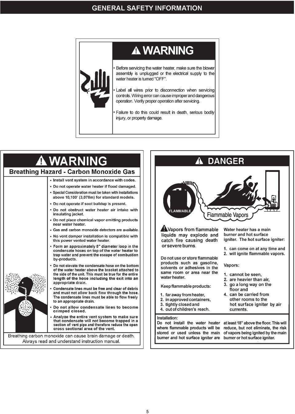
6 General Safety Information Fire or Explosion Hazard Do not store or use gasoline or other flammable vapors and liquids in the vicinity of this or any other appliance. Avoid all ignition sources if you smell gas. Do not expose water heater controls to excessive gas pressure. Use only the gas shown on the water heater rating plate. Maintain required clearances to combustibles. Keep ignition sources away from faucets after extended periods of non-use. Read instruction manual before installing, using or servicing water heater. Breathing Hazard - Carbon Monoxide Gas Do not obstruct water heater air intake with insulating blanket. Gas and carbon monoxide detectors are available. Install water heater in accordance with the instruction manual. Breathing carbon monoxide can cause brain damage or death. Always read and understand instruction manual. CAUTION Property Damage Hazard Fire Hazard For continued protection against risk of fire: Do not install water heater on carpeted floor. Do not operate water heater if flood damaged. Fire and Explosion Hazard Use joint compound or Teflon tape compatible with propane gas. Leak test before placing the water heater in operation. Disconnect gas piping and main gas shutoff valve before leak testing. Install sediment trap in accordance with NFPA 54. Fire and Explosion Hazard Do not use water heater with any gas other than the gas shown on the rating plate. Excessive gas pressure to gas valve can cause serious injury or death. Turn off gas lines during installation. Contact a qualified installer or service agency for installation and service. All water heaters eventually leak. Do not install without adequate drainage. Electrical Shock Hazard Turn off power to the water heater before performing any service. Label all wires prior to disconnecting when performing service. Wiring errors can cause improper and dangerous operation. Verify proper operation after servicing. Failure to follow these instructions can result in personal injury or death. Jumping out control circuits or components can result in property damage, personal injury or death. Service should only be performed by a qualified service agent using proper test equipment. Altering the water heater controls and/or wiring in any way could result in permanent damage to the controls or water heater and is not covered under the limited warranty. Altering the water heater controls and/or wiring in any way could result in altering the ignition sequence allowing gas to flow to the main burner before the hot surface igniter is at ignition temperature causing delayed ignition which can cause a fire or explosion. Any bypass or alteration of the water heater controls and/or wiring will result in voiding the appliance warranty. 6

7 introduction Thank You for purchasing this water heater. Properly installed and maintained, it should give you years of trouble free service. Abbreviations Used Abbreviations found in this Instruction Manual include : ANSI - American National Standards Institute ASME - American Society of Mechanical Engineers GAMA - Gas Appliance Manufacturer s Association NEC - National Electrical Code NFPA - National Fire Protection Association UL - Underwriters Laboratory CSA - Canadian Standards Association Qualifications Qualified Installer or Service Agency Installation and service of this water heater requires ability equivalent to that of a Qualified Agency (as defined by ANSI below) in the field involved. Installation skills such as plumbing, air supply, venting, gas supply and electrical supply are required in addition to electrical testing skills when performing service. ANSI Z Sec : Qualified Agency - Any individual, firm, corporation or company that either in person or through a representative is engaged in and is responsible for (a) the installation, testing or replacement of gas piping or (b) the connection, installation, testing, repair or servicing of appliances and equipment; that is experienced in such work; that is familiar with all precautions required; and that has complied with all the requirements of the authority having jurisdiction. If you are not qualified (as defined by ANSI above) and licensed or certified as required by the authority having jurisdiction to perform a given task do not attempt to perform any of the procedures described in this manual. If you do not understand the instructions given in this manual do not attempt to perform any procedures outlined in this manual. icomm & BACnet Compatible This water heater is compatible with the icomm remote monitoring system. The icomm system hardware and monitoring service is purchased separately. It allows users to monitor critical operational, diagnostic and energy usage data from a secure web site. The icomm system can automatically notify selected personnel via and/or cellular phone text messages if operational problems or user defined Alert Conditions occur. icomm system hardware is compatible with BACnet compliant supervisory controls and building management systems. For more information call Preparing For The Installation 1. Read the entire manual before attempting to install or operate the water heater. Pay close attention to the General Safety Information on page 4 through 6. If you don t follow the safety rules, the water heater may not operate safely. It could cause property damage, injury and/or death. This manual contains instructions for the installation, operation, and maintenance of the water heater. It also contains warnings throughout the manual that you must read and be aware of. All warnings and all instructions are essential to the proper operation of the water heater and your safety. Detailed installation diagrams are also found in this manual. These diagrams will serve to provide the installer with a reference. It is essential that all venting, water piping, gas piping and wiring be installed as shown. The principal components of the water heater are identified in Features And Components on page 8 in this manual. Use this reference to locate and identify various components on the water heater. See the Installation Checklist and Troubleshooting on page 50. By using this checklist the user may be able to make minor operational adjustments and avoid unnecessary service calls. However, service and diagnostic procedures should only be performed by a Qualified Service Agency. Note: Costs to correct installation errors are not covered under the limited warranty. 2. Be sure to turn off power when working on or near the electrical system of the water heater. Never touch electrical components with wet hands or when standing in water. 3. The installation must conform to all instructions contained in this manual and the local code authority having jurisdiction. These shall be carefully followed in all cases. Authorities having jurisdiction should be consulted before installation begins if there are any questions regarding compliance with local, state or national codes. In the absence of local codes, the installation must comply with the current editions of the CAN/CSA-B149.1, Natural Gas and Propane Installation Code and CSA C22.1, the Canadian Electrical Code. All documents are available from the Canadian Standards Association 5060 Spectrum Way, Suite 100, Mississauga, Ontario, Canada L4W 5N6. 4. If after reading this manual you have any questions or do not understand any portion of the instructions, call the toll free number on the back cover of this manual for technical assistance. In order to expedite your request, please have the full Model, Serial and Series number of the water heater you are working with available for the technician. This information is located on the water heater s rating plate. 5. Carefully plan the placement of the water heater. Examine the location to ensure that it complies with the requirements in Locating The Water Heater on page 10 and the Rough In Dimensions on page 9. 7
 in the field involved.")
8 features and components GET TO KNOW YOUR WATER HEATER - GAS MODELS A b c d e f G h I j K l Control Assembly blocked Inlet Switch blocked Outlet Switch blower Prover Switch blower Assembly burner Assembly Flame Sensor hot Surface Igniter Junction Box Gas Control Valve Assembly Display Board top Plastic Enclosure M Display Enclosure ** N Exhaust Elbow Assembly ** O Condensate Tubing p off/on Switch q display Label r Hot Water Outlet t Gas Supply u Main Manual Gas Shutoff Valve v union w Inlet Water Shutoff Valve X Cold Water Inlet Y Inlet Dip Tube Z Temperature and Pressure Relief Valve aa rating Plate bb labels cc drain Valve ** DD Vent Terminal ee drain Pan ff anode GG Insulation hh upper Temperature Probe II Access Door REPLACEMENT PARTS AND DELIMING PRODUCTS Replacement parts and recommended delimer may be ordered through authorized servicers or distributors. When ordering parts, provide complete model and serial numbers (see rating plate), quantity and name of part desired. Standard hardware items may be purchased locally. ACCESS PANEL Caution: This access panel covers a 2 NPT plug that was required during the manufacturing of this water heater. This 2 NPT flange is not a cleanout fitting, removing the 2 NPT plug and using this fitting as a cleanout could void your warranty. VACUUM RELIEF VALVE *INSTALL PER LOCAL CODES * CAUTION HARNESS HAS 120 VAC. IN OPERATION. ** See Planning the Vent System, Installation of Vent System and Condensate Piping for more information. FIGURE 1. 8

9 installation consideration ROUGH IN DIMENSIONS FIGURE 1A. Rough-In-Dimensions Units A B C D E F Inches cm Top/Side Inlet and Outlet: 3/4 NPT Gas Inlet: 1/2 NPT Capacity, Gas and Electrical Characteristics Approximate Capacity Manifold Pressure Electrical Characteristics U.S. Gals. Liters Gas Type WC kpa Volts/Hz Amperes Nat./LP /60 <5 Maximum Supply Pressure: 14 inches W.C. (3.48kPa) Minimum Supply Pressure for Natural Gas: 3.50 (.87kPa) Minimum Supply Pressure for Propane Gas: 8.00 (1.99kPa) Minimum pressure must be maintained under both load and no load (dynamic and static) conditions. Recovery Capacities - U.S. Gallons/Hr. and Liters/Hr. at Temperature Rise Indicated Rating (Btu/hr) Input Rating (kw) 100, Recovery Capacities Temp. F Rise C GPH LPH Recovery capacity based on 96% thermal efficiency 9
 Minimum Supply Pressure for Propane Gas: 8.00 (1.99kPa) Minimum pressure must be maintained under both load and no load (dynamic and static) conditions. Recovery Capacities - U.S. Gallons/Hr.")
10 Locating The Water Heater Carefully choose a location for the new water heater. The placement is a very important consideration for the safety of the occupants in the building and for the most economical use of the appliance. CAUTION Property Damage Hazard All water heaters eventually leak. Do not install without adequate drainage. Whether replacing an existing water heater or installing the water heater in a new location observe the following critical points: 1. The water heater must be located indoors. 2. The water heater must not be located in an area where it will be subject to freezing temperatures. 3. Locate the water heater so it is protected and not subject to physical damage by a moving vehicle. 4. Locate the water heater on a level surface. 5. Locate the water heater near a floor drain. The water heater should be located in an area where leakage of the tank or connections will not result in damage to the area adjacent to the water heater or to lower floors of the structure. When such locations cannot be avoided, it is recommended that a metal drain pan, adequately drained, be installed under the appliance. 6. Locate the water heater close to the point of major hot water usage. 7. Locate the water heater close to a 120 VAC power supply. See Power Supply on page 14 for requirements. 8. Locate the water heater where an adequate supply of fresh air for combustion and ventilation can be obtained. See Combustion Air and Ventilation on page Locate the water heater where the vent and intake air piping, when installed, will remain within the maximum equivalent lengths allowed. See Venting on page Do not locate the water heater where noise (such as the Combustion Blower) during normal operation will be objectionable in adjacent areas. 11. Do not locate the water heater where the subsequent installation of the vent (exhaust) or intake air terminations would be objectionable due to noise at the termination(s). This includes locations close to or across from windows and doors. See Venting starting on page 20. INSTALLATIONS IN AREAS WHERE FLAMMABLE LIQUIDS (VAPORS) ARE LIKELY TO BE PRESENT OR STORED (GARAGES, STORAGE AND UTILITY AREAS, ETC.): Flammable liquids (such as gasoline, solvents, propane (LP or butane, etc.) and other substances (such as adhesives, etc.) emit flammable vapors which can be ignited by a gas water heater s hot surface igniter or main burner. The resulting flashback and fire can cause death or serious burns to anyone in the area. This water heater must not be installed directly on carpeting. Carpeting must be protected by metal or wood panel beneath the appliance extending beyond the full width and depth of the appliance by at least 3 (7.6 cm) in any direction, or if the appliance is installed 10

11 in an alcove or closet, the entire floor must be covered by the panel. Failure to heed this warning may result in a fire hazard. Do not apply insulation to the top of the water heater, as this will interfere with safe operation of the blower assembly. Do not cover the outer door, thermostat or temperature & pressure relief valve. Do not cover the instruction manual. Keep it on the side of the water heater or nearby for future reference. Do obtain new warning and instruction labels from the manufacturer for placement on the blanket directly over the existing labels. COMBUSTION AIR AND VENTILATION Minimum clearances between the water heater and combustible construction are 0 inch at the sides and rear, 5.5 (14.0 cm) from the front and 18 (45.7 cm) from the top. (Standard clearance.) If clearances stated on the heater differ from standard clearances, install water heater according to clearances stated on the heater. A gas water heater cannot operate properly without the correct amount of air for combustion. Do not install in a confined area such as a closet, unless you provide air as shown in the Facts to Consider About Location section. Never obstruct the flow of ventilation air. If you have any doubts or questions at all, call your gas supplier. Failure to provide the proper amount of combustion air can result in a fire or explosion and cause death, serious bodily injury, or property damage. Adequate clearance 30 (76 cm) for servicing this appliance should be considered before installation, such as changing the anodes, control system components and gas control assembly. A minimum clearance of 5.5 (14.0 cm) must be allowed for access to replaceable and/or serviceable parts such as the thermostats, drain valve, condensate drain, relief valve, clean out opening, and the vent connection (exhaust elbow). When installing the heater, consideration must be given to proper location. Location selected should be as close to the wall as practicable and as centralized with the water piping system as possible. INSULATION BLANKETS FIGURE 2. Insulation blankets are available to the general public for external use on gas water heaters but are not necessary with these products. The purpose of an insulation blanket is to reduce the standby heat loss encountered with storage tank heaters. Your water heater meets or exceeds the Energy Policy Act standards with respect to insulation and standby loss requirements, making an insulation blanket unnecessary. Should you choose to apply an insulation blanket to this heater, you should follow these instructions (For identification of components mentioned below, see Figure 1). Failure to follow these instructions can restrict the air flow required for proper combustion, potentially resulting in fire, asphyxiation, serious personal injury or death. FIGURE 3. If this water heater will be used in beauty shops, barber shops, cleaning establishments, or self-service laundries with dry cleaning equipment, it is imperative that the water heater(s) be installed direct vent so that all air for combustion and ventilation is taken from outdoors. Propellants of aerosol sprays and volatile compounds, (cleaners, chlorine based chemicals, refrigerants, etc.) in addition to being highly flammable in many cases, will also react to form corrosive hydrochloric acid when exposed to the combustion products of the water heater. The results can be hazardous, and also cause product failure. 11 Unconfined Space An Unconfined Space is one whose volume is not less than 50 cubic feet per 1,000 Btu/hr (4.8 cubic meters per kw) of the total input rating of all appliances installed in the space. Rooms communicating directly with the space, in which the appliances are installed, through openings not furnished with doors, are considered a part of the unconfined space. Makeup air requirements for the operation of exhaust fans, kitchen

12 ventilation systems, clothes dryers and fireplaces shall also be considered in determining the adequacy of a space to provide combustion, ventilation and dilution air. Outdoor Air Through Two Openings Unusually Tight Construction In unconfined spaces in buildings, infiltration may be adequate to provide air for combustion, ventilation and dilution of flue gases. However, in buildings of unusually tight construction (for example, weather stripping, heavily insulated, caulked, vapor barrier, etc.) additional air must be provided using the methods described in the Confined Space section that follows. Confined Space A Confined Space is one whose volume is less than 50 cubic feet per 1,000 Btu/hr (4.8 cm per kw) of the total input rating of all appliances installed in the space. Openings must be installed to provide fresh air for combustion, ventilation and dilution in confined spaces. The required size for the openings is dependent on the method used to provide fresh air to the confined space and the total Btu/hr input rating of all appliances installed in the space. Direct Vent Appliances Appliances installed in a Direct Vent configuration that derive all air for combustion from the outdoor atmosphere through sealed intake air piping are not factored in the total appliance input Btu/hr calculations used to determine the size of openings providing fresh air into confined spaces. Exhaust Fans Where exhaust fans are installed, additional air shall be provided to replace the exhausted air. When an exhaust fan is installed in the same space with a water heater, sufficient openings to provide fresh air must be provided that accommodate the requirements for all appliances in the room and the exhaust fan. Undersized openings will cause air to be drawn into the room through the water heater s vent system causing poor combustion. Sooting, serious damage to the water heater and the risk of fire or explosion may result. It can also create a risk of asphyxiation. FIGURE 4. The confined space shall be provided with two permanent openings, one commencing within 12 inches (300 mm) of the top and one commencing within 12 inches (300 mm) of the bottom of the enclosure. The openings shall communicate directly with the outdoors. See Figure 4. Each opening shall have a minimum free area of 1 square inch per 4,000 Btu/hr (550 mm 2 per kw) of the aggregate input rating of all appliances installed in the enclosure. Each opening shall not be less than 100 square inches (645 cm 2 ). Outdoor Air Through One Opening Louvers and Grilles The free areas of the fresh air openings in the instructions that follow do not take in to account the presence of louvers, grilles or screens in the openings. The required size of openings for combustion, ventilation and dilution air shall be based on the net free area of each opening. Where the free area through a design of louver or grille or screen is known, it shall be used in calculating the size of opening required to provide the free area specified. Where the louver and grille design and free area are not known, it shall be assumed that wood louvers will have 25% free area and metal louvers and grilles will have 75% free area. Non motorized louvers and grilles shall be fixed in the open position. Fresh Air Openings For Confined Spaces The following instructions shall be used to calculate the size, number and placement of openings providing fresh air for combustion, ventilation and dilution in confined spaces. The illustrations shown in this section of the manual are a reference for the openings that provide fresh air into confined spaces only. Do not refer to these illustrations for the purpose of vent installation. See Venting Installation on page 20 for complete venting installation instructions. FIGURE 5. Alternatively a single permanent opening, commencing within 12 inches (300 mm) of the top of the enclosure, shall be provided. See Figure 5. The water heater shall have clearances of at least 1 inch (25 mm) from the sides and back and 6 inches (l50 mm) from the front of the appliance. The opening shall directly communicate with the outdoors or shall communicate through a vertical or horizontal duct to the outdoors or spaces that freely communicate with the outdoors and shall have a minimum free area of the following: 12
 additional air must be provided using the methods described in the Confined Space section that follows.")
13 1. 1 square inch per 3000 Btu/hr (700 mm 2 per kw) of the total input rating of all appliances located in the enclosure, and Air From Other Indoor Spaces 2. Not less than the sum of the areas of all vent connectors in the space. Outdoor Air Through Two Horizontal Ducts FIGURE 6. The confined space shall be provided with two permanent horizontal ducts, one commencing within 12 inches (300 mm) of the top and one commencing within 12 inches (300 mm) of the bottom of the enclosure. The horizontal ducts shall communicate directly with the outdoors. See Figure 6. Each duct opening shall have a minimum free area of 1 square inch per 2,000 Btu/hr (1100 mm 2 per kw) of the aggregate input rating of all appliances installed in the enclosure. When ducts are used, they shall be of the same cross sectional area as the free area of the openings to which they connect. The minimum dimension of rectangular air ducts shall be not less than 3 inches. FIGURE 7. The confined space shall be provided with two permanent openings, one commencing within 12 inches (300 mm) of the top and one commencing within 12 inches (300 mm) of the bottom of the enclosure. See Figure 7. Each opening shall communicate directly with an additional room(s) of sufficient volume so that the combined volume of all spaces meets the criteria for an Unconfined Space. Each opening shall have a minimum free area of 1 square inch per 1,000 Btu/hr (1100 mm 2 per kw) of the aggregate input rating of all appliances installed in the enclosure. Each opening shall not be less than 100 square inches (645 cm 2 ). 13

14 CHEMICAL VAPOR CORROSION CORROSION OF THE FLUEWAYS AND VENT SYSTEM MAY OCCUR IF AIR FOR COMBUSTION CONTAINS CERTAIN CHEMICAL VAPORS. SUCH CORROSION MAY RESULT IN FAILURE AND RISK OF ASPHYXIATION. installing the new water heater Spray can propellants, cleaning solvents, refrigerator and air conditioning refrigerants, swimming pool chemicals, calcium and sodium chloride (water softener salt), waxes, and process chemicals are typical compounds which are potentially corrosive. Do not store products of this sort near the heater. Also, air which is brought in contact with the heater should not contain any of these chemicals. If necessary, uncontaminated air should be obtained from remote or outside sources. The limited warranty is voided when failure of water heater is due to a corrosive atmosphere. (See limited warranty for complete terms and conditions). Water Piping This water heater shall not be connected to any heating systems or component(s) used with a non-potable water heating appliance. All piping components connected to this unit for space heating applications shall be suitable for use with potable water. Toxic chemicals, such as those used for boiler treatment shall not be introduced into this system. When the system requires water for space heating at temperatures higher than required for domestic water purposes, a mixing valve must be installed. Please refer to Figure 8 for suggested piping arrangement. Power Supply The water heaters covered in this manual require a 120 VAC, 1Ø (single phase), 60Hz, 15 amp power supply and must also be electrically grounded in accordance with local codes or, in the absence of local codes, with the Canadian Electrical Code CSA C22.1. Power Fluctuations and Electrical Noise The water heater s control system requires a source of stable clean electricity for proper operation. Connecting the water heater to a branch circuit that is subject to fluctuations in voltage level or electrical line noise such as EMI (electro magnetic interference) or RFI (radio frequency interference) may cause erratic control system operation and malfunction. HOTTER WATER CAN SCALD: Water heaters are intended to produce hot water. Water heated to a temperature which will satisfy space heating, clothes washing, dish washing, cleaning and other sanitizing needs can scald and permanently injure you upon contact. Some people are more likely to be permanently injured by hot water than others. These include the elderly, children, the physically or developmentally disabled. If anyone using hot water fits into one of these groups or if there is a local code or state law requiring a certain temperature water at the hot water tap, then you must take special precautions. In addition to using the lowest possible temperature setting that satisfies your hot water needs, a means such as a *mixing valve, should be used at the hot water taps used by these people or at the water heater, see Figure 8. Valves for reducing point of use temperature by mixing cold and hot water are also available: Consult a Qualified Installer or Service Agency. Follow manufacturer s instructions for installation of the valves. Before changing the factory setting on the thermostat, read the Temperature Regulation section in this manual. A high quality power supply filter/suppressor such as the Kleen Line model SELF/T-10 Series SC-L or equivalent must be installed if the above conditions exist. Call the technical support phone number listed on the back cover of this manual for more information. Note: Malfunctions caused by the power supply and the costs to install power supply filters are not covered under the limited warranty. Dedicated Power Wiring and Breakers Dedicated power supply wires, ground wiring and dedicated circuit breakers often prevent electrical line noise and should be considered when installing the water heater. Polarity Sensitive The control system on the water heaters covered in this manual is polarity sensitive; electronic flame sensing requires correct polarity. The control system is programmed to monitor the incoming power supply. If the Hot and Neutral wires in the 120 VAC power supply are reversed, the control system will declare a Fault condition and lock out, heating operation will be disabled until the power supply is correctly wired. The control system will display the AC Reversed Fault message on the LCD. 14

15 Mixing Valves Water temperature over 125 F (52 C) can cause severe burns instantly resulting in severe injury or death. Children, the elderly and the physically or mentally disabled are at highest risk for scald injury. Feel water before bathing or showering. Temperature limiting devices such as mixing valves must be installed when required by codes and to ensure safe temperatures at fixtures. in improperly sanitized dishes. Where pressures are high, a water pressure reducing or flow regulating control valve should be used in the line to the dishwashing machine and should be adjusted to deliver water pressure between these limits. COLD WATER INLET TEMPERED WATER OUTLET HOT WATER OUTLET CHECK VALVE TO TANK INLET 12 TO 15 (30-38 cm) MIXING VALVE CHECK VALVE Water heated to a temperature which will satisfy clothes washing, dish washing, and other sanitizing needs can scald and cause permanent injury upon contact. Short repeated heating cycles caused by small hot water uses can cause temperatures at the point of use to exceed the water heater s temperature setting by up to 20 F (11 C). Some people are more likely to be permanently injured by hot water than others. These include the elderly, children, the infirm and the physically/mentally disabled. Table 1 shows the approximate timeto-burn relationship for normal adult skin. If anyone using hot water provided by the water heater being installed fits into one of these groups or if there is a local code or state law requiring a certain water temperature at the point of use, then special precautions must be taken. In addition to using the lowest possible temperature setting that satisfies the demand of the application a Mixing Valve should be installed at the water heater (see Figure 8) or at the hot water taps to further reduce system water temperature. Mixing valves are available at plumbing supply stores. Consult a Qualified Installer or Service Agency. Follow mixing valve manufacturer s instructions for installation of the valves. Table 1 Water Temperature Time to Produce 2nd & 3rd Degree Burns on Adult Skin 160 F (71 C) About 1/2 second 150 F (66 C) About 1-1/2 seconds 140 F (60 C) Less than 5 seconds 130 F (54 C) About 30 seconds 120 F (49 C) More than 5 minutes Dishwashing Machines All dishwashing machines meeting the National Sanitation Foundation requirements are designed to operate with water flow pressures between 15 and 25 pounds per square inch (103 kpa and 173 kpa). Flow pressures above 25 pounds per square inch (173 kpa), or below 15 pounds per square inch (103 kpa), will result Figure 8. Space heating and potable water system Your water heater is equipped with inlet/outlet connections for use in space heating applications (see Figure 9). If this water heater is to be used to supply both space heating and potable (drinking) water, the instructions listed below must be followed: Be sure to follow the manual(s) shipped with the air handler or other type heating system. This water heater is not to be used as a replacement for an existing boiler installation. Do not use with piping that has been treated with chromates, boiler seal or other chemicals and do not add any chemicals to the water heater piping If the space heating system requires water temperatures in excess of 120 F, a mixing valve must be installed per the manufacturer s instructions in the potable hot water supply to limit the risk of scald injury. Pumps, valves, piping and fittings must be compatible with potable water. A properly installed flow control valve is required to prevent thermosiphoning. Thermosiphoning is the result of a continuous flow of water through the air handler circuit during the off cycle. Weeping (blow off) of the temperature and pressure relief valve (T & P) or higher than normal water temperatures are the fi rst signs of thermosiphoning. The hot water line from the water heater should be vertical past any mixing valve or supply line to the heating system to remove air bubbles from the system. Do not connect the water heater to any system or components previously used with non-potable water heating appliances when used to supply potable water. 15

16 Figure 9. CLOSED WATER SYSTEMS Water supply systems may, because of code requirements or such conditions as high line pressure, among others, have installed devices such as pressure reducing valves, check valves, and back flow preventers. Devices such as these cause the water system to be a closed system. THERMAL EXPANSION As water is heated, it expands (thermal expansion). In a closed system the volume of water will grow when it is heated. As the volume of water grows there will be a corresponding increase in water pressure due to thermal expansion. Thermal expansion can cause premature tank failure (leakage). This type of failure is not covered under the limited warranty. Thermal expansion can also cause intermittent temperature-pressure relief valve operation: water discharged from the valve due to excessive pressure build up. This condition is not covered under the limited warranty. The temperature-pressure relief valve is not intended for the constant relief of thermal expansion. Figure 10. NOTE: To protect against untimely corrosion of hot and cold water fittings, it is strongly recommended that di-electric unions or couplings be installed on this water heater when connected to copper pipe, see Figure 10 also. Figures 9 and 10 show the typical attachment of the water piping to the water heater. The water heater is equipped with 3/4 inch NPT water connections. NOTE: If using copper tubing, solder tubing to an adapter before attaching the adapter to the water heater connections. Do not solder the water lines directly to the water heater connections. It will harm the dip tube and damage the tank. T & P Valve and Pipe Insulation (if supplied) Remove insulation for T & P valve and pipe connections from carton. A properly sized thermal expansion tank should be installed on all closed systems to control the harmful effects of thermal expansion. Figure

17 Fit pipe insulation over the incoming cold water line and the hot water line. Make sure that the insulation is against the top cover of the heater.fit T & P valve insulation over valve. Make sure that the insulation does not interfere with the lever of the T & P valve. Secure all insulation using tape. Temperature-Pressure Relief Valve Explosion Hazard Temperature-Pressure Relief Valve must comply with ANSI Z CSA 4.4 and ASME code. Properly sized temperaturepressure relief valve must be installed in opening provided. Can result in overheating and excessive tank pressure. Can cause serious injury or death. This water heater is provided with a properly rated/sized and certified combination Temperature-Pressure Relief Valve (T&P valve) by the manufacturer. The valve is certified by a nationally recognized testing laboratory that maintains periodic inspection of production of listed equipment of materials as meeting the requirements for Relief Valves for Hot Water Supply Systems, ANSI Z21.22 CSA 4.4, and the code requirements of ASME. If replaced, the new T&P valve must meet the requirements of local codes, but not less than a combination Temperature- Pressure Relief Valve rated/sized and certified as indicated in the above paragraph. The new valve must be marked with a maximum set pressure not to exceed the marked hydrostatic working pressure of the water heater (150 psi = 1,035 kpa) and a discharge capacity not less than the water heater Btu/hr or kw input rate as shown on the water heater s model rating plate. No valve or other obstruction is to be placed between the Temperature-Pressure Relief Valve and the tank. Do not connect discharge piping directly to the drain unless a 6 (15.2 cm) air gap is provided. To prevent bodily injury, hazard to life, or property damage, the relief valve must be allowed to discharge water in adequate quantities should circumstances demand. If the discharge pipe is not connected to a drain or other suitable means, the water flow may cause property damage. CAUTION Water Damage Hazard Temperature-Pressure Relief Valve discharge pipe must terminate at adequate drain. T&P Valve Discharge Pipe Requirements: Shall not be smaller in size than the outlet pipe size of the valve, or have any reducing couplings or other restrictions. Shall not be plugged or blocked. Shall not be exposed to freezing temperatures. Shall be of material listed for hot water distribution. Shall be installed so as to allow complete drainage of both the Temperature-Pressure Relief Valve and the discharge pipe. Must terminate a maximum of six inches above a floor drain or external to the building. In cold climates, it is recommended that the discharge pipe be terminated at an adequate drain inside the building. Shall not have any valve or other obstruction between the relief valve and the drain. Burn hazard. Hot water discharge. Keep clear of Temperature- Pressure Relief Valve discharge outlet. Note: In addition to the factory installed Temperature-Pressure Relief Valve on the water heater, each remote storage tank that may be installed and piped to a water heating appliance must also have its own properly sized, rated and approved Temperature-Pressure Relief Valve installed. Call the toll free technical support phone number listed on the back cover of this manual for technical assistance in sizing a Temperature- Pressure Relief Valve for remote storage tanks. For safe operation of the water heater, the Temperature- Pressure Relief Valve must not be removed from its designated opening nor plugged. The Temperature-Pressure Relief Valve must be installed directly into the fitting of the water heater designed for the relief valve. Install discharge piping so that any discharge will exit the pipe within 6 inches (15.2 cm) above an adequate floor drain, or external to the building. In cold climates it is recommended that it be terminated at an adequate drain inside the building. Be certain that no contact is made with any live electrical part. The discharge opening must not be blocked or reduced in size under any circumstances. Excessive length, over 30 feet (9.14 m), or use of more than four elbows can cause restriction and reduce the discharge capacity of the valve. 17 The Temperature-Pressure Relief Valve must be manually operated at least twice a year. Caution should be taken to ensure that (1) no one is in front of or around the outlet of the Temperature-Pressure Relief Valve discharge line, and (2) the water manually discharged will not cause any bodily injury or property damage because the water may be extremely hot. If after manually operating the valve, it fails to completely reset and continues to release water, immediately close the cold water inlet to the water heater, follow the draining instructions in this manual, and replace the Temperature-Pressure Relief Valve with a properly rated/sized new one. Note: The purpose of a Temperature-Pressure Relief Valve is to prevent excessive temperatures and pressures in the storage tank. The T&P valve is not intended for the constant relief of thermal expansion. A properly sized thermal expansion tank must be installed on all closed systems to control thermal expansion, see Closed Water Systems and Thermal Expansion on pages 15 and 16. If you do not understand these instructions or have any questions regarding the Temperature-Pressure Relief Valve call the toll free number listed on the back cover of this manual for technical assistance.

18 gas piping Consideration must be given to avoid freezing of the condensate lines which could result in excessive build up of condensate inside the water heater. Waterproof heat tape may be required to prevent freezing of the condensate lines. Please ensure that the outlet of the condensate drain does not create a slippery condition which could lead to personal injury. Make sure gas supplied is same type listed on model rating plate. The inlet gas pressure must not exceed 14 inch water column (3.5 kpa) for natural and propane gas (L.P.). The minimum inlet gas pressure shown on rating plate is that which will permit firing at rated input. All gas piping must comply with local codes and ordinances or with the National Gas and Propane Installation Code (CAN/CSA-B149.1). Copper or brass tubing and fittings (except tin lined copper tubing) shall not be used. If the gas control valve is subjected to pressures exceeding 1/2 psi (3.5 kpa), the damage to the gas control valve could result in a fire or explosion from leaking gas. If the main gas line Shut-off serving all gas appliances is used, also turn off the gas at each appliance. Leave all gas appliances shut off until the water heater installation is complete. CONDENSATION WARNING: THIS WATER HEATER IS A CONDENSING UNIT AND REQUIRES A DRAIN TO BE LOCATED IN CLOSE PROXIMITY TO ALLOW CONDENSATE TO DRAIN SAFELY. THE CONDENSATE DRAINS FROM UNIT AT THE EXHAUST ELBOW LOCATED AT BOTTOM OF UNIT. NOTE: IT IS IMPORTANT THAT THE CONDENSATE HOSE NOT BE ELEVATED ABOVE THE EXHAUST ELBOW, SEE FIGURE 12. CONDENSATE BUILD-UP WILL BLOCK THE EXHAUST OUTLET, WHICH WILL CAUSE IMPROPER OPERATION. A gas line of sufficient size must be run to the water heater. Consult the current edition of Natural Gas and Propane Installation Code (CAN/CSA-B149.1) and your gas supplier concerning pipe size. There must be: A readily accessible manual shut off valve in the gas supply line serving the water heater, and Figure 12 A sediment trap (drip leg) ahead of the gas control valve to help prevent dirt and foreign materials from entering the gas control valve. A flexible gas connector or a ground joint union between the shut off valve and control valve to permit servicing of the unit. Be sure to check all the gas piping for leaks before lighting the water heater. Use a soapy water solution, not a match or open flame. Rinse off soapy solution and wipe dry. CONDENSATE Piping This water heater is a condensing unit and requires a drain to be located in close proximity to allow the condensate to drain safely. The condensate drains from the unit at the exhaust tee located at the bottom of the unit (see figure 12). Condensate from this water heater is mildly acidic. Please note that some local codes require that condensate is treated by using a ph neutralizing filter prior to disposal. Caution must be used to ensure that the drain is free and clear of debris and will not allow backflow through the condensate hose. 18 The condensate drain line must be routed to a suitable drain. If no floor drain is available or the drain is above the level of the condensate line, install a condensate pump that is resistant to the acidic condensate. These pumps are available from local distributors. If the pump is not resistant to acidic water, a condensate neutralizer must be used ahead of the pump. When installing the drain line, note the following: Plastic pipe or tubing must be used to connect the condensate drain to a suitable drain or condensate pump. Do not use copper tubing, iron, or steel pipe for the condensate drain line. Condensate drain lines should be installed in conditioned areas only. Drain lines installed in areas that are subject to freezing temperatures should be wrapped with a nationally recognized/listed heat tape and/or approved insulation for freeze protection. Install per manufacturer s instructions. Do not common drain with the temperature and pressure relief valve or the condensate line from an air conditioner evaporator coil. Slope the condensate drain toward the inside floor drain or condensate pump. The condensate drain line and connection to the drain piping must comply with all local codes.
 for natural and propane gas (L.P.). The minimum inlet gas pressure shown on rating plate is that which will permit firing at rated input.")
19 HIGH ALTITUDE INSTALLATIONS SEDIMENT TRAPS (drip legs) This high efficiency water heater is certified for use without modification for an altitude of 10,000 feet (3,079 meters). Consult the factory for installation at altitudes over 10,100 feet (3,079m). Some gas utility companies derate their gas for altitude, making it unnecessary to install high altitude orifices. Call the local gas or utility company to verify BTU content. Due to the input ration reduction at high altitudes, the output rating of the appliance is also reduced and should be compensated for in the sizing of the equipment for applications. A sediment trap (drip leg) shall be installed as close to the gas inlet of the water heater as practical at the time of water heater installation. The sediment trap (drip leg) shall be either a tee fitting with a capped nipple in the bottom outlet or other device recognized as an effective sediment trap (drip leg). Contaminants in the gas lines may cause improper operation of the gas control valve that may result in fire or explosion. Before attaching the gas line be sure that all gas pipe is clean on the inside. To trap any dirt or foreign material in the gas supply line, a drip leg (sometimes called a sediment trap) must be incorporated in the piping. The drip leg must be readily accessible. Install in accordance with the Gas Piping section. Refer to the current edition of the Natural Gas and Propane Installation Code (CAN/ CSA-B Filling the Water Heater Use pipe joint compound or teflon tape marked as being resistant to the action of petroleum [Propane (L.P.)] gases. Never use this water heater unless it is completely full of water. To prevent damage to the tank, the tank must be filled with water. Water must flow from the hot water faucet before turning ON gas to the water heater. To fill the water heater with water: The appliance and its gas connection must be leak tested before placing the appliance in operation. The appliance and its individual Shut-off valve shall be disconnected from the gas supply piping system during any pressure testing of that system at test pressures in excess of 1/2 pound per square inch (3.5 kpa). It shall be isolated from the gas supply piping system by closing its individual manual Shut-off valve during any pressure testing of the gas supply piping system at test pressures equal to or less than 1/2 pound per square inch (3.5 kpa). Important: Make sure the gas line is piped in with hard pipe. Avoid flex line construction for gas due to possible gas flow problems Close the water heater drain valve by turning the handle to the right (clockwise). The drain valve is on the lower front of the water heater. 2. Open the cold water supply valve to the water heater. NOTE: The cold water supply valve must be left open when the water heater is in use. 3. To insure complete filling of the tank, allow air to exit by opening the nearest hot water faucet. Allow water to run until a constant flow is obtained. This will let air out of the water heater and the piping. 4. Check all water piping and connections for leaks. Repair as needed.

20 VENTING planned location of the vent terminal. 1. Layout total vent system to use a minimum of vent pipe and elbows. 2. This water heater is capable of venting flue gases equivalent to 45 (13.7 m) of 2 pipe, 128 (39 m) of 3 pipe as listed in Table 2. Table 2 Number of 90 Elbows 2 Maximum Pipe - ft. (m) 3 Maximum Pipe - ft. (m) 1 40 (12.19) 120 (36.57) 2 35 (10.66) 115 (35.05) 3 30 (9.14) 110 (33.52) 4 25 (7.62) 105 (32) 5 20 (6.09) 100 (30.48) 6 15 (4.57) 95 (28.95) The minimum vent length for each pipe size is one 90 plus 2 (61 cm) of straight pipe and the appropriate termination. NOTE: The equivalent feet (m) of pipe listed above are exclusive of the termination. That is, the termination, with an installed screen, is assumed to be in the system and the remainder of the system must not exceed the lengths discussed above. Never operate the water heater unless it is vented to the outdoors. The instructions in this section of the manual must be followed to avoid choked combustion or recirculation of flue gases. Such conditions cause sooting of the combustion chamber, burners and flue tubes and creates a risk of asphyxiation. VENT PIPE TERMINATION The first step is to determine where the vent pipe will terminate. See Figures 15, 16, 17 and 18. The vent may terminate through a sidewall as shown in Figures 15 and 16 or through the roof as shown in Figures 17 and 18. The vent system must terminate so that proper clearances are maintained as cited in local codes or the current edition of the Natural Gas and Propane Installation Code (CAN/CSA-B149.1). See Figures 13 and 14. Instructions on proper installation through a sidewall are provided in Figures 15A, 15B, 15C, and 16. Plan the vent system layout so that proper clearances are maintained from plumbing and wiring. Vent pipes serving power vented appliances are classified by building codes as vent connectors. Required clearances from combustible materials must be provided in accordance with information in this manual under Facts to Consider About Location and INSTALLING THE WATER HEATER, and with the Natural Gas and Propane Installation Code and local codes. PLANNING THE VENT SYSTEM Plan the route of the vent system from the exhaust elbow to the 3. The exhaust elbow assembly is designed to accept only straight sections of 2 pipe. To start, a minimum 2 (5.1cm) maximum 6 long of 2 pipe must be inserted and glued to the exhaust elbow assembly if utilizing 3 vent pipe. Use the same method with the blower inlet if a direct vent configuration is utilized. If using 2 inch vent pipe: A minimum of 2 (5.1cm) diameter vent pipe must be attached to the exhaust elbow assembly. The total system cannot exceed the lengths discussed above, where each elbow is equal to 5 equivalent feet (1.5m) of straight pipe. If using 3 inch vent pipe: Two inches (5.1cm) of 2 pipe must be attached to the exhaust elbow assembly before adding a reducer to acquire the desired pipe diameter. An appropriately sized 45 degree elbow (supplied locally-a schedule 40 DWV) vent terminal must be obtained with an equivalent screen (supplied in vent kit). The total system cannot exceed the equivalent pipe lengths discussed above where each elbow is equal to 5 feet (1.5m) of straight pipe (3 vent pipe). Installation of this water heater must comply with CAN /CSA B Natural Gas and Propane Installation Code which requires the vent system components be certified to ULC S636. This water heater has been design certified to be vented with PVC pipe certified and marked as complying with ULC S636. This water heater is supplied with a 2 inch termination elbow that is a special fitting that must be used with the appliance. Any outlet piping, fittings and glue used to vent this appliance that is not supplied by the manufacturer must comply with the ULC S636 requirements. 20
 The minimum vent length for each pipe size is one 90 plus 2 (61 cm) of straight pipe and the appropriate termination.")
Paxton. ins-20605. Net2 desktop reader USB
 Paxton ins-20605 Net2 desktop reader USB 1 3 2 4 1 2 Desktop Reader The desktop reader is designed to sit next to the PC. It is used for adding tokens to a Net2 system and also for identifying lost cards.
Notice Technique / Technical Manual
 Contrôle d accès Access control Encodeur USB Mifare ENCOD-USB-AI Notice Technique / Technical Manual SOMMAIRE p.2/10 Sommaire Remerciements... 3 Informations et recommandations... 4 Caractéristiques techniques...
Fabricant. 2 terminals
 Specifications Fabricant Nominal torque (Nm) 65 Minimal torque (Nm) 0,63 Coil resistance - 20 C (ohms) 20 Rated current DC (A) 1 Rotor inertia (kg.m 2 ) 2.10-3 Weight (kg) 7,20 Heat dissipation continuous
Contrôle d'accès Access control. Notice technique / Technical Manual
 p.1/18 Contrôle d'accès Access control INFX V2-AI Notice technique / Technical Manual p.2/18 Sommaire / Contents Remerciements... 3 Informations et recommandations... 4 Caractéristiques techniques... 5
03/2013. Mod: WOKI-60IP/TR. Production code: DTWIC 6000
 03/2013 Mod: WOKI-60IP/TR Production code: DTWIC 6000 ENCASTRABLE INDUCTION DROP IN INDUCTION 11/2011 TECHNICAL FEATURES DOCUMENTATION S.A.V. Notice d utilisation : FX00326-A Guide d intervention : ---
Instructions Mozilla Thunderbird Page 1
 Instructions Mozilla Thunderbird Page 1 Instructions Mozilla Thunderbird Ce manuel est écrit pour les utilisateurs qui font déjà configurer un compte de courrier électronique dans Mozilla Thunderbird et
Lavatory Faucet. Instruction Manual. Questions? 1-866-661-9606 customerservice@artikaworld.com
 Lavatory Faucet Instruction Manual rev. 19-01-2015 Installation Manual You will need Adjustable Wrench Adjustable Pliers Plumber s Tape Hardware list (included) Allen Key Socket wrench tool Important Follow
ASSEMBLY INSTRUCTIONS DIRECTIVES POUR L'ASSEMBLAGE ombre pendant lamp lampe suspendue à tons dégradés, chocolat
 ASSEMBLY INSTRUCTIONS DIRECTIVES POUR L'ASSEMBLAGE ombre pendant lamp lampe suspendue à tons dégradés, chocolat SKU 2728089 INSTRUCTIONAL MANUAL MANUEL D'INSTRUCTIONS 270/2707 COMPONENT LIST LISTE DES
ASSEMBLY INSTRUCTIONS DIRECTIVES POUR L'ASSEMBLAGE luster chandelier lamp chandelier à trois branches en verre lustré
 ASSEMBLY INSTRUCTIONS DIRECTIVES POUR L'ASSEMBLAGE luster chandelier lamp chandelier à trois branches en verre lustré SKU 2711592 INSTRUCTIONAL MANUAL MANUEL D'INSTRUCTIONS 270/2707 COMPONENT LIST LISTE
Garage Door Monitor Model 829LM
 Garage Door Monitor Model 829LM To prevent possible SERIOUS INJURY or DEATH from a closing garage door: NEVER permit children to operate or play with door control push buttons or remote control transmitters.
that the child(ren) was/were in need of protection under Part III of the Child and Family Services Act, and the court made an order on
 was/were in need of protection under Part III of the Child and Family Services Act, and the court made an order on") ONTARIO Court File Number at (Name of court) Court office address Applicant(s) (In most cases, the applicant will be a children s aid society.) Full legal name & address for service street & number, municipality,
ONTARIO Court File Number at (Name of court) Court office address Applicant(s) (In most cases, the applicant will be a children s aid society.) Full legal name & address for service street & number, municipality,
GIGABIT PCI DESKTOP ADAPTER DGE-530T. Quick Installation Guide+ Guide d installation+
 GIGABIT PCI DESKTOP ADAPTER Quick Installation Guide+ Guide d installation+ Check Your Package Contents Quick Installation Guide Gigabit Ethernet PCI Adapter CD with Manual and Drivers DO NOT insert the
Warning: Failure to follow these warnings could result in property damage, or personal injury.
 Western Steel & Tube 1 Storage Locker Extended Storage Locker Storage Cabinet Assembly And Use Instructions Warning: Failure to follow these warnings could result in property damage, or personal injury.
Guide d installation Deco Drain inc. DD200
 Guide d installation Deco Drain inc. DD200 Pour plus informations et pour télécharger les guides d installation en couleur, visitez notre site web. www.decodrain.com Soutien technique : Composez le : 514-946-8901
Mesure chimique. Chemical measurement. Sonde de température Pt 1000 Inox Pt 1000 stainless steel. Ref : 703 262. Français p 1.
 Mesure chimique Chemical measurement Français p 1 English p 3 Sonde de température Pt 1000 Inox Pt 1000 stainless steel Version : 6010 Mesure chimique Sonde de température Pt 1000 Inox 1 Description La
Water Heaters. Use & Care Manual. Electric Residential. With Installation Instructions for the Installer. Double Element Residential Electric Models
 Use & Care Manual With Installation Instructions for the Installer Electric Residential Water Heaters Double Element Residential Electric Models The purpose of this manual is twofold: one, to provide the
POLICY: FREE MILK PROGRAM CODE: CS-4
 POLICY: FREE MILK PROGRAM CODE: CS-4 Origin: Authority: Reference(s): Community Services Department Cafeteria Services and Nutrition Education Division Resolution #86-02-26-15B.1 POLICY STATEMENT All elementary
Package Contents. System Requirements. Before You Begin
 Package Contents DWA-125 Wireless 150 USB Adapter CD-ROM (contains software, drivers, and manual) Cradle If any of the above items are missing, please contact your reseller. System Requirements A computer
SA-32 / SA-62 INSTRUCTION MANUAL - MANUEL D INSTRUCTIONS
 SA-32 / SA-62 INSTRUCTION MANUAL - MANUEL D INSTRUCTIONS 4 5 6 7 4 5 6 7 1. Telephone Paging Volume Control 1. Contrôle de volume Paging Téléphone 2. Microphone Volume Control 2. Contrôle volume du microphone
R.V. Table Mounting Instructions
 PTSS165 ACCESSORY MOUNTING INSTRUCTIONS Use these instructions in conjunction with your main manual to properly assemble your gas grill. Refer to the main manual for safety, operating, cleaning and maintenance
FO-FDHB6-1 Central Heat Blower Kit for Onyx, Opel and Delta
 FO-FDHB6-1 Central Heat Blower Kit for Onyx, Opel and Delta The central heat blower kit enables the distribution of heat generated by the fireplace throughout many rooms and different floors using either
Guide d'installation rapide TFM-560X YO.13
 Guide d'installation rapide TFM-560X YO.13 Table of Contents Français 1 1. Avant de commencer 1 2. Procéder à l'installation 2 Troubleshooting 6 Version 06.08.2011 16. Select Install the software automatically
Thank you for choosing the Mobile Broadband USB Stick. With your USB Stick, you can access a wireless network at high speed.
 Thank you for choosing the Mobile Broadband USB Stick. With your USB Stick, you can access a wireless network at high speed. Note: This manual describes the appearance of the USB Stick, as well as the
TABLE DES MATIERES A OBJET PROCEDURE DE CONNEXION
 1 12 rue Denis Papin 37300 JOUE LES TOURS Tel: 02.47.68.34.00 Fax: 02.47.68.35.48 www.herve consultants.net contacts@herve consultants.net TABLE DES MATIERES A Objet...1 B Les équipements et pré-requis...2
The new consumables catalogue from Medisoft is now updated. Please discover this full overview of all our consumables available to you.
 General information 120426_CCD_EN_FR Dear Partner, The new consumables catalogue from Medisoft is now updated. Please discover this full overview of all our consumables available to you. To assist navigation
Règlement sur le télémarketing et les centres d'appel. Call Centres Telemarketing Sales Regulation
 THE CONSUMER PROTECTION ACT (C.C.S.M. c. C200) Call Centres Telemarketing Sales Regulation LOI SUR LA PROTECTION DU CONSOMMATEUR (c. C200 de la C.P.L.M.) Règlement sur le télémarketing et les centres d'appel
DOCUMENTATION - FRANCAIS... 2
 DOCUMENTATION MODULE SHOPDECORATION MODULE PRESTASHOP CREE PAR PRESTACREA INDEX : DOCUMENTATION - FRANCAIS... 2 INSTALLATION... 2 Installation automatique... 2 Installation manuelle... 2 Résolution des
BILL 203 PROJET DE LOI 203
 Bill 203 Private Member's Bill Projet de loi 203 Projet de loi d'un député 4 th Session, 40 th Legislature, Manitoba, 63 Elizabeth II, 2014 4 e session, 40 e législature, Manitoba, 63 Elizabeth II, 2014
Thank you for choosing the Mobile Broadband USB Stick. With your USB Stick, you can access a wireless network at high speed.
 Thank you for choosing the Mobile Broadband USB Stick. With your USB Stick, you can access a wireless network at high speed. Note: This manual describes the appearance of the USB Stick, as well as the
APPENDIX 6 BONUS RING FORMAT
 #4 EN FRANÇAIS CI-DESSOUS Preamble and Justification This motion is being presented to the membership as an alternative format for clubs to use to encourage increased entries, both in areas where the exhibitor
THE LAW SOCIETY OF UPPER CANADA BY-LAW 19 [HANDLING OF MONEY AND OTHER PROPERTY] MOTION TO BE MOVED AT THE MEETING OF CONVOCATION ON JANUARY 24, 2002
![THE LAW SOCIETY OF UPPER CANADA BY-LAW 19 [HANDLING OF MONEY AND OTHER PROPERTY] MOTION TO BE MOVED AT THE MEETING OF CONVOCATION ON JANUARY 24, 2002](/thumbs/19/276456.jpg "THE LAW SOCIETY OF UPPER CANADA BY-LAW 19 [HANDLING OF MONEY AND OTHER PROPERTY] MOTION TO BE MOVED AT THE MEETING OF CONVOCATION ON JANUARY 24, 2002") 2-aes THE LAW SOCIETY OF UPPER CANADA BY-LAW 19 [HANDLING OF MONEY AND OTHER PROPERTY] MOTION TO BE MOVED AT THE MEETING OF CONVOCATION ON JANUARY 24, 2002 MOVED BY SECONDED BY THAT By-Law 19 [Handling
2-aes THE LAW SOCIETY OF UPPER CANADA BY-LAW 19 [HANDLING OF MONEY AND OTHER PROPERTY] MOTION TO BE MOVED AT THE MEETING OF CONVOCATION ON JANUARY 24, 2002 MOVED BY SECONDED BY THAT By-Law 19 [Handling
Le No.1 de l économie d énergie pour patinoires.
 Le No.1 de l économie d énergie pour patinoires. Partner of REALice system Economie d énergie et une meilleure qualité de glace La 2ème génération améliorée du système REALice bien connu, est livré en
Folio Case User s Guide
 Fujitsu America, Inc. Folio Case User s Guide I N S T R U C T I O N S This Folio Case is a stylish, lightweight case for protecting your Tablet PC. Elastic Strap Pen Holder Card Holders/ Easel Stops Figure
SYSTÈME JETS D AIR WISH WISH AIR JETS SYSTEM Système de massage à jets d air pour bains en polymère - Air jet massage system for polymer bathtubs
 SYSTME JETS D AIR WISH WISH AIR JETS SYSTEM Système de massage à jets d air pour bains en polymère - Air jet massage system for polymer bathtubs Manuel d installation - Installation manual 6835, RUE PICARD
APPENDIX 2. Provisions to be included in the contract between the Provider and the. Holder
 Page 1 APPENDIX 2 Provisions to be included in the contract between the Provider and the Obligations and rights of the Applicant / Holder Holder 1. The Applicant or Licensee acknowledges that it has read
AMENDMENT TO BILL 32 AMENDEMENT AU PROJET DE LOI 32
 THAT the proposed clause 6(1), as set out in Clause 6(1) of the Bill, be replaced with the following: Trustee to respond promptly 6(1) A trustee shall respond to a request as promptly as required in the
RULE 5 - SERVICE OF DOCUMENTS RÈGLE 5 SIGNIFICATION DE DOCUMENTS. Rule 5 / Règle 5
 RULE 5 - SERVICE OF DOCUMENTS General Rules for Manner of Service Notices of Application and Other Documents 5.01 (1) A notice of application or other document may be served personally, or by an alternative
Sécurité relative aux sièges auto et aux rehausseurs
 Sécurité relative aux sièges auto et aux rehausseurs Safety with Car Seats and Booster Seats Car crashes are the main cause of accidental death and serious injury of children. Correctly using a car or
F1 Security Requirement Check List (SRCL)
") F1 Security Requirement Check List (SRCL) Liste de vérification des exigences relatives à la sécurité (LVERS) Cyber Protection Supply Arrangement (CPSA) Arrangement en matière d approvisionnement en cyberprotection
F1 Security Requirement Check List (SRCL) Liste de vérification des exigences relatives à la sécurité (LVERS) Cyber Protection Supply Arrangement (CPSA) Arrangement en matière d approvisionnement en cyberprotection
WEB page builder and server for SCADA applications usable from a WEB navigator
 Générateur de pages WEB et serveur pour supervision accessible à partir d un navigateur WEB WEB page builder and server for SCADA applications usable from a WEB navigator opyright 2007 IRAI Manual Manuel
Nouveautés printemps 2013
 » English Se désinscrire de la liste Nouveautés printemps 2013 19 mars 2013 Dans ce Flash Info, vous trouverez une description des nouveautés et mises à jour des produits La Capitale pour le printemps
SERVEUR DÉDIÉ DOCUMENTATION
 SERVEUR DÉDIÉ DOCUMENTATION Release 5.0.6.0 19 Juillet 2013 Copyright 2013 GIANTS Software GmbH, All Rights Reserved. 1/9 CHANGE LOG Correction de bug divers (5.0.6.0) Ajout d une option de relance automatique
Bill 204 Projet de loi 204
 3RD SESSION, 37TH LEGISLATURE, ONTARIO 51 ELIZABETH II, 2002 3 e SESSION, 37 e LÉGISLATURE, ONTARIO 51 ELIZABETH II, 2002 Bill 204 Projet de loi 204 An Act to amend the Ontario Energy Board Act, 1998 to
Application Form/ Formulaire de demande
 Application Form/ Formulaire de demande Ecosystem Approaches to Health: Summer Workshop and Field school Approches écosystémiques de la santé: Atelier intensif et stage d été Please submit your application
PROJET DE LOI. An Act to Amend the Employment Standards Act. Loi modifiant la Loi sur les normes d emploi
 2nd Session, 57th Legislature New Brunswick 60-61 Elizabeth II, 2011-2012 2 e session, 57 e législature Nouveau-Brunswick 60-61 Elizabeth II, 2011-2012 BILL PROJET DE LOI 7 7 An Act to Amend the Employment
Contrôle d accès Access control MOD-TCPIP-AI. Notice technique / Technical Manual
 Contrôle d accès Access control MOD-TCPIP-AI Notice technique / Technical Manual Notice technique Mod-TCPIP-AI 9 septembre 2008 v.1.0 p.2/16 Sommaire / Contents Sommaire / Contents...2 Remerciements...3
Cheque Holding Policy Disclosure (Banks) Regulations. Règlement sur la communication de la politique de retenue de chèques (banques) CONSOLIDATION
 Regulations. Règlement sur la communication de la politique de retenue de chèques (banques) CONSOLIDATION") CANADA CONSOLIDATION CODIFICATION Cheque Holding Policy Disclosure (Banks) Regulations Règlement sur la communication de la politique de retenue de chèques (banques) SOR/2002-39 DORS/2002-39 Current to
CANADA CONSOLIDATION CODIFICATION Cheque Holding Policy Disclosure (Banks) Regulations Règlement sur la communication de la politique de retenue de chèques (banques) SOR/2002-39 DORS/2002-39 Current to
How to Login to Career Page
 How to Login to Career Page BASF Canada July 2013 To view this instruction manual in French, please scroll down to page 16 1 Job Postings How to Login/Create your Profile/Sign Up for Job Posting Notifications
First Nations Assessment Inspection Regulations. Règlement sur l inspection aux fins d évaluation foncière des premières nations CONSOLIDATION
 CANADA CONSOLIDATION CODIFICATION First Nations Assessment Inspection Regulations Règlement sur l inspection aux fins d évaluation foncière des premières nations SOR/2007-242 DORS/2007-242 Current to September
Gestion des prestations Volontaire
 Gestion des prestations Volontaire Qu estce que l Income Management (Gestion des prestations)? La gestion des prestations est un moyen de vous aider à gérer votre argent pour couvrir vos nécessités et
Critères à l attention des fabricants et des fournisseurs de biens ou de services : dispositifs mécaniques pour bingo
 Alcohol and Gaming Commission des alcools Commission of Ontario et des jeux de l'ontario Gaming Registration & Lotteries Inscription pour les jeux et loteries 90 Sheppard Avenue East 90, avenue Sheppard
WINTER BOAT STORAGE SYSTEM SYSTÈME DE REMISAGE HIVERNAL POUR BATEAU
 MANUAL / MANUEL VIDEO WINTER BOAT STORAGE SYSTEM SYSTÈME DE REMISAGE HIVERNAL POUR BATEAU ASSEMBLY INSTRUCTIONS GUIDE D ASSEMBLAGE NAVIGLOO 14-18½ ft/pi FISHING BOAT! RUNABOUT! PONTOON BOAT! SAILBOAT (SAILBOAT
Stainless Steel Solar Wall Light
 V 2.9 Stainless Steel Solar Wall Light User Manual Please read and understand all instructions before use.retain this manual for future reference. V 2.9 Stainless Steel Solar Wall Light SPECIFICATIONS
accidents and repairs:
 accidents and repairs: putting the pieces together accidents et réparations : réunir le tout nobody can repair your Toyota like Toyota Unfortunately, accidents do happen. And the best way to restore your
Instructions pour mettre à jour un HFFv2 v1.x.yy v2.0.00
 Instructions pour mettre à jour un HFFv2 v1.x.yy v2.0.00 HFFv2 1. OBJET L accroissement de la taille de code sur la version 2.0.00 a nécessité une évolution du mapping de la flash. La conséquence de ce
Contents Windows 8.1... 2
 Workaround: Installation of IRIS Devices on Windows 8 Contents Windows 8.1... 2 English Français Windows 8... 13 English Français Windows 8.1 1. English Before installing an I.R.I.S. Device, we need to
AUDIT COMMITTEE: TERMS OF REFERENCE
 AUDIT COMMITTEE: TERMS OF REFERENCE PURPOSE The Audit Committee (the Committee), assists the Board of Trustees to fulfill its oversight responsibilities to the Crown, as shareholder, for the following
NOM ENTREPRISE. Document : Plan Qualité Spécifique du Projet / Project Specific Quality Plan
 Document : Plan Qualité Spécifique du Projet Project Specific Quality Plan Référence Reference : QP-3130-Rev 01 Date Date : 12022008 Nombre de Pages Number of Pages : 6 Projet Project : JR 100 Rédacteur
Archived Content. Contenu archivé
 ARCHIVED - Archiving Content ARCHIVÉE - Contenu archivé Archived Content Contenu archivé Information identified as archived is provided for reference, research or recordkeeping purposes. It is not subject
INVESTMENT REGULATIONS R-090-2001 In force October 1, 2001. RÈGLEMENT SUR LES INVESTISSEMENTS R-090-2001 En vigueur le 1 er octobre 2001
 FINANCIAL ADMINISTRATION ACT INVESTMENT REGULATIONS R-090-2001 In force October 1, 2001 LOI SUR LA GESTION DES FINANCES PUBLIQUES RÈGLEMENT SUR LES INVESTISSEMENTS R-090-2001 En vigueur le 1 er octobre
Export Permit (Steel Monitoring) Regulations. Règlement sur les licences d exportation (surveillance de l acier) CONSOLIDATION CODIFICATION
 Regulations. Règlement sur les licences d exportation (surveillance de l acier) CONSOLIDATION CODIFICATION") CANADA CONSOLIDATION CODIFICATION Export Permit (Steel Monitoring) Regulations Règlement sur les licences d exportation (surveillance de l acier) SOR/87-321 DORS/87-321 Current to August 4, 2015 À jour
CANADA CONSOLIDATION CODIFICATION Export Permit (Steel Monitoring) Regulations Règlement sur les licences d exportation (surveillance de l acier) SOR/87-321 DORS/87-321 Current to August 4, 2015 À jour
Quick Start Guide This guide is intended to get you started with Rational ClearCase or Rational ClearCase MultiSite.
 Rational ClearCase or ClearCase MultiSite Version 7.0.1 Quick Start Guide This guide is intended to get you started with Rational ClearCase or Rational ClearCase MultiSite. Product Overview IBM Rational
3M HEPA Vacuum 497AJK. User s Guide
 3M HEPA Vacuum 497AJK User s Guide Table of Contents Section Page Safety Instructions...3 Grounding Instructions...5 Specifications...7 To Operate...7 To Replace Filter...8 Parts List...9 Regulatory Statements...9
PRESENTATION REMOTE TÉLÉCOMMANDE DE PRÉSENTATION. User Guide Manuel de l utilisateur
 PRESENTATION REMOTE TÉLÉCOMMANDE DE PRÉSENTATION User Guide Manuel de l utilisateur Targus Presentation Remote Introduction Thank you for your purchase of the Targus Presentation Remote. This cordless
Support Orders and Support Provisions (Banks and Authorized Foreign Banks) Regulations
 Regulations") CANADA CONSOLIDATION CODIFICATION Support Orders and Support Provisions (Banks and Authorized Foreign Banks) Regulations Règlement sur les ordonnances alimentaires et les dispositions alimentaires (banques
CANADA CONSOLIDATION CODIFICATION Support Orders and Support Provisions (Banks and Authorized Foreign Banks) Regulations Règlement sur les ordonnances alimentaires et les dispositions alimentaires (banques
Quick Setup Guide Guide de configuration rapide. Tablet Device SGPT12 Series Tablette électronique Série SGPT12
 Quick Setup Guide Guide de configuration rapide Tablet Device SGPT12 Series Tablette électronique Série SGPT12 Welcome / Bienvenue Congratulations on your purchase of this Xperia Tablet S. This Quick Setup
Free filter reminders! Sign up online at: santevia.com/filterease. need help? Contact Santevia! 1-866-943-9220 help@santevia.com.
 Free filter reminders! Sign up online at: need help? Contact Santevia! -866-9-90 help@santevia.com Shower Filter English about our santevia Shower Filter Prevent leaks This shower filter employs NMC leading
CONVENTION DE STAGE TYPE STANDART TRAINING CONTRACT
 CONVENTION DE STAGE TYPE STANDART TRAINING CONTRACT La présente convention a pour objet de définir les conditions dans lesquelles le stagiaire ci-après nommé sera accueilli dans l entreprise. This contract
ETABLISSEMENT D ENSEIGNEMENT OU ORGANISME DE FORMATION / UNIVERSITY OR COLLEGE:
 8. Tripartite internship agreement La présente convention a pour objet de définir les conditions dans lesquelles le stagiaire ci-après nommé sera accueilli dans l entreprise. This contract defines the
Discours du Ministre Tassarajen Pillay Chedumbrum. Ministre des Technologies de l'information et de la Communication (TIC) Worshop on Dot.
 Worshop on Dot.") Discours du Ministre Tassarajen Pillay Chedumbrum Ministre des Technologies de l'information et de la Communication (TIC) Worshop on Dot.Mu Date: Jeudi 12 Avril 2012 L heure: 9h15 Venue: Conference Room,
Discours du Ministre Tassarajen Pillay Chedumbrum Ministre des Technologies de l'information et de la Communication (TIC) Worshop on Dot.Mu Date: Jeudi 12 Avril 2012 L heure: 9h15 Venue: Conference Room,
MELTING POTES, LA SECTION INTERNATIONALE DU BELLASSO (Association étudiante de lʼensaparis-belleville) PRESENTE :
 PRESENTE :") MELTING POTES, LA SECTION INTERNATIONALE DU BELLASSO (Association étudiante de lʼensaparis-belleville) PRESENTE : Housing system est un service gratuit, qui vous propose de vous mettre en relation avec
MELTING POTES, LA SECTION INTERNATIONALE DU BELLASSO (Association étudiante de lʼensaparis-belleville) PRESENTE : Housing system est un service gratuit, qui vous propose de vous mettre en relation avec
LOGICIEL D'ADMINISTRATION POUR E4000 & G4000 MANAGEMENT SOFTWARE FOR E4000 & G4000
 LOGICIEL D'ADMINISTRATION POUR E4000 & G4000 MANAGEMENT SOFTWARE FOR E4000 & G4000 TABLE DES MATIÈRES TITRE PAGE Présentation - - - - - - - - - - - - - - - - - - - - - - - - - - - - - - - - - - - -4 Le
DOCUMENTATION - FRANCAIS... 2
 DOCUMENTATION MODULE CATEGORIESTOPMENU MODULE CREE PAR PRESTACREA INDEX : DOCUMENTATION - FRANCAIS... 2 INSTALLATION... 2 CONFIGURATION... 2 LICENCE ET COPYRIGHT... 3 SUPPORT TECHNIQUE ET MISES A JOUR...
INDIVIDUALS AND LEGAL ENTITIES: If the dividends have not been paid yet, you may be eligible for the simplified procedure.
 Recipient s name 5001-EN For use by the foreign tax authority CALCULATION OF WITHHOLDING TAX ON DIVIDENDS Attachment to Form 5000 12816*01 INDIVIDUALS AND LEGAL ENTITIES: If the dividends have not been
NEW Fin Fan / Air cooled condenser cleaning
 Air cooled Condensers ( ACC ) Cleaning Air Cooled heat exchangers ( Finfan) Cleaning Cleaning Services Permanente installation NEW Fin Fan / Air cooled condenser cleaning New and revolutionnary high pressure
Credit Note and Debit Note Information (GST/ HST) Regulations
 Regulations") CANADA CONSOLIDATION CODIFICATION Credit Note and Debit Note Information (GST/ HST) Regulations Règlement sur les renseignements à inclure dans les notes de crédit et les notes de débit (TPS/ TVH) SOR/91-44
CANADA CONSOLIDATION CODIFICATION Credit Note and Debit Note Information (GST/ HST) Regulations Règlement sur les renseignements à inclure dans les notes de crédit et les notes de débit (TPS/ TVH) SOR/91-44
English Q&A #1 Braille Services Requirement PPTC 144918. Q1. Would you like our proposal to be shipped or do you prefer an electronic submission?
 English Q&A #1 Braille Services Requirement PPTC 144918 Q1. Would you like our proposal to be shipped or do you prefer an electronic submission? A1. Passport Canada requests that bidders provide their
COUNCIL OF THE EUROPEAN UNION. Brussels, 18 September 2008 (19.09) (OR. fr) 13156/08 LIMITE PI 53
 (OR. fr) 13156/08 LIMITE PI 53") COUNCIL OF THE EUROPEAN UNION Brussels, 18 September 2008 (19.09) (OR. fr) 13156/08 LIMITE PI 53 WORKING DOCUMENT from : Presidency to : delegations No prev. doc.: 12621/08 PI 44 Subject : Revised draft
COUNCIL OF THE EUROPEAN UNION Brussels, 18 September 2008 (19.09) (OR. fr) 13156/08 LIMITE PI 53 WORKING DOCUMENT from : Presidency to : delegations No prev. doc.: 12621/08 PI 44 Subject : Revised draft
INSTITUT MARITIME DE PREVENTION. For improvement in health and security at work. Created in 1992 Under the aegis of State and the ENIM
 INSTITUT MARITIME DE PREVENTION For improvement in health and security at work Created in 1992 Under the aegis of State and the ENIM Maritime fishing Shellfish-farming Sea transport 2005 Le pilier social
Using a Walker. 2. Move your injured or weak leg toward the walker first. If you have had surgery on both legs, use either leg to begin walking.
 Using a Walker Walking with a Walker 1. Lift the walker and place it at a comfortable distance in front of you with all four of its legs on the floor. This distance is often equal to an arm s length. 2.
ONTARIO Court File Number. Form 17E: Trial Management Conference Brief. Date of trial management conference. Name of party filing this brief
 ONTARIO Court File Number at (Name of court) Court office address Form 17E: Trial Management Conference Brief Name of party filing this brief Date of trial management conference Applicant(s) Full legal
PRESENTATION. CRM Paris - 19/21 rue Hélène Boucher - ZA Chartres Est - Jardins d'entreprises - 28 630 GELLAINVILLE
 PRESENTATION Spécialités Chimiques Distribution entreprise créée en 1997, a répondu à cette époque à la demande du grand chimiquier HOECHTS (CLARIANT) pour distribuer différents ingrédients en petites
MODE D EMPLOI USER MANUAL
 notice_cd 853:notice 9/01/08 15:08 Page 1 CAFETIÈRE À DOSETTES Coffee pad machine CD 853 GIACOMO MODE D EMPLOI USER MANUAL notice_cd 853:notice 9/01/08 15:08 Page 2 FRANÇAIS WHITE & BROWN vous félicite
CEPF FINAL PROJECT COMPLETION REPORT
 CEPF FINAL PROJECT COMPLETION REPORT I. BASIC DATA Organization Legal Name: Conservation International Madagascar Project Title (as stated in the grant agreement): Knowledge Management: Information & Monitoring.
Stratégie DataCenters Société Générale Enjeux, objectifs et rôle d un partenaire comme Data4
 Stratégie DataCenters Société Générale Enjeux, objectifs et rôle d un partenaire comme Data4 Stéphane MARCHINI Responsable Global des services DataCenters Espace Grande Arche Paris La Défense SG figures
Panorama des bonnes pratiques de reporting «corruption»
 Panorama des bonnes pratiques de reporting «corruption» L inventaire ci-après, présente des bonnes pratiques des entreprises du CAC40 ainsi que des bonnes pratiques étrangères et, est organisé dans l ordre
FÉDÉRATION INTERNATIONALE DE NATATION Diving
 QUALIFICATION SYSTEM - 2 ND SUMMER YOUTH OLYMPIC GAMES - NANJING 2014 FÉDÉRATION INTERNATIONALE DE NATATION Diving A. Events (5) MEN S EVENTS (2) WOMEN S EVENTS (2) MIXED EVENTS (2) 3m individual springboard
Fédération Internationale de Handball. b) Règlement du but
 Règlement du but") Fédération Internationale de Handball b) Règlement du but Edition: Septembre 2007 Table des matières Page 1. Généralités 3 2. Caractéristiques techniques des buts de handball 3 3. Dimensions et schéma
Fédération Internationale de Handball b) Règlement du but Edition: Septembre 2007 Table des matières Page 1. Généralités 3 2. Caractéristiques techniques des buts de handball 3 3. Dimensions et schéma
Dans une agence de location immobilière...
 > Dans une agence de location immobilière... In a property rental agency... dans, pour et depuis vocabulaire: «une location» et «une situation» Si vous voulez séjourner à Lyon, vous pouvez louer un appartement.
Academic Project. B2- Web Development. Resit Project. Version 1.0 Last update: 24/05/2013 Use: Students Author: Samuel CUELLA
 SUPINFO Academic Dept. Resit Project Academic Project B2- Web Development 2012-2013 Version 1.0 Last update: 24/05/2013 Use: Students Author: Samuel CUELLA Conditions d utilisations : SUPINFO International
IPSAS 32 «Service concession arrangements» (SCA) Marie-Pierre Cordier Baudouin Griton, IPSAS Board
 Marie-Pierre Cordier Baudouin Griton, IPSAS Board") IPSAS 32 «Service concession arrangements» (SCA) Marie-Pierre Cordier Baudouin Griton, IPSAS Board 1 L élaboration de la norme IPSAS 32 Objectif : traitement comptable des «service concession arrangements»
IPSAS 32 «Service concession arrangements» (SCA) Marie-Pierre Cordier Baudouin Griton, IPSAS Board 1 L élaboration de la norme IPSAS 32 Objectif : traitement comptable des «service concession arrangements»
Cliquez pour modifier les styles du texte du masque
 Cliquez pour modifier les styles du texte du Building & Utilities maintenance at SOLEIL Journée SINERGY 1 Utilities parameters The group Bât Infra guarantees the supply of the utilities in the SYNCHROTRON:
Z-Axis Compliance Device Compliance en z
 Compensation for different vertical positions Collision recognition in Z-direction Protection of parts and work pieces Monitoring of the insertion forces during assembly operations Monitoring of the picking
Institut français des sciences et technologies des transports, de l aménagement
 Institut français des sciences et technologies des transports, de l aménagement et des réseaux Session 3 Big Data and IT in Transport: Applications, Implications, Limitations Jacques Ehrlich/IFSTTAR h/ifsttar
PAR RINOX INC BY RINOX INC PROGRAMME D INSTALLATEUR INSTALLER PROGRAM
 PAR RINOX INC BY RINOX INC PROGRAMME D INSTALLATEUR INSTALLER PROGRAM DEVENEZ UN RINOXPERT DÈS AUJOURD HUI! BECOME A RINOXPERT NOW OPTIMISER VOS VENTES INCREASE YOUR SALES VISIBILITÉ & AVANTAGES VISIBILITY
Exemple PLS avec SAS
 Exemple PLS avec SAS This example, from Umetrics (1995), demonstrates different ways to examine a PLS model. The data come from the field of drug discovery. New drugs are developed from chemicals that
LE FORMAT DES RAPPORTS DU PERSONNEL DES COMMISSIONS DE DISTRICT D AMENAGEMENT FORMAT OF DISTRICT PLANNING COMMISSION STAFF REPORTS
 FORMAT OF DISTRICT PLANNING COMMISSION STAFF REPORTS LE FORMAT DES RAPPORTS DU PERSONNEL DES COMMISSIONS DE DISTRICT D AMENAGEMENT A Guideline on the Format of District Planning Commission Staff Reports
Monitor LRD. Table des matières
 Folio :1/6 Table des matières 1.Installation du logiciel... 3 2.Utilisation du logiciel... 3 2.1.Description de la fenêtre de commande... 3 2.1.1.Réglage des paramètres de communication... 4 2.1.2.Boutons
SYSTÈME DE GAINES À SPIRALE ET RACCORDS TOURNANTS
 SYSTÈME DE GAINES À SPIRALE ET RACCORDS TOURNANTS SPIRAL PVC CONDUIT SYSTEMS AND REVOLVING FITTINGS Gaines a Spirale Matufless...page 190 Matufless spiral PVC conduit Raccords Tournants Matufless...page
Deadline(s): Assignment: in week 8 of block C Exam: in week 7 (oral exam) and in the exam week (written exam) of block D
: Assignment: in week 8 of block C Exam: in week 7 (oral exam) and in the exam week (written exam) of block D") ICM STUDENT MANUAL French 2 JIC-FRE2.2V-12 Module Change Management and Media Research Study Year 2 1. Course overview Books: Français.com, niveau intermédiaire, livre d élève+ dvd- rom, 2ième édition,
ICM STUDENT MANUAL French 2 JIC-FRE2.2V-12 Module Change Management and Media Research Study Year 2 1. Course overview Books: Français.com, niveau intermédiaire, livre d élève+ dvd- rom, 2ième édition,