Art Art HONDA NSC50R 50 ie 4T euro 2 (AF72E) VISION 50 ie 4T (AF72E) - 1 -
|
|
|
- Josselin Grégoire
- il y a 5 ans
- Total affichages :
Transcription


1 09/ i-tech rt rt HOD C50R 50 ie 4T euro 2 (F72E) VO 50 ie 4T (F72E) - 1 -
2 T O E G H F R Ç TTEZOE : nella confezione è inclusa la centralina FORCE MTER 0 che permette di variare la qualità di benzina iniettata dal motore. a centralina deve essere necessariamente montata affinchè il cilindro Malossi funzioni correttamente. CRTTERTCHE TECCHE Cilindro lesaggio Ø 49 mm; Corsa 44 mm; Cilindrata 83; Rapporto di compressione 11:1. - Materiale: lega primaria di alluminio ad alto tenore di silicio bonificato, canna con riporto di carburi di silicio in una matrice di nichel galvanico e levigatura incrociata con due passaggi di diamanti con tolleranze ristrettissime. - avorazione: su macchine utensili a controllo numerico ad elevata precisione. - ccoppiamenti cilindro pistone in selezione di 0,05 mm. - uperfici di scambio termico ricalcolate e maggiorate. WRG : the kit is equipped with FORCE MTER 0 CD which allows to vary the fuel delivery from the engine. The CD must be necessarily assembled to grant the correct working of Malossi cylinder. TECHC FETURE Cylinder Bore: Ø 49 mm; troke: 44 mm; Displacement: 83 cc; Compression ratio: 11:1. - Material: primary aluminium alloy with a high content of hardened and tempered silicon, cylinder liner with silicon carbide coating in a galvanic nickel die and crossed smoothing with two diamond passages with very limited tolerances. - Machining: on machine tools with high precision numerical control. - Cylinder-piston connection with an allowance of 0.05 mm. - Recalculated and upgraded heat exchange surfaces. TTETO : dans le kit nous fournissons le boîtier éléctronique FORCE MTER 0 qui permet de changer la quantité d essence injectée par le moteur. e boîtier éléctronique doit être nécessairement monté pour le correct fonctionnement du cylindre Malossi. CRCTERTQUE TECHQUE Cylindre lésage : Ø 49 mm; Course : 44 mm; Cylindrée : 83; Rapport de compression : 11:1. - Matière : alliage primaire d aluminium à teneur élevée en silicium trempé et revenu, chemise du cylindre avec application de carbures de silicium dans une matrice en nickel galvanique et lissage croisé par deux passages de diamants, avec des tolérances très strictes - Usinage : par machines-outils à C.. à haute précision - ccouplements cylindre-piston avec tolérance d accouplement de 0,05 mm - urfaces d échanges thermiques recalculées et agrandies
3 Pistone - uper compatto a tre segmenti. - Materiale: lega speciale primaria di alluminio al silicio a bassa dilatazione termica con riporto di stagno sulle pareti di scorrimento. - avorazione su macchine a controllo numerico. - lleggeriti e rinforzati. - uperfici di scambio termico maggiorate. egmenti - peciali ad alto scorrimento e ad altissima resistenza meccanica. - segmento compressione in acciaio nitrurato e cromato. - segmento in ghisa speciale. Piston - Ultra compact with 3 rings. - Material: special aluminium alloy with high silicon content, low thermal expansion and a tin facing on the sliding surfaces. - Machining on machine tools with numerical control. - ightened and reinforced. - Upgraded heat exchange surfaces. Piston rings - pecial rings with high sliding ease and very high mechanical resistance. - ring compression in nitrided and chromium steel. - special cast iron ring. Piston - Extra compact à trois segments - Matière : alliage spécial d aluminium à teneur élevée en silicium à basse dilatation thermique avec application d étain sur les parois de coulissement - Usinage par machines-outils à C. - llégé et renforcé - urfaces d échanges thermiques agrandies egments - péciaux à coulissement élevé et résistance mécanique très élevée - segment compression en acier nitruré e chromé - segment en fonte spéciale - 3 -
4 T O - Raschia olio in tre pezzi in acciaio speciale legato e cromato. Centralina - Regolazione della carburazione - ± 6% al min/medio/max - imitatore di giri : RPM - 3 diverse mappature: curva 1 - Motore tutto originale e limitatore spostato a rpm curva 2 - Kit Malossi ø 49 mm - carico originale - Camme originale curva 3 - Kit Malossi ø 49 mm - carico Malossi - Camme originale E G H - Three - piece scraper ring made of chromium-plated special steel alloy. CD - Carburation adjusting - ± 6% at min/medium/max - RPM limiter : RPM - 3 different maps: curve 1 - Whole original engine and limiter shifted at rpm curve 2 - Kit Malossi ø 49 mm - Original exhaust system- Original camshaft curve 3 - Kit Malossi ø 49 mm - Malossi exhaust system - Original camshaft F R Ç - egment racleur en trois pièces en acier spécial, chromé Boîtier Électronique - Réglage de la carburation - ± 6% au min/medium/max - imiteur de tours : RPM - 3 programmes differents: courbe 1 - Moteur tout d origine et limiteur décalé à tours courbe 2 - Kit Malossi ø 49 mm - Pot d échappement d origine - rbre à cames d origine courbe 3 - Kit Malossi ø 49 mm - Pot d échappement Malossi - rbre à cames d origine - 4 -
5 TRUZO D MOTGGO Operazioni preliminari - avare accuratamente tutto il veicolo ed in modo particolare il motore. montaggio MOTORE - collegare la batteria. - collegare tutti i cavi dell impianto elettrico che vanno al motore ed al motorino di avviamento. - montare tutto il gruppo di scarico. - Togliere la scatola filtro aria. - montare l impianto di alimentazione dalla testata del motore lasciandolo collegato al telaio. - collegare il sistema frenante posteriore: togliere la pinza freno completa, lasciandola collegata al sistema idraulico del mezzo. EMBY TRUCTO Preliminary procedures - Clean the entire vehicle thoroughly and the entire engine in particular. EGE disassembly - Disconnect the battery. - Disconnect all cables making up the electrical system that goes to the engine and the starter. - Disassemble the complete exhaust unit. - Remove the air filter housing. - Disassemble the fuel system from the cylinder head, leaving it connected to the frame. - Disconnect the rear braking system. The complete brake caliper must be removed, keeping it connected to the vehicle s hydraulic system. TRUCTO DE MOTGE Operations preliminaires - avez soigneusement tout le véhicule et en particulier le moteur. Demontage du MOTEUR - Débranchez la batterie. - Débranchez tous les câbles du circuit électrique qui sont reliés au moteur et au démarreur. - Démontez tout le groupe d échappement. - Retirez le boîtier de filtre à air. - Démontez le circuit d alimentation de la culasse du moteur mais laissez-le branché au cadre. - Débranchez le système de frein arrière: enlever toute la pince frein mais laissez-la branchée au système hydraulique du véhicule
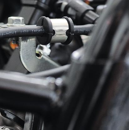
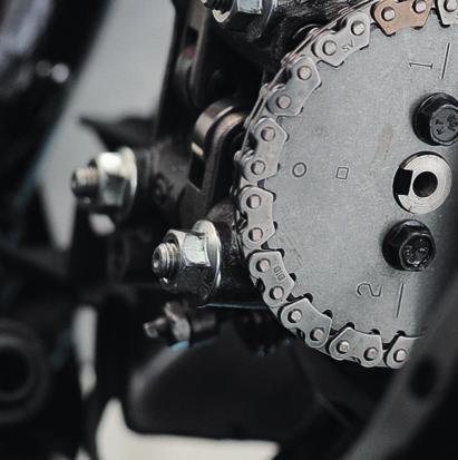
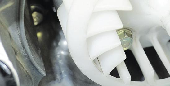
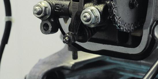
6 T O E G H F R Ç - Togliere la ruota posteriore e le viti o i perni che fissano il motore al telaio e all ammortizzatore posteriore. - questo punto avete svincolato il motore dal veicolo, e vi consigliamo di posizionarlo su di un banco di lavoro ben pulito e pronto alle successive operazioni oppure di bloccarlo su di una morsa. montaggio GRUPPO TERMCO - Togliere il coperchio punterie. - Portare il motore nella posizione di punto morto superiore nella fase di compressione, posizione evidenziata dalla posizione del riferimento presente sulla puleggia dell albero a camme (Fig. 1, part. 1) allineato al part. 2, e dalla posizione del riferimento presente sul volano (Fig. 2); allineare i riferimenti sul volano e sul carter come indicato in Fig Per far ruotare il motore servirsi del bullone di fermo dell albero motore. - nserire il cacciavite nel foro e ruotare la vite in senso orario fino al bloccaggio di fine corsa (Fig. 3, part. 3). - Remove the rear wheel and the screws or studs fastening the engine to the frame and rear shock absorber. - t this point, you have released the engine from the vehicle and we advise you to position it on a very clean workbench ready for the next procedures or to clamp it in a vice. CYDER KT disassembly - Remove the rocker cover. - Bring the engine to top dead centre in the compression stroke. The right position is shown by the reference mark found on the pulley of the camshaft (Fig. 1, point 1) lined up with point 2, and by the position of the reference mark found on the flywheel, Fig. 2, line up the reference marks on the flywheel and on the crankcase as shown in Fig n order to turn the engine, use the close bolt of the crankshaft. - nsert the screwdriver into the hole and turn clockwise the screw till complete locking, (Fig. 3, point 3). - Enlevez la roue arrière et les vis ou les goujons qui fixent le moteur au cadre et à l amortisseur arrière. - ce moment-là, le moteur est détaché du véhicule. ous vous conseillons de le mettre sur un plan de travail bien propre et prêt pour les opérations successives ou bien de le bloquer dans un étau. Démontage du GROUPE THERMQUE - Retirez le couvercle de culasse. - Portez le moteur dans la position du point mort supérieur dans la phase de compression. Cette position est mise en évidence par la présence des points de repère visibles sur la poulie de l arbre à cammes (Fig. 1, point 1) aligné au point 2, et par la présence du point de repère visible sur le volant du moteur (Fig. 2). lignez l indication entre le volant et le carter comme indiqué dans la Fig Pour faire tourner le moteur, utilisez le boulon de fermeture du vilebrequin. - nserez le tournevis dan le trou et tournez la vis dans le sens des aiguilles d une montre jusq au blocage de fin de coure (Fig. 3, point 3)
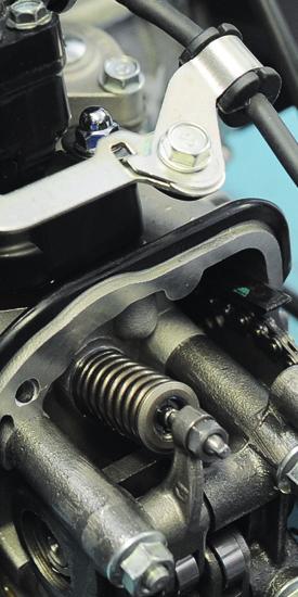
7 - Togliere il tendicatena e la corona dentata, avendo cura di non far cadere la catena di distribuzione sul basamento. - Togliere le due viti (Fig. 4, part. 5) che fissano la testa al basamento. - llentare i quattro dadi (Fig. 4, part. 6). - filare la testa ed il cilindro dal basamento del motore. - Rimuovere il pistone dalla biella. - Per maggior precauzione é buona norma chiudere il basamento con uno straccio pulito affinché non entrino corpi estranei nel basamento albero motore. - Remove the chain adjuster and the crown gear taking care not to let the gearing chain fall on the crankcase. - Remove the two screws (Fig. 4, point 5) which fix the cylinder head to the engine block. - crew out the four nuts (Fig. 4, point 6). - Remove the cylinder head and the original cylinder from the crankcase of the engine. - Remove the piston from the connecting rod. - s an extra precaution to prevent foreign matter from entering the crankshaft block, it is best to close the block with a clean cloth. - Retirez le tendeur de chaîne, puis la couronne dentée, en prenant soin de ne faire pas tomber la chaîne de distribution sur l embase. - Retirez les deux vis (Fig. 4, point 5) qui fixent la culasse à l embase. - Dévissez les quattre écrous (Fig. 4, point 6). - Démontez la culasse et le cylindre d origine de l embase du moteur. - Enlevez le piston de la bielle. - Pour plus de précautions et pour empêcher que des corps étrangers ne pénètrent dans l embase du moteur, en règle générale on ferme l embase avec un chiffon propre
8 T O E G H F R Ç Montaggio TET MOTORE e lo scooter non ha percorso molti chilometri si consiglia comunque di effettuare una prova di tenuta delle valvole seguendo le istruzioni come descritto al paragrafo Collaudo tenuta valvole. Qualora abbia invece percorso parecchi chilometri é consigliabile smontare le valvole e controllare che fra stelo e guide non vi sia eccessivo gioco, che le valvole non siano piegate oppure rechino gradini o che non abbiano il fungo logorato. nche in presenza di uno solo di questi casi si consiglia la sostituzione di entrambi i componenti; così pure dicasi per le molle richiamo valvole, se non risultano idonee. Eventualmente vedere Consigli utili. n caso di sostituzione delle guide valvola, sia per lo smontaggio sia per il montaggio, riscaldare preventivamente la testa usando un phon o un fornello elettrico. Dopo la sostituzione delle guide riprendere le sedi valvola con un apposita fresa per ripristinarle. merigliare le valvole con pasta abrasiva e ripulire la testata con tutti i suoi componenti dalle eventuali incrostazioni residue e dalla pasta abrasiva. CYDER HED assembly f the scooter does not have much mileage, we recommend you to perform the valve tightness test in any case, following the instructions found in the section entitled Valve tightness test. f the scooter has registered a lot of mileage, it is advisable to disassemble the valves and check to ensure that there is not excessive clearance between the valve stem and the guides, that the valves are not bent or present unevenness or a worn head. Even if only one of these conditions is found to exist, we advise you to replace both components, as well as the valve return springs, if the latter are not in perfect condition. f it is necessary, consult the Useful suggestions. n the event of valve guide replacement for both assembly and disassembly, the head must be heated prior to the procedure with a hair-dryer or electric hot plate. fter the replacement of the guides, re-condition the valve seats with a specific milling machine in order to restore them. Then grind the valve with abrasive paste and remove any remaining deposits and abrasive paste from the head and all head components. Montage de la CUE DU MOTEUR i le scooter n a pas parcouru beaucoup de kilomètres, il est tout de même conseillé d effectuer un test d étanchéité des soupapes en suivant les instructions décrites dans le paragraphe Test d Etanchéité des oupapes. i le scooter a déjà parcouru de nombreux kilomètres, il est conseillé de démonter les soupapes et de contrôler qu il n y ait pas trop de jeu entre la tige et les glissières, que les soupapes ne soient pas pliées, qu elles ne forment pas une marche ou que leur tête ne soit pas abîmée. En présence même d un seul de ces cas, il est conseillé de changer les deux composants ainsi que les ressorts de rappel des soupapes s ils ne sont pas adéquats. Eventuellement voir le paragraphe Conseils Utiles. i l on change les glissières des soupapes, tant pour le montage que pour le démontage, réchauffez préalablement la culasse avec un sèchecheveux ou un four électrique. près avoir changé les glissières, corrigez les sièges des soupapes avec une fraise spéciale de manière à les rétablir, puis rodez les soupapes avec de la pâte abrasive et nettoyez à nouveau la culasse et tous ses composants pour éliminer tous les éventuels déchets incrustés et la pâte abrasive
9 avare e sgrassare scrupolosamente poi rimontare le valvole come in origine dopo averne ben lubrificato gli steli, procedere alla prova di tenuta come descritto al paragrafo Collaudo tenuta valvole. ttenzione E indispensabile eseguire la spianatura della testa presso un officina specializzata. n alternativa strisciare la base di appoggio al cilindro della testa su di un foglio di carta abrasiva (di grana n 1000) poggiato su una superficie perfettamente piana sino a che tutta la superficie ne risulti interessata; a seguire lavare accuratamente tutta la testata (Fig. 5). Wash and degrease thoroughly then, after having well oiled their shanks, refit the valves as they were originally fitted. Then proceed with the tightness test as described in the section entitled Valve tightness test. ttention The head lapping in must be done by an authorised workshop. Otherwise clean the base of the cylinder head on a sheet of 1000 grade emery positionned on a perfectly flate surface plate until it is totally white; then carefully wash the cylinder head (Fig. 5). avez et dégraissez scrupuleusement les soupapes, huilez leurs tiges et remontez les comme elles étaient à l origine. Effectuez le test d étanchéité comme indiqué dans le paragraphe Test d Etanchéité des oupapes. ttention l est indispensable d effectuer l applanissement de la culasse dans un atelier specialisé. Une alternative est de passer la base d appuis du cylindre à la culasse sur une feuille de papier abrasif (grain de 1000) jusqu à ce que toute la surface soit nettoyée ensuite nettoyer avec attention toute la culasse (Fig. 5)
10 T O E G H ERMETO del CDRO l cilindro deve entrare liberamente nel carter motore; per evitare seri problemi comportarsi come segue. Preparazione al rimontaggio Pulire accuratamente il carter motore nella base di appoggio del cilindro da eventuali residui della guarnizione originale. Montare la guarnizione di base sul carter motore ed inserirvi le relative bussole di centraggio. Prima di iniziare il montaggio del gruppo Malossi prendere il cilindro lavarlo e sgrassarlo. Fare scendere il cilindro lungo i prigionieri di bloccaggio del gruppo termico e senza forzare imboccare il cilindro nel basamento motore. Verificare che non via siano all interno del carter parti grezze che impediscano il passaggio del canotto del cilindro o altri piccoli problemi che non consentono un inserimento libero del cilindro fino a battuta sul carter motore. n caso vi siano punti di attrito significativi si consiglia di asportarli. uperata questa fase, sfilare il cilindro e iniziare il montaggio seguendo le istruzioni seguenti. nserting the CYDER The cylinder should freely enter the crankcase and to avoid serious problems follow the instructions here below. Re-assembly preparation Clean the crankcase in the cylinder support base thoroughly, removing any residue from the original gasket. Mount the basic gasket on the crankcase and insert the respective truing bushes. Prior to starting to assemble the Malossi kit, take the cylinder, wash it and degrease it. Drop the cylinder along the cylinder unit locking stud bolts and without forcing it, fit it in the engine block. Check to ensure that there are no rough parts inside the crankcase preventing the passage of the cylinder steering shaft or other minor problems preventing free entry of the cylinder flush with the crankcase. n the event of significant blocked entry, we advise you to remove useless or damaging parts. Once this phase has been completed, slide off the cylinder and start the assembly according to these instructions. F R Ç ntroduction du CYDRE e cylindre doit entrer librement dans le carter du moteur et, pour éviter de sérieux problèmes, veuillez bien suivre les instructions suivantes. Preparation au remontage ettoyez soigneusement le carter du moteur dans la base d appui du cylindre pour éliminer les résidus éventuels du joint d origine. Montez le joint de base sur le carter du moteur et y insérez les douilles de centrage correspondantes. vant de commencer à monter le groupe Malossi, lavez le cylindre et dégraissez-le. Faites descendre le cylindre le long des goujons de serrage du groupe thermique et emboîtez, sans forcer, le cylindre dans l embase du moteur. Vérifiez qu il n y ait pas des parties brutes dans le carter du moteur qui bloquent le passage du fourreau du cylindre, ou des autres petits problèmes qui gênent l insertion fluide du cylindre en butée sur le carter du moteur. il y a des points de friction importants, il est recommandé d enlever les parties inutiles et créant des dégâts. Une fois cette phase terminée, retirez le cylindre et commencez le montage en suivant les instructions
11 Montaggio GRUPPO TERMCO - Pulire accuratamente il nuovo pistone e soffiarlo con aria compressa, controllando che non vi siano corpi estranei che ostruiscono i forellini di scarico nella cava del segmento raschiaolio. - Montare nel pistone uno dei due fermi spinotto, avendo cura di controllare che sia inserito perfettamente nella propria sede. - nserire il pistone sulla biella e fissarlo con il nuovo spinotto avendo avuto cura di oliarlo preventivamente. - nserire il secondo fermo spinotto controllando che sia posizionato correttamente nella propria sede. Montaggio EGMET (Fig. 6) - nserire la mollettina del segmento raschiaolio (5) nella apposita cava sul pistone, inserire la lamella inferiore (4) e successivamente la lamella superiore (3) che vanno a comporre il segmento raschiaolio (Fig. 7). - Montare il secondo segmento con la stampigliatura rivolta verso la parte superiore del pistone come indicato in Fig. 7. CYDER KT assembly - Clean the new piston thoroughly and blow it with compressed air. Ensure that there is no foreign matter blocking the small exhaust holes in the slot found on the scraper ring segment. - Fit one of the two spin locks in the piston, ensuring that it is perfectly inserted in its seat. - nsert the piston on the connecting rod and fasten it with the new spin lock. t must be oiled prior to this procedure. - nsert the second spin lock, ensuring that it is perfectly inserted in its seat. PTO RG assembling (Fig. 6) - nsert the small scraper ring segment spring (5) in the respective slot found on the piston. nsert the lower reed (4) and then the upper reed (3), which make up the scraper ring segment (Fig. 7). - Fit the second segment with the word facing the upper part of the piston as indicated in Fig. 7. Montage du GROUPE THERMQUE - ettoyez avec soin le nouveau piston et le souffler avec de l air comprimé; contrôlez qu il n y ait pas des corps étrangers qui bouchent les trous de sortie dans la rainure du segment racleur d huile. - Montez un des deux arrêts d axe de piston dans le piston et vérifiez qu il soit parfaitement inséré dans son emplacement. - nsérez le piston préalablement huilé sur la bielle et fixez le avec le nouvel axe de piston. - nsérez le second arrêt d axe de piston en contrôlant qu il soit positionné correctement dans son emplacement. MOTGE DE EGMET (Fig. 6) - nsérez le ressort du segment racleur d huile (5) dans la rainure spéciale se trouvant sur le piston, insérez la lamelle inférieure (4) puis la lamelle supérieure (3) qui vont composer le segment racleur d huile (Fig. 7). - Montez le second segment avec l estampillage tourné vers la partie supérieure du piston comme le montre la Fig
12 T O E G H F R Ç - nserire il primo segmento di compressione con l apertura sfasato rispetto al secondo segmento con la stampigliatura rivolta verso la parte superiore del pistone come indicato in Fig Posizionare i segmenti come indicato in Fig. 7. ervendosi della apposita pinza stringi segmenti inserire il nuovo cilindro Malossi, avendolo in precedenza oliato, mentre si fa avanzare attraverso il passaggio catena, situato nel cilindro, un gancetto con il quale si solleva la catena stessa; poi si cala il cilindro fino al basamento motore accertandosi che non vi siano impedimenti al perfetto appoggio del cilindro sulla base del carter motore. - Montare il pattino guida catena controllando che sia perfettamente alloggiato nella propria sede. - Montare la nuova guarnizione di testa e le due bussole di centraggio. - nfilare la testata sui prigionieri e servendosi del gancio estrarre la catena di distribuzione dalla testata. - errare i quattro dadi dei prigionieri con procedura a croce e con la coppia di serraggio indicata nella tabella Dati montaggio. - nserire le due viti M6 laterali che fissano la testa al basamento e serrarle applicando la coppia di serraggio indicata nella tabella - Fit the first compression segment with the opening dephased as regards to the second segment with the word facing the upper part of the piston as indicated in Fig Place the rings as indicated in Fig. 7. Using the special segment gripper pliers, insert the new Malossi cylinder after it has been oiled. hook serving to lift the chain itself should advance towards the chain passage found in the cylinder. Then the cylinder is dropped down to the engine block, ensuring that there is nothing blocking the cylinder from resting perfectly on the base of the crankcase. - Fit the chain guide shoe, checking to ensure that it is perfectly positioned in its seat. - Fit the new head gasket and the two truing bushes. - nsert the head on the stud bolts and use one hook to extract the gearing chain on the head. - Tighten the four stud bolt proceeding crosswise and with the tightening torque indicated in the table entitled ssembly data. - nsert the two lateral M6 screws fastening the head to the engine block and tighten them at the tightening torque indicated in the table entitled - Montez le premier segment de compression avec l ouverture désaxée par rapport au second segment avec l estampillage tourné vers la partie supérieure du piston comme le montre la Fig Positionnez les segments comme montré dans la Fig. 7. l aide d une pince serre-segments, insérez le nouveau cylindre Malossi préalablement huilé tout en faisant passer un crochet à travers le passage de la chaîne, situé dans le cylindre; ce crochet sert à soulever la chaîne. Puis, descendez le cylindre jusqu à l embase du moteur en vous assurant que rien n empêche le cylindre d appuyer totalement sur la base du carter du moteur. - Montez le patin de guidage de la chaîne en vérifiant qu il soit parfaitement en place dans son emplacement. - Montez le nouveau joint de la culasse et les deux douilles de centrage. - Enfilez la culasse sur les goujons et utilisez un crochet pour extraire la chaîne de distribution de la culasse. - errez en observant un ordre de serrage croisé les quatre écrous des goujons au couple de serrage indiqué dans le tableau Données de montage
13 Dati montaggio. - Posizionare l albero motore al punto morto superiore allineando il riferimento presente sul volano con il riferimento sul carter (Fig. 2). - Montare la catena di distribuzione sulla corona dentata ed inserirla sull albero a camme allineando la linea di riferimento (Fig. 1, part. 1) con il riferimento (Fig. 1, part. 2). - Mettere in tensione manualmente la catena di distribuzione agendo dal foro di montaggio del tendicatena e controllare che la corona dentata sia allineata al riferimento sulla testata, eventualmente spostare la catena di distribuzione di un dente in più o in meno sulla corona dentata. - Fare attenzione e controllare spesso che durante la messa in fase dell albero a camme non si muova l albero motore dalla posizione indicata dai due riferimenti allineati di Fig Procedere al montaggio del tendicatena serrando le 2 viti M6 sul cilindro e utilizzare il cacciavite per montare in senso antiorario la vite di fermo fino al suo blocco. - vvitare le 2 viti M6 sull albero a camme, bloccando in questo modo la corona dentata nella propria sede. Chiudere le 2 viti M6 con una coppia di ssembly data. - Bring the crankshaft to the top dead centre lining up the reference mark visible on the flywheel with the reference mark visible on the plastic crankcase (Fig. 2). - Fit the gearing chain on the crown gear and insert it on the camshaft, aligning the reference line (Fig. 1, point 1) with the reference (Fig. 1, point 2). - Tension the gearing chain manually from the gearing chain assembly opening and check to ensure that the crown gear is aligned with the reference on the head. f necessary, shift the gearing chain by one tooth more or one less on the crown gear. - Be careful to check often to ensure that the crankshaft is not moving during the timing of the camshaft from the position indicated by the two reference marks aligned as shown in Fig Proceed with chain adjuster assembly tightening the 2 M6 screws on the cylinder and using the screwdriver to turn counterclockwise the locking screw till complete locking. - nsérez les deux vis M6 latérales qui fixent la culasse à la base et serrez-les en appliquant le couple de serrage indiqué dans le tableau Données de montage. - Positionnez le vilebrequin au point mort supérieur en alignant le point de repère présent sur le volant du moteur avec le point de repère présent sur le carter (Fig. 2). - Montez la chaîne de distribution sur la couronne dentée et introduisez-la sur l arbre à cames en alignant la ligne de repère (Fig. 1, point 1) avec le repère (Fig. 1, point 2). - Tendez manuellement la chaîne de distribution en agissant depuis le trou de montage du tendeur de chaîne et contrôlez que la couronne dentée soit alignée avec le repère sur la culasse, déplacez éventuellement la chaîne de distribution d une dent en plus ou en moins sur la couronne dentée. - Contrôlez souvent que, pendant la mise en phase de l arbre à cames, le vilebrequin ne bouge pas de la position indiquée par les deux repères alignés (Fig. 2). - Montez le tendeur de chaîne en serrant le 2 vis M6 sur le cylindre et utilisez le tournevis pour tourner la vis dans le sens contraire des aiguilles d une
14 T O E G H F R Ç serraggio come indicato nello specchietto dei Dati montaggio. - Con una chiave a bussola con manico a T, agendo sul dado presente sull albero motore e che fissa il variatore far compiere all albero motore 4-5 giri completi e riportarlo al punto morto superiore allineando i riferimenti di Fig. 2 e controllare che la corona dentata della catena di distribuzione sia ancora allineata con il riferimento come da Fig. 1. e durante la rotazione l albero motore si dovesse bloccare assolutamente non tentare di forzarlo ma controllare la messa in fase della distribuzione che evidentemente non é stata eseguita correttamente e rifare la messa in fase seguendo scrupolosamente la procedura suindicata. - Dopo aver verificato che l albero motore si trovi al punto morto superiore Fig. 2 e l albero a camme come indicato in Fig. 1, controllare ed eventualmente ripristinare il corretto gioco valvola di scarico e di aspirazione. l valore del gioco delle valvole é indicato nella tabella Dati montaggio. - Rimontare il coperchio. - Turn in the 2 M6 screws on the camshaft, in order to block the crown gear in its seat. Close the 2 M6 screws applying the tightening torque indicated in the table entitled ssembly data. - Using a socket wrench with a T-shaped handle, and intervening on the nut found on the crankshaft and that fastens the variator unit make all the engine have 4-5 complete revolutions and bring it back to the top dead centre, aligning the references shown in Fig. 2 and check to ensure that the gearing chain crown gear has remained aligned with the reference mark on the head (Fig. 1). f the crankshaft is blocked during the rotation, do not attempt absolutely to force it under any circumstances. Check the timing of the timing system, which evidently was not performed properly. Then repeat the timing process and follow meticulously the procedure indicated here above. - fter having checked to ensure that the crankshaft is at the top dead centre (Fig. 2) and the camshaft is positioned as indicated in Fig. 1, check and if necessary correct the exhaust and intake valve for the proper clearance. The value clearance is specified in the table entitled ssembly data. montre jusqu au blocage. - Vissez les 2 vis M6 sur l arbre à cammes, en bloquant ainsi la couronne dentée dans son enplacement. Fermez les 2 vis M6 avec le couple de serrage indiqué dans le tableau Données de montage. - vec une clé à douille mâle à béquille, agissez sur l écrou de l arbre à cames qui fixe le groupe variateur, faites faire 4-5 tours complets au vilebrequin, puis remettez-le au point mort supérieur en alignant les repères de la Fig. 2 contrôlez que la couronne dentée de la chaîne de distribution soit encore alignée avec le repère (Fig. 1). i, pendant la rotation, le vilebrequin se bloque, vous ne devez absolument pas essayer de le forcer mais contrôlez la mise en phase de la distribution car il est évident qu elle n a pas été exécutée correctement, et refaites-la en suivant scrupuleusement la procédure décrite précédemment. - près avoir vérifié que le vilebrequin du moteur se trouve au point mort supérieur (Fig. 2) et que l arbre à cammes soit dans la position indiquée Fig. 1, contrôlez et éventuellement rétablissez le jeu correct de la soupape d échappement et d admission. a valeur du jeu des soupapes est
15 - mmettere nel motore la quantità di olio Malossi 7.1 indicata nella tabella Dati montaggio del tipo raccomandato dalla casa costruttrice del veicolo. - Controllare la candela e ripristinare eventualmente la distanza degli elettrodi o sostituirla con una del tipo indicato nella tabella Dati montaggio. - Rimontare il motore sul veicolo e ripristinare tutti i collegamenti come in origine. - Re-assemble the cover. - Put in the engine the amount of Malossi 7.1 oil indicated in the table entitled ssembly data, using the type of oil recommended by the manufacturer of the vehicle. - Check the spark plug and if necessary, re-adjust the distance of the electrodes or replace it with one of the types indicated in the table entitled ssembly data. - Re-mount the engine on the vehicle and reconnect all connections as they were originally. indiquée dans le tableau Données de montage. - Remontez le couvercle. - Versez dans le moteur la quantité d huile Malossi 7.1 indiquée dans le tableau Données de montage ; utilisez l huile du type conseillé par le constructeur du véhicule. - Contrôlez la bougie et, éventuellement rétablissez la distance entre électrodes ou remplacez-la avec une bougie du type indiqué dans le tableau Données de montage. - Remontez le moteur sur le véhicule et reprenez tous les branchements comme ils étaient à l origine
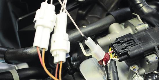
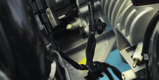
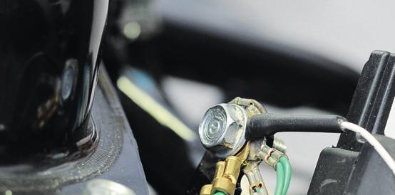
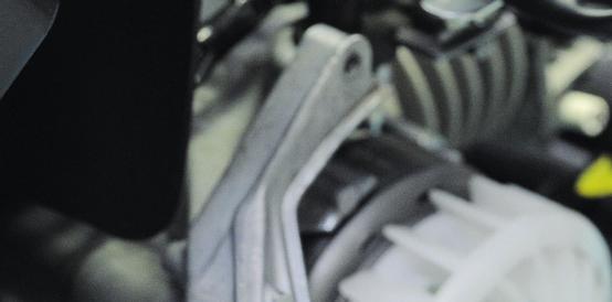
16 T O E G H Montaggio centralina (Fig. 15) - Posizionare la centralina Force Master 0 nel vano sottosella e inserire i cavi nello scooter portandoli al motore, avendo cura che non rimangano danneggiati. - pplicare al cavo bianco/rosso che fuoriesce dal connettore TP posizionato sul corpo farfallato il rubacorrente fornito nel kit Malossi (Fig. 8, part. 8) - Collegare il cavo bianco con faston maschio proveniente dalla centralina al rubacorrente (Fig. 8, part. 7). TTEZOE: una volta collegato il connettore al rubacorrente suggeriamo di nastrare il gruppo cavi, in modo da evitare che le oscillazioni del rubacorrente causate dalle vibrazioni del motore usurino i cavi stessi. - eguire il filo che esce dall iniettore e tagliarlo a 3 cm circa dal connettore, come indicato in Fig Collegare il connettore femmina () fornito nel kit al connettore originale (B) utilizzando il raccordo (C), rispettando scrupolosamente i colori dei cavi (Fig. 11). B: prestare attenzione ad utilizzare il faston FEMM!!! CD assembly (Fig. 15) - Position the Force Master 0 CD into the helmet holder and run the wires to the engine, taking care that they will not be damaged. - pply the splice, supplied in the Malossi kit, to the white/red wire that exits the TP connector on the butterfly housing (Fig. 8, part. 8) - Connect the white wire with male faston which comes from the CD to the electrical tap connector (Fig. 8, part. 7). WRG: once the faston is connected to the electrical tap connector we suggest to tape the wire bunch, to avoid electrical tap vibrations damaging the wires. - Follow the wire coming out of the injector and cut it at about 3 cm from the connector, as shown in Fig Connect the female faston () supplied into the kit to the original connector (B) by using the joint (C), and carefully respecting the colours of the wires (Fig. 11). B: pay attention to use the FEME faston!!! F R Ç Montage boîtier éléctronique (Fig. 15) - Positionnez le boîtier éléctronique Force Master 0 dans le coffre porte-casque et insérez les câbles dans le scooter en les menant au moteur, en prenant soin de ne pas les abimer. - ppliquer sur le câble blanc/rouge sortant du connecteur TP se trouvant sur le corps pipillon le vol courant fournis dans le kit Malossi (Fig. 8, part. 8) - Connectez le câble blanc avec faston mâle en provenance du boîtier éléctronique à l aiguille prise de tension (Fig. 8, part. 7). TTETO: après avoir connecté le connecteur à l aiguille prise de tension nous vous conseillons de guiper le groupe câbles pour éviter que les oscillations de l aiguille, provoqués par les vibrations du moteur, usent les câbles. - uivre le fil qui sort de l injecteur et coupez-le à 3 cm environ du connecteur, comme indiqué dans la Fig Connecter la cosse faston femelle () fourni dans le kit au connecteur d origine (B) en employant le raccord (C) et respectant soigneusement les couleurs des câbles (Fig. 11). B: prêter attention à utiliser la cosse faston FEMEE!!!
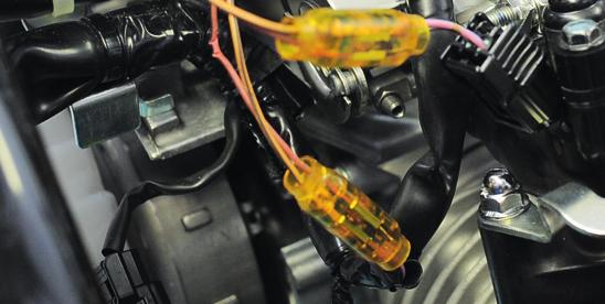
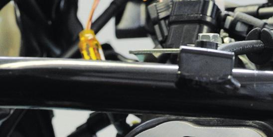
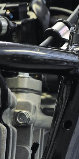
17 - Chiudere il raccordo servendosi di una pinza, come indicato in Fig questo punto, collegare il connettore maschio (11) ai cablaggi del veicolo, servendosi del raccordo, come indicato in Fig. 13, rispettando lo schema seguente: arancio/nero -> rosa/blu rosso/nero -> bianco/nero - eguire il filo che esce dall iniettore e individuare il connettore, collegando i due connettori presenti sulla centralina Malossi (Fig. 3, part. 4). - Collegare il cavo bianco con occhiello che esce dalla centralina Malossi al nodo di massa (Fig. 10, part. 9). - ndividuare il faston PCCOO (cavo giallo) inserito nella bobina originale e scollegarlo. - nserire il faston proveniente dalla centralina Malossi alla bobina accensione. - Riconnettere al bypass il cavo originale per chiudere il circuito (Fig. 10, part. 10). - Fissare la centralina. - Close the joint using a pliers, such as shown in Fig t this point connect the male faston (11) to the wiring of the vehicle, using the joint as shown in Fig. 13, following this scheme: orange/black -> pink/blue red/black -> white/black - Follow the wire that exits the injector and determine its connector, disconnect this original connector and reconnect with the two connectors from the Malossi ECU (Fig. 3, part. 4). - Connect the white wire with eyelet which comes from the Malossi CD to the ground node (Fig. 10, part. 9). - ocate the M faston (yellow wire) connected to the original coil and disconnect it. - nsert the faston which comes from the Malossi ECU to the original coil. - Connect the original wire to the ECU s bypass to complete the circuit (Fig. 10, part. 10). - Fix the CD. - Fermer le raccord en utilisant des pinces, comme indiqué dans la Fig Á ce point là, connecter la cosse faston mâle (11) aux câbles du véhicule en utilisant le raccord, comme indiqué dans la Fig. 13, en respectant le schéma suivant: orange/noir -> rose/bleu rouge/noir -> blanc/noir - uivre le fil sortant de l injection et individualisez le connecteur, en y connectant les 2 connecterus présent sur le boîtier Malossi (Fig. 3, part. 4). - Connectez le câble blanc avec oeillet provenant du boîtier Malossi au noeud de masse (Fig. 10, part. 9). - ocalisez le connecteur faston PETT (câble jaune) inséré dans la bobine d origine et déconnectez-le. - nsérez le connecteur faston en provenance du boîtier électronique Malossi à la bobine. - Connectez le câble d origine au bypass pour fermer le circuit (Fig. 10, part. 10). - Fixez le boîtier
18 T O l cavo bianco con bullet femmina deve rimanere inutilizzato. Posizionarlo in modo che non interferisca con altre parti e/o cablaggi. TTEZOE: Qualora si voglia riportare il veicolo allo stato originale, sarà sufficiente staccare i connettori della centralina e ricollegare i due connettori Malossi (Fig. 14). The white wire with female bullet is not used. Position it so it does not interfere with other wires or parts. E G H WRG: f you want to bring the vehicle back to its original condition, you must simply disconnect the cdi connectors and reconnect the Malossi connectors (Fig. 14). F R Ç e câble blanc ave bullet femelle doit rester inutilisé. Positionnez-le de telle façon qu il n interagisse pas avec les autres parties et/ou cablâges. TTETO: Dans le cas on veuille remettre le véhicule à son état d origine, il sera suffisant détacher les connecteurs du boitier et reconnecter les deux connecteurs Malossi (Fig. 14)
19 Taratura TP (throttle position sensor) Fig Ruotare il trimmer sulla freccia rossa (rivolto a ore 6). - Ruotare la chiave del veicolo su O. - ttendere la completa accensione dei 3 led e il successivo spegnimento. - Ruotare la chiave del veicolo su OFF. - prire completamente la manopola del gas. - Ruotare la chiave del veicolo su O. - ttendere la completa accensione dei 3 led e il successivo spegnimento. - Ruotare la chiave del veicolo su OFF. - Ruotare il trimmer sulla mappa desiderata. e nella procedura di taratura di M e MX il led rosso lampeggia significa che la procedura non è stata eseguita correttamente e che la manopola TP (Throttle Position ensor) Calibration Fig Rotate the trimmer to the red arrow position (pointed at 6 o clock position). - Turn the ignition key to the O position. - Wait for all three (3) EDs to illuminate and then turn off. - Turn the ignition key to the OFF position. - Turn the throttle to the fully open position. - Turn the ignition key to the O position. - Wait for all three (3) EDs to illuminate and then turn off. - Turn the ignition key to the OFF position. - Rotate the HGH trimmer to the desired map. f the red ED starts blinking while calibrating the M and MX, this means that procedure has not been carried out correctly and that the throttle Réglage TP (Throttle position sensor) Fig Tournez le trimmer sur la flèche rouge (tourné à heures 6). - Tournez la clé du véhicule sur O. - ttendre l allumage complet des 3 leds et ensuite l arrêt complet de celles-ci. - Tournez la clé du véhicule sur OFF. - Ouvrez complètement la poignée GZ. - Tournez la clé du véhicule sur O - ttendre l allumage complet des 3 leds et ensuite l arrêt complet de celles-ci. - Tournez la clé du véhicule sur OFF. - Tournez le trimmer sur la courbe désirée. i dans la procédure de réglage du M et du MX le led Rouge clignotte cela signifie que la procédure n a pas été exécutée correctement et que la
 se il trimmer è posizionato sulla freccia rossa non è possibile avviare il veicolo. Fig. 16 E G H was not positioned correctly. n this case, re-do the TP calibration procedure from the start.")
20 T O del gas non era nella posizione richiesta. n questo caso eseguire nuovamente la taratura del TP. TTEZOE: (Fig. 16) se il trimmer è posizionato sulla freccia rossa non è possibile avviare il veicolo. Fig. 16 E G H was not positioned correctly. n this case, re-do the TP calibration procedure from the start. TTETO: (Fig. 16) if the trimmer is positioned on a red arrow then the vehicle will not start. F R Ç poignée de gaz n était pas dans la position requise. Dans ce cas, refaites de nouveau le réglage du TP. TTETO: (Fig. 16) si le trimmer est positionné sur la flèche rouge il ne sera pas possible d allumer le véhicule
21 DGOTC ulla centralina sono presenti 3 led di diverso colore (Fig. 15): ROO : indicazione avaria centralina. e a veicolo acceso il led rosso si illumina significa che c è un avaria. e principali cause di avaria possono essere: 1. Tensione batteria troppo bassa o alta 2. Cavo iniettori danneggiato che urta parte del telaio 3. Centralina danneggiata RCOE : indica l avvenuta variazione della regolazione dei trimmer. VERDE : il led verde acceso indica il corretto funzionamento della centralina. e a chiave O il led verde non si illumina significa che la centralina non riceve corrente. Per risolvere il problema procedere con la verifica dei cablaggi per controllare che questi siano stati eseguiti correttamente. DGOTC The ECU has three (3) different colored EDs (Fig. 15): RED : indicates a damaged ECU. damaged ECU is indicated if the red ED illuminates while the vehicle is running. The principal causes for this problem are: 1. Battery voltage too low or too high. 2. Fuel injection cable is damaged due to interference with the frame 3. Damaged ECU. MBER : indicates the trimmers have been adjusted correctly. GREE : indicates the ECU is functioning correctly, if the green ED does not illuminate when the ignition is switched on, then this indicates no power to the ECU. Make sure that you have properly connected the wiring harness. DGOTC ur le boîtier électronique sont présentes 3 led de couleurs différentes (Fig. 15): ROUGE : indique une avarie sur le boîtier. i a véhicule allumé la led rouge est illuminé cela signifie qu il y a une avarie. es princiaples causes d avaries peuvent être: 1. Tension de la batterie trop haute ou trop basse 2. Câbles des injecteurs endommagés touchant une partie du cadre 3. Boîtier CD endommagé ORGE : indique la variation du réglagle du trimmer. VERT : a led vert allumé indique le correct fonctionnement du boîtier. i avec la clé O la led verte ne s éclaire pas, le boîtier ne reçoit pas le courant. Pour résoudre le problème il faut vérifier les câblages pour contrôler qu ils soient corrects
22 T O E G H Funzionamento a centralina Force Master 0 è mappata con 3 curve di base. e curve sono selezionate usando il commutatore contrassegnato con MP. Queste curve regolano il flusso di carburante in base a posizione del corpo farfallato e RPM, fornendo la giusta quantità di carburante in ogni condizione. e 3 curve di alimentazione corrispondono a diversi livelli di mappatura. livelli di mappatura sono suddivisi nei seguenti gruppi: curva 1 - Motore tutto originale e limitatore spostato a rpm curva 2 - Kit Malossi ø 49 mm - carico originale - Camme originale curva 3 - Kit Malossi ø 49 mm - carico Malossi - Camme originale Oltre alle 3 curve è possibile mettere a punto ulteriormente la curva selezionata regolando la curva del carburante da +6% a 6% in tutti i differenti range di RPM. Working The Force Master 0 CD is preprogrammed with 3 base fuel curves. The curves are selected using the switch labeled MP. These curves adjust fuel delivery based on throttle position and RPM, providing the right amount of fuel under all conditions. The 3 fuel curves correspond to varying levels of modifications. The levels of modification are broken down into the following groups: curve 1 - Whole original engine and limiter shifted at rpm curve 2 - Kit Malossi ø 49 mm - Original exhaust system- Original camshaft curve 3 - Kit Malossi ø 49 mm - Malossi exhaust system - Original camshaft n addition to the 3 curves it is possible to fine tune the curve you select, adjusting the fuel curve from +6% to 6% in all different RPM ranges. F R Ç Fonctionnement e boîtier éléctronique Force Master 0 est programmé avec 3 courbes différentes. Pour selectionner les courbes il faut utiliser le commutateur marqué avec MP. Ces courbes règlent le flux d essence sur la base de position du corps à papillon et RPM, en fournissant l exacte quantité d essence dans chaque condition. es 3 courbes correspondent à différents niveaux de progammation. es niveaux de programmation sont subdivisés dans les groupes suivants: courbe 1 - Moteur tout d origine et limiteur décalé à tours courbe 2 - Kit Malossi ø 49 mm - Pot d échappement d origine - rbre à cames d origine courbe 3 - Kit Malossi ø 49 mm - Pot d échappement Malossi - rbre à cames d origine En plus des 3 courbes est possible de régler ultérieurement la courbe selectionnée, en réglant la courbe du carburant de +6% à 6% dans tous les ranges de RPM différents
23 Per aumentare il flusso di carburante ruotare il trimmer in senso orario. Per diminuire il flusso, ruotare il trimmer in senso antiorario. Con il trimmer posizionato sullo zero (rivolto a ore 12) si ha una regolazione dello 0%. Con il trimmer posizionato sul segno - si ha una regolazione di 6%. Con il trimmer posizionato sul segno + si ha una regolazione di +6%. Regolando il trimmer tra questi due punti si aggiungerà o sottrarrà una quantità di carburante proporzionale a quanto la tacca viene spostata dallo zero. Regolazione a centralina è dotata di un unico trimmer a due quadranti: - Quadrante interno (numeri bianchi su fondo nero): regolazione delle mappe - Quadrante esterno (numeri neri): regolazione variazione % della curva carburante Volendo per esempio selezionare una curva senza variazione %, posizionare il trimmer a ore 12 sui numeri bianchi su fondo nero, scegliendo la mappa To add fuel, turn the trimmer clockwise. To subtrac fuel, turn the trimmer counterclockwise. With the trimmer pointed straight up at the zero mark (pointed at 12 o clock position), that is 0% adjustment. With the trimmer pointed straight up at the - mark is 6%. With the trimmer pointed straight up at the + mark is +6%. djusting the trimmer between these points will result in adding or subtracting an amount of fuel proportional to how far the knob was moved from zero. djustment The coil is provided with only one trimmer with two quadrants: - nternal quadrant (white numbers on black background): adjustment of the maps - External quadrant (black numbers): adjustment of % variation of fuel curve For example, if you want to select a curve without % variation, point the trimmer at 12 o clock position on white numbers on black background, Pour augmenter le flux du carburant tournez le trimmer dans le sens des aiguilles d une montre. Pour diminuer le flux, tournez le trimmer dans le sens inverse des aiguilles d une montre. vec le trimmer positionné sur le zero (tourné à heures 12) on a une régulation du 0%. vec le trimmer positionné sur l enchoce - on a une régulation de 6%. vec le trimmer positionné sur l enchoce + on a une régulation de +6%. En réglant le trimmer entre ces deux positions vous pouvez ajouter ou enlever une quantité de carburant proportionelle au déplacement de l enchoce du zero. Réglage e boîtier est équipé avec un seul trimmer à deux cadrans : - Cadran interne (nombres blanc su fond noir): réglage des courbes
24 T O di interesse. a selezione è facilitata dal lampeggio del led arancione, che si illuminerà tante volte quanto è il numero della mappa selezionata (mappa 1, un lampeggio del led arancione). Procedere alla stessa maniera qualora si desideri variare la percentuale della curva carburante. Qualora la configurazione/preparazione del vostro veicolo non corrisponda a quella indicata nel paragrafo Funzionamento, è possibile procedere con un ulteriore messa a punto regolando i potenziometri come suindicato. TTEZOE: si raccomanda di non procedere con le regolazioni con veicolo in movimento. E G H selecting the chosen map The selection is made easier by the winking of the orange led which will light up as many times as the number of the map (map number 1, one winking of orange led) Go on in the same way if you want to change the percentage of the fuel curve. n case the configuration/setting of your vehicle does not correspond to any of those indicated in the paragraph Working, it is possible to get a new tuning adjusting the potentiometers as above explained. WRG: do not attempt to adjust while riding. F R Ç - Cadran externe (nombres noirs): réglage variation % de la courbe du carburant i on veut, par exemple, sélectionner une courbe sans variation %, il faut positionner le trimmer à heurs 12 sur le nombres bancs sur fond noir en choisissant la courbe qui intéresse. a sélection est facilitée par le clignotement du led orange qui s illuminera autant de fois que le numéro de la courbe sélectionné (courbe 1, 1 clignotement du led orange). Effectuer les mêmes opérations si on veut varier le pourcentage de la courbe carburant. i la configuration/préparation de votre véhicule ne correspond pas à celle indiquée dans le paragraphe Fonctionnement, il est possible de régler ultérieurement les potentiomètres comme indiqué précédemment TTETO: nous vous recommandons de ne pas régler le véhicule en marche.
25 tato di funzionamento Ogni volta che viene girata la chiave su O si accendono simultaneamente i 3 led presenti sulla centralina. uccessivamente il led giallo lampeggia indicando la mappa impostata. seguire resta acceso il led verde a conferma del normale funzionamento della centralina. TTEZOE: in alcuni veicoli dopo aver girato la chiave su O nel caso in cui non si proceda con l avviamento entro 3/5 secondi la centralina gestione motore originale del veicolo toglie l alimentazione al sistema. RODGGO e MUTEZOE Per il rodaggio e la manutenzione attenersi scrupolosamente al manuale Uso e manutenzione del veicolo. tate of working Whenever the key is turned O, the 3 leds placed on the coil will switch on simultaneously. Then the yellow led winks indicating the setup map. Finally, the green led remains switched on confirming the proper working of the coil. TTETO: on some vehicles, if the starting is not made in 3/5 seconds after turning the key O, the original engine coil of the vehicle will take off the power to the system. RUG and MTECE For running in and maintenance, follow the instructions found in the Vehicle use and maintenance manual meticulously. État de fonctionnement Chaque fois qu on tourne la clé sur O les 3 led sur le boîtier s allument simultanément. Ensuite, le led jaune clignote en indiquant la courbe établie. Enfin, le led vert reste allumé en confirmant le fonctionnement normale du boîtier. TTETO : ur quelques véhicules, après avoir tourné la clé sur O, si on ne fait pas le démarrage dans 3/5 secondes, le boîtier de gestion moteur d origine du véhicule coupe l alimentation. RODGE et MTECE Pour rodage et maintenance s en tenir scrupuleusement à la notice Utilisation et entretien du véhicule pour le rodage et l entretien
26 T O DT MOTGGO - Coppia di serraggio dadi ciechi dei prigionieri M7 18 m (1,8 kgm) - Coppia serraggio viti M6 laterali testa 10 m (1 kgm) - Coppia di serraggio viti M5, corona dentata, albero a camme 10 m (1 kgm) - Capacità totale olio motore 0,8 litri Tipo: vedi manuale originale Uso e manutenzione - Candela tipo/fabbricante GKCR7H- 9 Distanza elettrodi 0,8 ~ 0,9 mm - Gioco valvole scarico: 0,20 mm aspirazione: 0,15 mm E G H EMBY DT - Tightening torque for M7 cap nuts of the stud bolts 18 m (1.8 kgm) - Tightening torque for M6 lateral nuts fastening the head 10 m (1 kgm) - Tightening torque for M5 screws, crown gear and camshaft 10 m (1 kgm) - Total engine oil capacity 0.8 litres Type: original the original Use and maintenance handbook - parkplug - type/manufacturer GKCR7H- 9 Electrode distance 0.8 ~ 0.9 mm - Valve clearance exhaust: 0.20 mm intake: 0.15 mm F R Ç DOEE DE MOTGE - Couple de serrage des écrous borgnes des goujons M7 18 m (1,8 kgm) - Couple de serrage des vis M6 latérales de la culasse 10 m (1 kgm) - Couple de serrage des vis M5, couronne dentée, arbre à cames 10 m (1 kgm) - Capacité totale huile du moteur 0,8 litres Type : voir la notice d origine Utilisation et entretien - Bougie : type/constructeur GKCR7H- 9 Distance entre les électrodes 0,8 ~ 0,9 mm - Jeu des soupapes échappement: 0,20 mm admission: 0,15 mm
27 Collaudo tenuta valvole spirazione e scarico: effettuare prove una di seguito all altra. Versare benzina nel condotto fino a riempirlo soffiare con una pistola ad aria compressa attorno al fungo della valvola in esame e controllare se all interno del condotto appaiono delle bollicine d aria. n caso affermativo occorre smontare la valvola ed effettuare la smerigliatura anche se questa operazione é già stata fatta, ed eventualmente ripetere l operazione fino a quando il fenomeno delle bollicine non verrà a cessare. Durante la prova controllare che il paraolio applicato alla guida non lasci trafilare carburante altrimenti sostituirlo con uno nuovo. COG UT i consiglia di smerigliare le valvole di scarico e aspirazione ogni qualvolta si smonta la testata. a smerigliatura va eseguita con apposito attrezzo e con una buona pasta abrasiva fine specifica per smerigliatura valvole. Per migliorare il rendimento del motore é consigliato eseguire una perfetta raccordatura e lucidatura dei condotti di aspirazione e scarico. Valve tightness test ntake and exhaust: perform the tests one after the other. Pour gasoline into the pipeline until it is filled. Use a compressed air gun to blow along the head of the particular valve and check whether air bubbles appear inside the pipeline. f so, the valve must be disassembled and grinding performed even if this procedure has already been carried out. t may also be necessary to repeat the procedure as many times as needed until the air bubbles no longer appear. When performing the test, check to ensure that the oil seal on the guide is not leaking fuel. f there is leakage, replace it with a new one. UEFU UGGETO We advise you to grind in the exhaust and intake valves whenever the head is disassembled. Grinding must be carried out using the specific tool and a satisfactory fine abrasive paste designed for grinding valves. To improve the performance of the engine, it is advisable to perform a perfect jointing and finishing of the intake and exhaust lines. The best intake line is a line tending to narrow slightly from the carburettor valve on to the intake valve with a maximum cam angle of 2. Test d etancheite des soupapes oupape d admission et d échappement : faites les essais sur une soupape après l autre. Remplissez le conduit d essence; soufflez avec un pistolet à air comprimé autour de la tête de la soupape en examen; contrôlez si des bulles d air apparaissent dans le conduit. i c est le cas, vous devez démonter la soupape et effectuer le rodage, même si cette opération a déjà été effectuée. Eventuellement, répétez l opération jusqu à ce que les bulles d air disparaissent. Pendant l essai, contrôlez que le segment racleur appliqué sur la glissière ne laisse pas s écouler du carburant; si c est le cas, changez-le avec un nouveau segment racleur. COE UTE ous vous conseillons de roder les soupapes d échappement et d admission à chaque fois que vous démontez la culasse. e rodage doit être effectué avec un outillage spécial et une bonne pâte abrasive fine pour rodage de soupapes. Pour améliorer le rendement du moteur, nous vous conseillons d effectuer un raccordement et un polissage parfaits des conduits d admission et d échappement. e meilleur conduit d admission est
28 T O E G H F R Ç l condotto di aspirazione ottimale é un condotto che tende leggermente a restringersi a partire dalla valvola del carburatore fino alla valvola di aspirazione con un angolo di chiusura massimo di 2 e nel contempo non deve presentare nessun tipo di asperità (spigoli, allargamenti o restringimenti bruschi) pertanto va perfettamente raccordato. l condotto di scarico ottimale presenta un andamento leggermente divergente a partire dalla valvola di scarico (con un angolo di apertura massima di 2 ) ed esente da qualsiasi asperità; pertanto perfettamente raccordato in tutti i passaggi fino al silenziatore di scarico, anche in questo caso non vi devono essere brusche riduzioni di passaggio o aumenti di sezioni di passaggio. VVERTEZE GEER Ogni qualvolta venisse smontato il gruppo termico sostituire le guarnizione di testa e base cilindro con una nuova serie, onde garantire una perfetta tenuta. on chiedere mai la massima prestazione al motore prima del raggiungimento della temperatura ottimale d esercizio, mantenere sotto controllo il sistema di lubrificazione del motore, il livello dell olio e la qualità dell olio lubrificante. t the same time, it should not have any protuberances of any type (edges, expansions or abrupt narrow points). Thus, the jointing must be carried out perfectly. The best exhaust line diverts slightly starting from the exhaust valve (with a maximum opening angle of 2 ). o protuberances of any type are present. Therefore, it is perfectly jointed in all sections up to the exhaust silencer. n this case as well, there must not be any abrupt reductions in passage or increases in the passage sections. GEER CRE Every time the cylinder kit is disassembled, replace the head and cylinder bottom gaskets with a new series in order to guarantee a perfect seal. ever demand maximum performance from the engine until it has reached its optimum working temperature. Control often the oil circuit of the engine, the oil level, and the oil quality. We hope you found the above instructions sufficiently clear. However, if any points are not particularly clear, please contact us completing the un conduit qui tend à se resserrer légèrement à partir de la soupape du carburateur jusqu à la soupape d admission avec un angle de fermeture maximum de 2 ; en même temps, il ne doit présenter aucun type d aspérités (arêtes, élargissements ou rétrécissements brutaux). l doit donc être parfaitement raccordé. e meilleur conduit d échappement est légèrement divergent à partir de la soupape d échappement (avec un angle d ouverture maximum de 2 ) et ne présente aucune aspérité; il doit donc être parfaitement raccordé à tous les passages jusqu au silencieux d échappement. Dans ce cas aussi il ne doit pas y avoir de réductions de passage ou des augmentations de sections de passage brusques. OTCE GEERE i le groupe thermique est démonté, remplacez les joints de culasse et de base du cylindre par une nouvelle série, afin de garantir une étanchéité parfaite. e jamais demander une performance maximum au moteur tant qu il n a pas atteint la température optimale d exercice. Contrôlez souvent le circuit d huile du moteur, le niveau et la qualité de l huile
29 periamo che lei abbia trovato sufficientemente esaustive le indicazioni che precedono. el caso in cui qualche punto le risultasse poco chiaro, potrà interpellarci per iscritto compilando l apposito modulo inserito nella sezione contatti del ns. sito nternet ( Ringraziamo fin d ora per le osservazioni e suggerimenti che vorrà eventualmente farci pervenire. a Malossi si commiata e coglie l occasione per complimentarsi ulteriormente con ei ed augurarle un Buon Divertimento. n BOCC al UPO e... alla prossima. e descrizioni riportate nella presente pubblicazione, si intendono non impegnative. Malossi si riserva il diritto di apportare modifiche, qualora lo ritenesse necessario, al fine di migliorare il prodotto, e non si assume nessuna responsabilità per eventuali errori tipografici e di stampa. a presente pubblicazione sostituisce ed annulla tutte le precedenti riferite agli aggiornamenti trattati. GRZ. Consulta le condizioni relative alla garanzia sul nostro sito Prodotti riservati esclusivamente alle competizioni nei luoghi ad esse destinate secondo le disposizioni delle competenti autorità sportive. Decliniamo ogni responsabilità per l uso improprio. special form inserted in the contact section on our nternet site ( We thank you in advance for any comments and suggestions you may wish to send us. o goodbye from us all at Malossi, and please accept our compliments. Have Fun. GOOD UCK and see you next time. The descriptions in this publication are not binding. Malossi reserves the right to make modifications, if it considers them necessary, and does not accept any responsibility for any typographic or printing errors. This publication replaces all previous publications referring to the updating matters contained therein. WRRTY. ook up warranty terms in our website These products are reserved solely for races in locations reserved for those purposes and in accordance with the regulations issued by the competent authorities for sports events. We decline any and all responsibility for improper use. ous espérons que vous avez trouvé suffisamment claire les indications qui ont précédé. Dans le cas ou certains points ne vous seraient pas clairs, ils vous est possible de nous interpeller en remplissant le module se trouvant dans la section contact de notre site internet ( ous vous remercions d avance des éventuelles observations et suggestions que vous voudrez bien nous faire parvenir. Malossi prend maintenant congé et profite de l occasion pour vous féliciter une fois encore et vous souhaiter un Bon Divertissement. BOE CHCE et à la prochaine! es descriptions reportées dans cette publication n engagent à rien. Malossi se réserve le droit d apporter toutes les modifications qu elle jugera nécessaires et décline toute responsabilité pour d éventuelles coquilles et erreurs d impression. Cette publication remplace et annulle toutes les publications précédentes relatives aux thèmes mis à jour. GRTE- Consultez les conditions relatives à la garantie sur notre site Ces articles sont uniquement destinés aux compétitions dans les lieux qui leur sont réservés, conformément aux dispositions des autorités sportives compétentes. ous déclinons toute responsabilité en cas d utilisation abusive


30 Fig. 1 Fig


31 Fig. 3 Fig


32 Piano di riscontro Perfectly flat surface plate urface parfaitement plane Fig. 5 Fig. 6 1 egmento 1 st Piston ring 1 er egment musso Rounding off Chanfrein Carta abrasiva n.1000 heet of 1000 grade emery Papier abrasif grain egmento 2 nd Piston ring 2 nd egment pigolo harp edge ngle


33 Fig. 7 Fig. 8 7 Posizione chiusura segmenti Position of piston ring closing Position fermeture segments 8 Freccia lato scarico rrow exhaust side Flèche côté échappement Posizione delle linee di chiusura dei rispettivi segmenti Position of closing lines of each piston rings Position des lignes de fermeture des respectifs segments

34 Fig. 9


35 Fig

 pink/blue (C) orange/noir rose/bleu")
36 Fig. 11 rosso/nero red/black rouge/noir bianco/nero white/black blanc/noir arancio/nero rosa/blu () orange/black (B) pink/blue (C) orange/noir rose/bleu


37 Fig
 ai")

")


38 (11) Fig. 13 Collegare il connettore maschio (4) ai cablaggi del veicolo, servendosi del raccordo, rispettando lo schema seguente: arancio/nero -> rosa/blu rosso/nero -> bianco/nero Connect the male faston (4) to the wiring of the vehicle, using the joint, following this scheme: orange/black -> pink/blue red/black -> white/black Connecter la cosse faston mâle (4) aux câbles du véhicule en utilisant le raccord, en respectant le schéma suivant: orange/noir -> rose/bleu rouge/noir -> blanc/noir

39 Fig


40 TP ETTORE JECTOR JECTEUR Fig. 15 BOB CO BOBE BERO FREE BRE
Thank you for choosing the Mobile Broadband USB Stick. With your USB Stick, you can access a wireless network at high speed.
 Thank you for choosing the Mobile Broadband USB Stick. With your USB Stick, you can access a wireless network at high speed. Note: This manual describes the appearance of the USB Stick, as well as the
ASSEMBLY INSTRUCTIONS DIRECTIVES POUR L'ASSEMBLAGE ombre pendant lamp lampe suspendue à tons dégradés, chocolat
 ASSEMBLY INSTRUCTIONS DIRECTIVES POUR L'ASSEMBLAGE ombre pendant lamp lampe suspendue à tons dégradés, chocolat SKU 2728089 INSTRUCTIONAL MANUAL MANUEL D'INSTRUCTIONS 270/2707 COMPONENT LIST LISTE DES
ASSEMBLY INSTRUCTIONS DIRECTIVES POUR L'ASSEMBLAGE luster chandelier lamp chandelier à trois branches en verre lustré
 ASSEMBLY INSTRUCTIONS DIRECTIVES POUR L'ASSEMBLAGE luster chandelier lamp chandelier à trois branches en verre lustré SKU 2711592 INSTRUCTIONAL MANUAL MANUEL D'INSTRUCTIONS 270/2707 COMPONENT LIST LISTE
Lavatory Faucet. Instruction Manual. Questions? 1-866-661-9606 customerservice@artikaworld.com
 Lavatory Faucet Instruction Manual rev. 19-01-2015 Installation Manual You will need Adjustable Wrench Adjustable Pliers Plumber s Tape Hardware list (included) Allen Key Socket wrench tool Important Follow
Thank you for choosing the Mobile Broadband USB Stick. With your USB Stick, you can access a wireless network at high speed.
 Thank you for choosing the Mobile Broadband USB Stick. With your USB Stick, you can access a wireless network at high speed. Note: This manual describes the appearance of the USB Stick, as well as the
Table des matières QUINCAILLERIE FONCTIONNEL FUNCTIONAL HARDWARE. Clé H1 Serrure et pêne H2. Serrure à levier H4
 Table des matières QUINCAILLERIE FONCTIONNEL FUNCTIONAL HARDWARE Section H Clé H1 Serrure et pêne H Serrure à levier H3 Serrure-poussoir H3 Serrure pour vitre H4 Serrure à levier H4 Verrouillage centralisé
03/2013. Mod: WOKI-60IP/TR. Production code: DTWIC 6000
 03/2013 Mod: WOKI-60IP/TR Production code: DTWIC 6000 ENCASTRABLE INDUCTION DROP IN INDUCTION 11/2011 TECHNICAL FEATURES DOCUMENTATION S.A.V. Notice d utilisation : FX00326-A Guide d intervention : ---
GIGABIT PCI DESKTOP ADAPTER DGE-530T. Quick Installation Guide+ Guide d installation+
 GIGABIT PCI DESKTOP ADAPTER Quick Installation Guide+ Guide d installation+ Check Your Package Contents Quick Installation Guide Gigabit Ethernet PCI Adapter CD with Manual and Drivers DO NOT insert the
ENGLISH 4 FRANÇAIS 6 ESPAÑOL 8
 SY ENGLISH 4 FRANÇAIS 6 ESPAÑOL 8 ENGLISH How to lubricate the sewing machine Warning! Always switch off the machine and disconnect it from the power supply before lubricating the sewing machine. 1 Always
R.V. Table Mounting Instructions
 PTSS165 ACCESSORY MOUNTING INSTRUCTIONS Use these instructions in conjunction with your main manual to properly assemble your gas grill. Refer to the main manual for safety, operating, cleaning and maintenance
Instructions Mozilla Thunderbird Page 1
 Instructions Mozilla Thunderbird Page 1 Instructions Mozilla Thunderbird Ce manuel est écrit pour les utilisateurs qui font déjà configurer un compte de courrier électronique dans Mozilla Thunderbird et
Warning: Failure to follow these warnings could result in property damage, or personal injury.
 Western Steel & Tube 1 Storage Locker Extended Storage Locker Storage Cabinet Assembly And Use Instructions Warning: Failure to follow these warnings could result in property damage, or personal injury.
Instructions pour mettre à jour un HFFv2 v1.x.yy v2.0.00
 Instructions pour mettre à jour un HFFv2 v1.x.yy v2.0.00 HFFv2 1. OBJET L accroissement de la taille de code sur la version 2.0.00 a nécessité une évolution du mapping de la flash. La conséquence de ce
Z-Axis Compliance Device Compliance en z
 Compensation for different vertical positions Collision recognition in Z-direction Protection of parts and work pieces Monitoring of the insertion forces during assembly operations Monitoring of the picking
Folio Case User s Guide
 Fujitsu America, Inc. Folio Case User s Guide I N S T R U C T I O N S This Folio Case is a stylish, lightweight case for protecting your Tablet PC. Elastic Strap Pen Holder Card Holders/ Easel Stops Figure
MONTEGO 3 PERSON CUSHION GARDEN SWING WITH CANOPY ASSEMBLY INSTRUCTIONS ITEM# SC-177-2GS
 MONTEGO 3 PERSON CUSHION GARDEN SWING WITH CANOPY ASSEMBLY INSTRUCTIONS ITEM# SC-177-2GS QUESTIONS, PROBLEMS, MISSING PARTS WITH THIS PRODUCT? DO NOT RETURN TO YOUR RETAILER, PLEASE CALL OUR CUSTOMER SERVICE
Logitech Tablet Keyboard for Windows 8, Windows RT and Android 3.0+ Setup Guide Guide d installation
 Logitech Tablet Keyboard for Windows 8, Windows RT and Android 3.0+ Setup Guide Guide d installation English.......................................... 3 Français.........................................
Garage Door Monitor Model 829LM
 Garage Door Monitor Model 829LM To prevent possible SERIOUS INJURY or DEATH from a closing garage door: NEVER permit children to operate or play with door control push buttons or remote control transmitters.
Activity Space: acrobatica a squadre
 Activity Space: acrobatica a squadre Nell activity show dell acrobatica a squadre potete costruire diverse forme. Provate a formare diverse figure. Potete anche creare delle nuove forme voi stessi. È importante
Fabricant. 2 terminals
 Specifications Fabricant Nominal torque (Nm) 65 Minimal torque (Nm) 0,63 Coil resistance - 20 C (ohms) 20 Rated current DC (A) 1 Rotor inertia (kg.m 2 ) 2.10-3 Weight (kg) 7,20 Heat dissipation continuous
Embases pour raccordement G1/8 - G1/4
 Embases pour raccordement - Manifolds for spool valves Informations générales General information Embases modulaires pour distributeurs et Multiple sub-bases for and spool valves Embases monobloc pour
How to Login to Career Page
 How to Login to Career Page BASF Canada July 2013 To view this instruction manual in French, please scroll down to page 16 1 Job Postings How to Login/Create your Profile/Sign Up for Job Posting Notifications
Guide d'installation rapide TFM-560X YO.13
 Guide d'installation rapide TFM-560X YO.13 Table of Contents Français 1 1. Avant de commencer 1 2. Procéder à l'installation 2 Troubleshooting 6 Version 06.08.2011 16. Select Install the software automatically
SPEZZATRICE AUTOMATICA PRESSABURRO ITALIAN BAKERIES MACHINERY AUTOMATIC BUTTER PRESSING MACHINE MACHINE AUTOMATIQUE PRESSE-BEURRE LA PÂTE
 SPEZZATRICE AUTOMATICA PRESSABURRO ITALIAN BAKERIES MACHINERY AUTOMATIC BUTTER PRESSING MACHINE MACHINE AUTOMATIQUE PRESSE-BEURRE LA PÂTE ITALIAN BAKERIES MACHINERY PRESSABURRO VERNICIATA BUTTER PRESSING
Once the installation is complete, you can delete the temporary Zip files..
 Sommaire Installation... 2 After the download... 2 From a CD... 2 Access codes... 2 DirectX Compatibility... 2 Using the program... 2 Structure... 4 Lier une structure à une autre... 4 Personnaliser une
that the child(ren) was/were in need of protection under Part III of the Child and Family Services Act, and the court made an order on
 was/were in need of protection under Part III of the Child and Family Services Act, and the court made an order on") ONTARIO Court File Number at (Name of court) Court office address Applicant(s) (In most cases, the applicant will be a children s aid society.) Full legal name & address for service street & number, municipality,
ONTARIO Court File Number at (Name of court) Court office address Applicant(s) (In most cases, the applicant will be a children s aid society.) Full legal name & address for service street & number, municipality,
TECHNICAL MANUAL FT GEN 17
 IT MANUALE TECNICO EN TECHNICAL MANUAL FR MANUEL TECHNIQUE FT GEN 7 3 4 5 6 Schede opzionali Art. 5733 e Art. 5734 per Monitor serie Bravo Optional cards Art. 5733 and Art. 5734 for Bravo series Monitor
PARIS ROISSY CHARLES DE GAULLE
 GPS 2 34 1 E 49 0 46 N GPS* 2 56 56 E 49 0 12 N Votre contact / Your contact: et / and: Accueil : Cabines téléphoniques publiques Reception: Public telephone kiosks Navette Shuttle AÉROPORT DE TT CAR TRANSIT
Le passé composé. C'est le passé! Tout ça c'est du passé! That's the past! All that's in the past!
 > Le passé composé le passé composé C'est le passé! Tout ça c'est du passé! That's the past! All that's in the past! «Je suis vieux maintenant, et ma femme est vieille aussi. Nous n'avons pas eu d'enfants.
Paxton. ins-20605. Net2 desktop reader USB
 Paxton ins-20605 Net2 desktop reader USB 1 3 2 4 1 2 Desktop Reader The desktop reader is designed to sit next to the PC. It is used for adding tokens to a Net2 system and also for identifying lost cards.
Règlement sur le télémarketing et les centres d'appel. Call Centres Telemarketing Sales Regulation
 THE CONSUMER PROTECTION ACT (C.C.S.M. c. C200) Call Centres Telemarketing Sales Regulation LOI SUR LA PROTECTION DU CONSOMMATEUR (c. C200 de la C.P.L.M.) Règlement sur le télémarketing et les centres d'appel
GASKET FOR TONER COLLECTION BOTTLE
 Technical Service Bulletin PRODUCT CREATED DATE MODIFIED DATE FILE ALL PRINTERS 08/07/2011 201108 REV A GASKET FOR TONER COLLECTION BOTTLE Voir version française dans la section suivante. Due to a manufacturing
APPENDIX 6 BONUS RING FORMAT
 #4 EN FRANÇAIS CI-DESSOUS Preamble and Justification This motion is being presented to the membership as an alternative format for clubs to use to encourage increased entries, both in areas where the exhibitor
McGILL UNIVERSITY MARTLET CLASSIC UNIVERSITE McGILL CLASSIQUE MARTLET
 McGILL UNIVERSITY MARTLET CLASSIC UNIVERSITE McGILL CLASSIQUE MARTLET DATE DATE Sunday, November 30, 2014 Dimanche 30 Novembre 2014 TIME HEURE 9:30-5:00 9h30-17h00 TRACK PISTE 200m banked Mondo 6 couloirs
Contrôle d'accès Access control. Notice technique / Technical Manual
 p.1/18 Contrôle d'accès Access control INFX V2-AI Notice technique / Technical Manual p.2/18 Sommaire / Contents Remerciements... 3 Informations et recommandations... 4 Caractéristiques techniques... 5
Stérilisation / Sterilization
 CONTENEURS Ecoster ecoster CONTAINERS Stérilisation / Sterilization Les conteneurs Ecoster aluminium sont prévus pour contenir des instruments et/ou des tissus pendant toute la durée de la stérilisation
HELLÒ GALASSIA RETE GALASSIA SISTEMA GALASSIA START ATHENA FAST VESTA BABEL FREE
 02 OPERATIVE/DATTILO/SEDIE OPERATORS/T T ASK CHAIR/CHAIRS OPERATEUR/DACTYLO/SIEGES HELLÒ GALASSIA RETE GALASSIA SISTEMA GALASSIA START ATHENA FAST VESTA BABEL FREE 71 OPERATIVA Agile e snella, nelle linee
TABLE DES MATIERES A OBJET PROCEDURE DE CONNEXION
 1 12 rue Denis Papin 37300 JOUE LES TOURS Tel: 02.47.68.34.00 Fax: 02.47.68.35.48 www.herve consultants.net contacts@herve consultants.net TABLE DES MATIERES A Objet...1 B Les équipements et pré-requis...2
WiFi Security Camera Quick Start Guide. Guide de départ rapide Caméra de surveillance Wi-Fi (P5)
") #45 #46 WiFi Security Camera Quick Start Guide Guide de départ rapide Caméra de surveillance Wi-Fi (P5) #47 Start Here 1 Is this you? TECH SUPPORT CTRL ALT DEL 2 If yes, turn to page three 1 3 If not,
#45 #46 WiFi Security Camera Quick Start Guide Guide de départ rapide Caméra de surveillance Wi-Fi (P5) #47 Start Here 1 Is this you? TECH SUPPORT CTRL ALT DEL 2 If yes, turn to page three 1 3 If not,
SYSTÈME JETS D AIR WISH WISH AIR JETS SYSTEM Système de massage à jets d air pour bains en polymère - Air jet massage system for polymer bathtubs
 SYSTME JETS D AIR WISH WISH AIR JETS SYSTEM Système de massage à jets d air pour bains en polymère - Air jet massage system for polymer bathtubs Manuel d installation - Installation manual 6835, RUE PICARD
Comfort Duett. TV-kit. www.comfortaudio.com. USA: English/Français/Español. Comfort Duett
 Comfort Duett TV-kit USA: English/Français/Español www.comfortaudio.com Comfort Duett 1 English The television kit makes it possible to amplify the sound from the TV via the charger unit. As soon as Comfort
Trim Kit Installation Instruction
 Trim Kit Installation Instruction Instrucciones para la Instalación del Kit de Molduras Instructions pour l'installation du Kit d'encastrement m If any hardware or parts are damaged or missing, contact
WEB page builder and server for SCADA applications usable from a WEB navigator
 Générateur de pages WEB et serveur pour supervision accessible à partir d un navigateur WEB WEB page builder and server for SCADA applications usable from a WEB navigator opyright 2007 IRAI Manual Manuel
Using a Walker. 2. Move your injured or weak leg toward the walker first. If you have had surgery on both legs, use either leg to begin walking.
 Using a Walker Walking with a Walker 1. Lift the walker and place it at a comfortable distance in front of you with all four of its legs on the floor. This distance is often equal to an arm s length. 2.
Notice Technique / Technical Manual
 Contrôle d accès Access control Encodeur USB Mifare ENCOD-USB-AI Notice Technique / Technical Manual SOMMAIRE p.2/10 Sommaire Remerciements... 3 Informations et recommandations... 4 Caractéristiques techniques...
Application Form/ Formulaire de demande
 Application Form/ Formulaire de demande Ecosystem Approaches to Health: Summer Workshop and Field school Approches écosystémiques de la santé: Atelier intensif et stage d été Please submit your application
Sécurité relative aux sièges auto et aux rehausseurs
 Sécurité relative aux sièges auto et aux rehausseurs Safety with Car Seats and Booster Seats Car crashes are the main cause of accidental death and serious injury of children. Correctly using a car or
The new consumables catalogue from Medisoft is now updated. Please discover this full overview of all our consumables available to you.
 General information 120426_CCD_EN_FR Dear Partner, The new consumables catalogue from Medisoft is now updated. Please discover this full overview of all our consumables available to you. To assist navigation
Contents Windows 8.1... 2
 Workaround: Installation of IRIS Devices on Windows 8 Contents Windows 8.1... 2 English Français Windows 8... 13 English Français Windows 8.1 1. English Before installing an I.R.I.S. Device, we need to
MODE D EMPLOI USER MANUAL
 notice_cd 853:notice 9/01/08 15:08 Page 1 CAFETIÈRE À DOSETTES Coffee pad machine CD 853 GIACOMO MODE D EMPLOI USER MANUAL notice_cd 853:notice 9/01/08 15:08 Page 2 FRANÇAIS WHITE & BROWN vous félicite
SA-32 / SA-62 INSTRUCTION MANUAL - MANUEL D INSTRUCTIONS
 SA-32 / SA-62 INSTRUCTION MANUAL - MANUEL D INSTRUCTIONS 4 5 6 7 4 5 6 7 1. Telephone Paging Volume Control 1. Contrôle de volume Paging Téléphone 2. Microphone Volume Control 2. Contrôle volume du microphone
LOGICIEL D'ADMINISTRATION POUR E4000 & G4000 MANAGEMENT SOFTWARE FOR E4000 & G4000
 LOGICIEL D'ADMINISTRATION POUR E4000 & G4000 MANAGEMENT SOFTWARE FOR E4000 & G4000 TABLE DES MATIÈRES TITRE PAGE Présentation - - - - - - - - - - - - - - - - - - - - - - - - - - - - - - - - - - - -4 Le
Shindaiwa Illustrated Parts List 490 EPA2 Chain Saw
 Shindaiwa Illustrated Parts List 490 EPA2 Chain Saw CYLINDER / MUFFLER CILINDRO / SILENCIADOR CILINDRE / SILENCIOUX....2 CRANKSHAFT / PISTON CIGUENAL / PISTON VILEBREQUIN / PISTON....3 CYLINDER COVER /
WINTER BOAT STORAGE SYSTEM SYSTÈME DE REMISAGE HIVERNAL POUR BATEAU
 MANUAL / MANUEL VIDEO WINTER BOAT STORAGE SYSTEM SYSTÈME DE REMISAGE HIVERNAL POUR BATEAU ASSEMBLY INSTRUCTIONS GUIDE D ASSEMBLAGE NAVIGLOO 14-18½ ft/pi FISHING BOAT! RUNABOUT! PONTOON BOAT! SAILBOAT (SAILBOAT
Serrures Locksets LAGUNE. Serrures et paumelles Locksets and hinges. LES + PRODUITS The + product. Design Certifié TUV Nombreuses versions.
 Serrures Locksets LAGUNE Caractéristiques techniques générales Montage sur encoche A Réversible À cylindre européen panneton DIN (norme DIN 1) Rappel du pêne à la clé Pour porte en verre trempé de et mm
TP de chimie. Chemistry tutorial. Agitation moléculaire Molecular agitation. Réf : 253 042. Français p 1. English p 4.
 TP de chimie Chemistry tutorial Réf : 253 042 Français p 1 English p 4 Agitation moléculaire Molecular agitation Version : 1104 TP de chimie Agitation moléculaire Réf : 253 042 1 Principe - description
Utiliser une WebCam. Micro-ordinateurs, informations, idées, trucs et astuces
 Micro-ordinateurs, informations, idées, trucs et astuces Utiliser une WebCam Auteur : François CHAUSSON Date : 8 février 2008 Référence : utiliser une WebCam.doc Préambule Voici quelques informations utiles
Le No.1 de l économie d énergie pour patinoires.
 Le No.1 de l économie d énergie pour patinoires. Partner of REALice system Economie d énergie et une meilleure qualité de glace La 2ème génération améliorée du système REALice bien connu, est livré en
 ABLOY EL524 Serrure motorisée ABLOY EL564, EL565 Serrure Solénoïde ABLOY EL165 Serrure Mécanique Abloy Oy An ASSA ABLOY Group company EL524 83 (87) 50 16.5 10 R7.5 7 / 8 / 9 38 57.5 6 66.5 250 21.5 168.5
POLICY: FREE MILK PROGRAM CODE: CS-4
 POLICY: FREE MILK PROGRAM CODE: CS-4 Origin: Authority: Reference(s): Community Services Department Cafeteria Services and Nutrition Education Division Resolution #86-02-26-15B.1 POLICY STATEMENT All elementary
Logitech Speaker System Z553 Setup Guide Guide d installation
 Logitech Speaker System Z553 Setup Guide Guide d installation Logitech Speaker System Z553 English................. 3 Français................ 10 www.logitech.com/support...19 2 Package contents Logitech
DOCUMENTATION - FRANCAIS... 2
 DOCUMENTATION MODULE CATEGORIESTOPMENU MODULE CREE PAR PRESTACREA INDEX : DOCUMENTATION - FRANCAIS... 2 INSTALLATION... 2 CONFIGURATION... 2 LICENCE ET COPYRIGHT... 3 SUPPORT TECHNIQUE ET MISES A JOUR...
GAME CONTENTS CONTENU DU JEU OBJECT OF THE GAME BUT DU JEU
 GAME CONTENTS 3 wooden animals: an elephant, a Polar bear and an African lion 1 Playing Board with two tree stumps, one red and one blue 1 Command Board double sided for two game levels (Green for normal
NEW Fin Fan / Air cooled condenser cleaning
 Air cooled Condensers ( ACC ) Cleaning Air Cooled heat exchangers ( Finfan) Cleaning Cleaning Services Permanente installation NEW Fin Fan / Air cooled condenser cleaning New and revolutionnary high pressure
DOCUMENTATION - FRANCAIS... 2
 DOCUMENTATION MODULE SHOPDECORATION MODULE PRESTASHOP CREE PAR PRESTACREA INDEX : DOCUMENTATION - FRANCAIS... 2 INSTALLATION... 2 Installation automatique... 2 Installation manuelle... 2 Résolution des
Editing and managing Systems engineering processes at Snecma
 Editing and managing Systems engineering processes at Snecma Atego workshop 2014-04-03 Ce document et les informations qu il contient sont la propriété de Ils ne doivent pas être copiés ni communiqués
NORME INTERNATIONALE INTERNATIONAL STANDARD. Dispositifs à semiconducteurs Dispositifs discrets. Semiconductor devices Discrete devices
 NORME INTERNATIONALE INTERNATIONAL STANDARD CEI IEC 747-6-3 QC 750113 Première édition First edition 1993-11 Dispositifs à semiconducteurs Dispositifs discrets Partie 6: Thyristors Section trois Spécification
Typ 511. Serrure de vitrine 6005 pour portes coulissantes en verre, zamak, nickelé au mat.
 Knopfzylinder 6005 für Glas-Schiebetüren,Vitrinen etc., Zamak, matt vernickelt. Cylinder knob 6005 for glass sliding doors, die-cast, dull nickel-plated. Serrure de vitrine 6005 pour portes coulissantes
33 inch open & closed storage Rangement à espace fermé et ouvert de 33po (83.7cm) 33 pulgadas almacenaje abierto y cerra
 33 pulgadas almacenaje abierto y cerra") 33 inch open & closed storage 33 pulgadas almacenaje abierto y cerra! o not throw away packaging materials until assembly is complete.! Assemble this item on a soft surface, such as cardboard or carpet,
33 inch open & closed storage 33 pulgadas almacenaje abierto y cerra! o not throw away packaging materials until assembly is complete.! Assemble this item on a soft surface, such as cardboard or carpet,
INSTITUT MARITIME DE PREVENTION. For improvement in health and security at work. Created in 1992 Under the aegis of State and the ENIM
 INSTITUT MARITIME DE PREVENTION For improvement in health and security at work Created in 1992 Under the aegis of State and the ENIM Maritime fishing Shellfish-farming Sea transport 2005 Le pilier social
Principe de TrueCrypt. Créer un volume pour TrueCrypt
 Sommaire : Principe de TrueCrypt...1 Créer un volume pour TrueCrypt...1 Premier montage...6 Réglages...8 Save Currently Mounted Volumes as Favorite...8 Settings > Preferences...9 TrueCrypt Traveller pour
Tutoriel de formation SurveyMonkey
 Tutoriel de formation SurveyMonkey SurveyMonkey est un service de sondage en ligne. SurveyMonkey vous permet de créer vos sondages rapidement et facilement. SurveyMonkey est disponible à l adresse suivante
Lesson Plan Physical Descriptions. belle vieille grande petite grosse laide mignonne jolie. beau vieux grand petit gros laid mignon
 Lesson Plan Physical Descriptions Objective: Students will comprehend and describe the physical appearance of others. Vocabulary: Elle est Il est Elle/Il est Elle/Il a les cheveux belle vieille grande
I. COORDONNÉES PERSONNELLES / PERSONAL DATA
 DOSSIER DE CANDIDATUREAPPLICATION FORM 2012 Please tick the admission session of your choice FévrierFebruary SeptembreSeptember MASTER OF ART (Mention the subject) MASTER OF SCIENCE (Mention the subject)
Petit guide pratique de dépannage du système d alerte centralisée (modèles de 1980 à 1988)
") Petit guide pratique de dépannage du système d alerte centralisée (modèles de 1980 à 1988) Le système d alerte centralisée de la 928 est destiné a présenter au conducteur toute anomalie de fonctionnement
Petit guide pratique de dépannage du système d alerte centralisée (modèles de 1980 à 1988) Le système d alerte centralisée de la 928 est destiné a présenter au conducteur toute anomalie de fonctionnement
SERVEUR DÉDIÉ DOCUMENTATION
 SERVEUR DÉDIÉ DOCUMENTATION Release 5.0.6.0 19 Juillet 2013 Copyright 2013 GIANTS Software GmbH, All Rights Reserved. 1/9 CHANGE LOG Correction de bug divers (5.0.6.0) Ajout d une option de relance automatique
RULE 5 - SERVICE OF DOCUMENTS RÈGLE 5 SIGNIFICATION DE DOCUMENTS. Rule 5 / Règle 5
 RULE 5 - SERVICE OF DOCUMENTS General Rules for Manner of Service Notices of Application and Other Documents 5.01 (1) A notice of application or other document may be served personally, or by an alternative
Support Orders and Support Provisions (Banks and Authorized Foreign Banks) Regulations
 Regulations") CANADA CONSOLIDATION CODIFICATION Support Orders and Support Provisions (Banks and Authorized Foreign Banks) Regulations Règlement sur les ordonnances alimentaires et les dispositions alimentaires (banques
CANADA CONSOLIDATION CODIFICATION Support Orders and Support Provisions (Banks and Authorized Foreign Banks) Regulations Règlement sur les ordonnances alimentaires et les dispositions alimentaires (banques
3615 SELFIE. http://graffitiresearchlab.fr HOW-TO / GUIDE D'UTILISATION
 3615 SELFIE http://graffitiresearchlab.fr HOW-TO / GUIDE D'UTILISATION Hardware : Minitel Computer DIN FM545 45 connector (http://www.gotronic.fr/art-fiche-din-fm545-4747.htm) Cable Arduino compatible
Guide pour l Installation des Disques Durs SATA et Configuration RAID
 Guide pour l Installation des Disques Durs SATA et Configuration RAID 1. Guide pour l Installation des Disques Durs SATA.. 2 1.1 Installation de disques durs Série ATA (SATA).. 2 1.2 Créer une disquette
First Nations Assessment Inspection Regulations. Règlement sur l inspection aux fins d évaluation foncière des premières nations CONSOLIDATION
 CANADA CONSOLIDATION CODIFICATION First Nations Assessment Inspection Regulations Règlement sur l inspection aux fins d évaluation foncière des premières nations SOR/2007-242 DORS/2007-242 Current to September
AND / ET USER GUIDE UK HARDWIRED CONTROL PANEL UK GUIDE UTILISATEUR CENTRALE D ALARME FILAIRE F 496572 1
 AND / ET UK USER GUIDE HARDWIRED CONTROL PANEL UK F GUIDE UTILISATEUR CENTRALE D ALARME FILAIRE 496572 1 English UK Operator Controls and Displays On both control panel and remote keypad the LEDs display
This is a preview - click here to buy the full publication NORME INTERNATIONALE INTERNATIONAL STAN DARD. Telecontrol equipment and systems
 NORME INTERNATIONALE INTERNATIONAL STAN DARD CEI IEC 870-3 Première édition First edition 1989-03 Matériels et systèmes de téléconduite Troisième partie: Interfaces (caractéristiques électriques) Telecontrol
MELTING POTES, LA SECTION INTERNATIONALE DU BELLASSO (Association étudiante de lʼensaparis-belleville) PRESENTE :
 PRESENTE :") MELTING POTES, LA SECTION INTERNATIONALE DU BELLASSO (Association étudiante de lʼensaparis-belleville) PRESENTE : Housing system est un service gratuit, qui vous propose de vous mettre en relation avec
MELTING POTES, LA SECTION INTERNATIONALE DU BELLASSO (Association étudiante de lʼensaparis-belleville) PRESENTE : Housing system est un service gratuit, qui vous propose de vous mettre en relation avec
DOCUMENTATION MODULE BLOCKCATEGORIESCUSTOM Module crée par Prestacrea - Version : 2.0
 DOCUMENTATION MODULE BLOCKCATEGORIESCUSTOM Module crée par Prestacrea - Version : 2.0 INDEX : DOCUMENTATION - FRANCAIS... 2 1. INSTALLATION... 2 2. CONFIGURATION... 2 3. LICENCE ET COPYRIGHT... 3 4. MISES
Eco-Conception. Démarche et livrables Guy Laudereau Sept 2008 technique. environnement. attentes des clients. coût
 Eco-Conception Démarche et livrables Guy Laudereau Sept 2008 technique environnement attentes des clients coût Eco-Conception : Schneider Electric s engage Schneider Electric s engage à : - Respecter et
SYSTÈME DE GAINES À SPIRALE ET RACCORDS TOURNANTS
 SYSTÈME DE GAINES À SPIRALE ET RACCORDS TOURNANTS SPIRAL PVC CONDUIT SYSTEMS AND REVOLVING FITTINGS Gaines a Spirale Matufless...page 190 Matufless spiral PVC conduit Raccords Tournants Matufless...page
Institut français des sciences et technologies des transports, de l aménagement
 Institut français des sciences et technologies des transports, de l aménagement et des réseaux Session 3 Big Data and IT in Transport: Applications, Implications, Limitations Jacques Ehrlich/IFSTTAR h/ifsttar
Comprendre l impact de l utilisation des réseaux sociaux en entreprise SYNTHESE DES RESULTATS : EUROPE ET FRANCE
 Comprendre l impact de l utilisation des réseaux sociaux en entreprise SYNTHESE DES RESULTATS : EUROPE ET FRANCE 1 Objectifs de l étude Comprendre l impact des réseaux sociaux externes ( Facebook, LinkedIn,
22/09/2014 sur la base de 55,03 euros par action
 CORPORATE EVENT NOTICE: Amortissement d'orane Reprise de cotation PUBLICIS GROUPE S.A. PLACE: Paris AVIS N : PAR_20140902_06559_EUR DATE: 02/09/2014 MARCHE: EURONEXT PARIS Amortissement en titres et en
Archived Content. Contenu archivé
 ARCHIVED - Archiving Content ARCHIVÉE - Contenu archivé Archived Content Contenu archivé Information identified as archived is provided for reference, research or recordkeeping purposes. It is not subject
Parts Manual. Log loader M115. Chargeuse à bois M115. Livre de pièces
 Log loader M Chargeuse à bois M Parts Manual Livre de pièces 0 TABLE DES MATIÈRES CONTENTS CHARGEUSE COMPLÈTE - COMPLETE LOG LOADER GRAPPIN GRAPPLE ROTATEUR ET POIGNET ROTOR AND WRIST AVANT BRAS STICK
JSIam Introduction talk. Philippe Gradt. Grenoble, March 6th 2015
 Introduction talk Philippe Gradt Grenoble, March 6th 2015 Introduction Invention Innovation Market validation is key. 1 Introduction Invention Innovation Market validation is key How to turn a product
Stratégie DataCenters Société Générale Enjeux, objectifs et rôle d un partenaire comme Data4
 Stratégie DataCenters Société Générale Enjeux, objectifs et rôle d un partenaire comme Data4 Stéphane MARCHINI Responsable Global des services DataCenters Espace Grande Arche Paris La Défense SG figures
accidents and repairs:
 accidents and repairs: putting the pieces together accidents et réparations : réunir le tout nobody can repair your Toyota like Toyota Unfortunately, accidents do happen. And the best way to restore your
Exercices sur SQL server 2000
 Exercices sur SQL server 2000 La diagramme de classe : Exercices sur SQL server 2000 Le modèle relationnel correspondant : 1 Créer les tables Clic-droit on Tables et choisir «New Table» Créer la table
Guide d Utilisation :
 Guide d Utilisation : Fauteuil élévateur pour escalier droit E120 / D160 SOMMAIRE Ce monte escalier est conçu pour être utilisé par une personne seulement lors des déplacements. Une mauvaise utilisation
DGA. Self Contained Digicode Keypad Digicode avec électronique intégrée INSTALLATION MANUAL MANUEL D INSTALLATION. Group Company
 Self Contained Digicode Keypad Range: Digicode / Gamme: Digicode Group Company INSTALLATION MANUAL MANUEL D INSTALLATION INSTALLATION MANUAL Cast aluminium Digicode Self Contained 1] PRODUCT PREVIEW The
Important information. New SIMATIC HMI Panels. Migration made easy start now. SIMATIC HMI Panels. siemens.com/simatic-panels
 Important information New SIMATIC HMI Panels Migration made easy start now SIMATIC HMI Panels siemens.com/simatic-panels Totally Integrated Automation Portal (TIA Portal) est l environnement d ingénierie
ONTARIO Court File Number. Form 17E: Trial Management Conference Brief. Date of trial management conference. Name of party filing this brief
 ONTARIO Court File Number at (Name of court) Court office address Form 17E: Trial Management Conference Brief Name of party filing this brief Date of trial management conference Applicant(s) Full legal