Wireless Outdoor PIR Detector. Model: EL-4800 Installation Instructions
|
|
|
- Pierre-Louis Michaud
- il y a 8 ans
- Total affichages :
Transcription
1 EN Wireless Outdoor PIR Detector FR Model: EL-4800 Installation Instructions 1

2 EN 2

3 EN Introduction Electronic Line s Wireless PIR Outdoor Detector is a unique detector with signal processing based on two Passive Infrared (PIR) channels. The detector has an adjustable detection range. The detector is compatible with all Electronic Line s Wireless and Hybrid systems. The following instructions describe the installation of the Wireless PIR Outdoor Detector. Mounting Mounting Considerations 1. Installation Height: 0.8m - 1.2m (2'8" 3'11") Typical Installation Height: 1m (3'3") 2. To ensure maximum operational reliability, install the detector perpendicular to the ground so that the upper detection area is parallel to the ground. 3. For optimum detection, select a location that is likely to intercept an intruder moving across the coverage pattern. 5m (16') With moving objects keep distance of minimum 5 meters (16') Out of Detection Range 4. Avoid pointing the detector to moving objects (swaying trees, bushes etc.) 5. Ensure any objects do not obstruct the field of view. Pay attention to growing trees or bushes, plants with big moving leaves etc. 3
 Typical Installation Height: 1m (3'3\") 2.")
4 EN Installing the Wireless Outdoor PIR Detector in challenging situations In the following situations, rapid and significant infrared radiation changes can happen in both PIR channels together, resulting in false alarms and therefore care should be taken. 1. Situations in which metal and/or glass objects measuring over 70cm (2 4 ) in height from the ground are in the field of view of the detector (cars, metal gates, shutters, metal walls, windows, etc.) 2. Situations in which a reflective surface on the ground larger than 1m (3 4 ) in diameter may cause reflection into the detector s lens. Examples of a reflective surface on the ground are a puddle, wet road or car park, smooth concrete or asphalt surface, swimming pool, etc. Water Reflection Notes: 1. Please note that any outdoor PIR detector will require reduction in range to a shorter distance than the car, metal object or surface reflection (so that these objects won t be protected) in order to eliminate false alarms. 2. For full 15m (50 ) coverage in the above situations, it is highly recommended to install the Wired DT Outdoor Detector, the only outdoor detector with 2 PIR channels and 2 Microwave channels. 3. Wireless Outdoor PIR detectors include high quality Silicon filters on the PIR sensors for blocking out white light interferences. These filters are not intended to block infrared thermal radiation. 4
 2. Situations in which a reflective surface on the ground larger than 1m (3 4 ) in diameter may cause reflection into the detector s lens.")
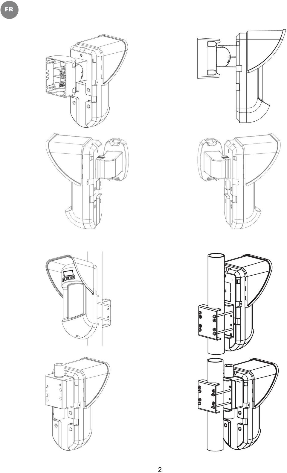
5 EN Wall Mount Installation Note: The installation knockouts numbering are marked on the back plate. Figure 1 Figure 2 I1 1. Open the Wireless PIR Outdoor Detector front cover (unlock C1, Figure 1). 2. Release internal base (unlock I1, Figure 2). 3. Select mounting installation as follows: Flat Mounting: Open knockouts on external base (Figure 3). B1 - B4: Wall mounting knockouts T1: Back tamper knockout 45 angle Mounting (Left side mounting): a. Open knockouts on external base (Figure 3). L1, L2: Left mounting knockouts T3: Left tamper knockout b. Remove tamper spring (Figure 4). c. Replace tamper bracket (Item 1) with supplied flat tamper bracket (Item 2). Figure 3 Tamper Lever B C1 T1 T3 L1 B1 W5 W6 T6 T5 T4 T2 R1 (not visible) B2 Item 1 Item 2 A W3 W9 W2 d. Insert Tamper lever B onto T6 and T3 and secure screw A (Figure 3). 4. Secure external base to the wall. 5. Insert tamper wires through internal base (Figure 4). 6. Secure internal base to external base (lock I1, Figure 2). Figure 4 L2 B4 R2 (not visible) B3 7. Close the front cover (Lock C1, Figure 1) after wiring and setting DIP switches. 8. Walk test the detector. Note: For 45 right side installation use the equivalent units on the external base as follows: Knockouts Description Left Right Mounting Knockouts L1, L2 R1, R2 Tamper spring knockouts T1,T3 T2,T4 Tamper screw anchor T5 T6 5
. c. Replace tamper bracket (Item 1) with supplied flat tamper bracket (Item 2).")
6 EN Changing Back Tamper position: The back tamper is by default secured on the right side of the internal base (Rear view). If you wish to move it to the left side (rear view), do the following (Figure 5): 1. Remove tamper screw 1 in order to release the tamper from position Ensure tamper spring (2) rests over tamper wire base Ensure plastic tamper bracket (3) rests over both 2 and Secure tamper screw (1) into (3) over position 6. Figure Left Side Tamper 6 4 Right Side Tamper 7 5 Notes: 1. Verify that you hear a "Click" when attaching the tamper spring to the wall. 2. For pole installation, the tamper can be moved to the bottom right-hand side of the internal base. 6

7 EN Back Tamper Terminal Wiring If you wish to use the back tamper (recommended) remove the short from the back tamper terminal block and connect the back tamper wires to the back tamper terminal block. BACK TAMPER Back Tamper in use H1 Back Tamper not used H1 Short Detection Range Adjustment Slide the moving PIR to the desired position, see figure 6. The range of the lower detection area determines the detection range. The upper PIR is fixed and its detection area is parallel to the ground at all times. The lower detection area changes from 2m to 12m depending on the location of the moving PIR. Therefore, the detection range is established according to the location of the lower PIR since both the upper and the lower PIR should be triggered in order to activate an alarm. Figure 6 7

8 EN Detection patterns (side view): Detection range with 1m (3'3") installation height: * Note: Length may vary according to environmental thermal conditions. Note: No effective detection occurs at distance less than 2.5 ft from the detector. Walk test Two minutes after applying power, walk test the protected area to verify proper operation. Adjust the moving PIR for required detection range and reliability. Important! Both upper and lower detection areas must be blocked simultaneously for detection to occur, see figure 7 below. Figure 7 8

9 EN LED Display LED State Description RED Steady Indicates ALARM Operational Modes Operational Mode Description Normal Dead time (between detection alarms) is 2.5 Minutes. Test (walk test) Dead time (between detection alarms) is 3 sec. Note: After power up the detector enters into test mode for a period of 20 minutes (disregarding the DIP Switch Modes Position). Transmitter/Receiver Communication link setup The detector must identify itself to the control panel s receiver by registering its coded message into the receiver s address memory. This is accomplished by performing the following steps: 1. Set the receiver to Registration Mode. 2. Remove the insulation material from the battery and place it in the battery holder on the PCB on the right direction (pay attention to the "+" and " " diagram on the PCB) 3. Send a registration message by closing both of the tamper switches (back and cover) for at least 3 seconds. 4. Verify that the detector has been identified by the receiver. Caution Notice Changes or modifications not expressly approved by Electronics Line may void the user s authority to operate this equipment. Simultaneous transmissions from two different units may cause message interference resulting in loss of information. The communication quality of this unit may be affected by its surrounding environment. Nearby electrical equipment may interfere with its normal operation. The operation of this unit must, therefore, be tested at each installation since its transmission quality may vary as a result of operational conditions. Optional Swivel Installation (Not Supplied) Please follow the instructions below for mounting the detector with the Swivel: 1. Open the Wireless PIR Outdoor Detector front cover (Unlock C1, Figure 1). 2. Release internal base (Unlock I1, Figure 2). 3. Remove back tamper from the internal base (see the Changing Back Tamper Position" paragraph on page Error! Bookmark not defined.) and connect it to S5 (Figure 8, Detail A) on the Standard Swivel. 4. Select the mounting installation as follows: Note: The swivel mount has not been evaluated by UL Ensure that you see the engraved UP mark on the upper front face of the swivel. Wall Mounting 1. Insert back tamper wires through the Swivel Wires Passage (Figure 8, Detail B). 2. Secure swivel to the wall through holes S1, S3, S6 and S8. 9

10 EN Detail A Standard Swivel S1 S2 W1 Detail B Snaps S8 S6 S4 S5 Tamper (see Detail C) S1 S2 S3 Detail C Figure 8 3. Connect the external base to the swivel using the dedicated snaps (Figure 9). See Detail A External Base Snaps Swivel to External Base Connecting Screws W1 Internal Base S1 S2 S3 Detail A Angle Locking Screw (See Note 2) PCB Swivel Assy Connecting Screw (See Note) Figure 9 Note: Do not open or close the Swivel Assy Screw since it is used for connecting the swivel parts only (factory tightened). 4. Secure external base to swivel with two screws fastened trough knockouts S1 and S2 (Figure 9). 10
 Figure 9 Note: Do not open or close the Swivel Assy Screw since it is used for connecting the swivel parts only (factory")
11 EN 5. Insert the supplied angle locking screw from the external base through the angle locking screw knockout S3 on the external base to the standard swivel (Figure 9). 6. Rotate the Standard Swivel to the desired position. Once the Standard Swivel is in the desired position, secure the angle locking screw. Important! Take care not to tilt the detector upwards and downwards. The detector should remain perpendicular to the ground for maximum detection and reliability. 7. Line up the internal base onto the external base. Insert tamper wiring through the internal base. 8. Secure internal base to external base (Lock I1, Figure 2). 9. To readjust the Standard Swivel when the PCB is installed (Figure 10): a. Bend down the black foam located below the RED LED on the PCB (enough to reach the Swivel locking screw). b. Use a Hex screwdriver to release the locking screw (see Figure 10). c. Rotate the Swivel to the desired position. d. Secure the angle locking screw. Figure 10: PCB Note: When marks on the two movable parts are aligned (Figure 9), the Standard Swivel is in 0 vertical/horizontal position. Each click from this position represents shifting of 5 in vertical/horizontal position. 10. Close the front cover (Lock C1, Figure 1) and walk test the detector. Note: The screw has to pass through the External Base and locked to the swivel. Replacing Lenses 1. Unlock the six screws that hold the lens holding sleeve from the back of the front cover. 2. To release the protective sleeve, gently push the lens from the external side of the front cover. 3. Disconnect the lens from the sleeve by gently pushing the lens clips that secure it to the sleeve. 4. Replace the lens. Place the 4 clips of the lens into the matching holes on the sleeve. 5. Insert the protective sleeve back into place on the front cover. Pay attention to place the sleeve over the sealing rubber. 6. Secure the 6 holding screws back to their place. 11
. 9.")
12 EN Sleeve Locking Screws Lens Locking Clips Lens Protecting Sleeve Sealing Rubber Sockets for Lens Clips. Front Cover Locking Screw Figure 11 12

13 EN Technical Specification Electrical Current consumption 20uA at 3 VDC (average) (standby) Current consumption 43mA at 3 VDC (Max. with LED OFF) (Alarm transmission) 53mA at 3 VDC (Max. with LED ON) Dead time (Normal Mode) 2.5 minutes Battery life 3 years (upon usage) Supervision transmission Every 10 minutes Range 300m (1000 feet) Line of Sight Battery 2 x CR123A 3VDC Lithium Battery * Use only the following CR123A batteries: DURACELL DL123A, GP GPCR123A, PANASONIC CR123A, SANYO CR123A, VARTA CR123A, EVE Energy CR123A Frequency / MHz Physical Size (LxWxD) 230 x 121 x 123mm (9 x 4.76 x 4.85 in.) Environmental Operating/Storage -25 C to 60 C (-13 F to 140 F) temperature * PIR technology is limited in harsh environmental conditions. RF immunity According to EN * Specifications are subject to change without prior notice. Ordering Information Model Description E8US248WXP0A EL Way Wireless Outdoor PIR 868 E4US248WXP0A EL Way Wireless Outdoor PIR 433 Accessory Kits Model Description Weight RA300S00000A Standard Swivel Kit 0.21 Kg (0.46 lb) RA300P Pole Adaptor Kit 0.25 Kg (0.55 lb) RTTE Compliance Statement Hereby, Electronics Line declares that this equipment is in compliance with the essential requirements and other relevant provisions of Directive 1999/5/EC. For the CE Declaration of Conformity please refer to our website: 13
 230 x 121 x 123mm (9 x 4.76 x 4.85 in.")
14 EN 14

15 FR Détecteur Extérieur Radio Modèle : EL-4800 Manuel d installation 1

16 FR 2
17 FR Introduction Le détecteur EL4800 est compatible avec les gammes I-Connect.2-way Veuillez suivre les instructions citées ci-dessous pour le choix de l'emplacement Choisir un emplacement 1. Hauteur d'installation: 0.8m à 1.2m max Hauteur d'installation recommandé: 1 m 2. TAfin d'assurer une fiabilité maximale, installez le détecteur perpendiculaire au sol de sorte que la zone de détection supérieure soit parallèle au sol. 3. Pour une détection optimale, choisissez un emplacement qui est susceptible de détecter un intrus se déplaçant à travers la zone de détection du radar. 4. Assurez-vous qu'aucun obstacle se trouve dans le champs de detection de la zone à protéger. 5. Ne dirigez pas le détecteur vers des objets susceptibles d'être en mouvement (avec le vent arbres, buissons ou une route). 3

18 FR Installation Détecteur extérieur EL4800 en situations difficiles Dans les situations suivantes, les variations de rayonnement infrarouge rapides et importantes peuvent se produire, ce qui entraîne de fausses alarmes 1. Les situations dans lesquelles des objets métalliques et / ou en verre mesurant plus de 70cm de hauteur à partir du sol sont dans le champ de vision du détecteur (voitures, des portes métalliques, volets, parois métalliques, fenêtres, etc.) 2. Les situations dans lesquelles une surface réfléchissante dans le champ de détection de plus de 1 m de diamètre peut provoquer la réflexion dans l'objectif du détecteur. Des exemples d'une surface réfléchissante dans le champ de détection sont : une flaque d'eau, route ou parking mouillée, béton lisse ou une surface asphaltée, piscine, etc. Water Reflection Note: 1. Veuillez noter que n'importe quel détecteur infrarouge en extérieur, devra avoir une portée inférieure aux éléments pouvant créer de fausse alarme comme : une voiture, un objet métallique ou une surface réfléchissante (de sorte que ces objets ne seront pas protégés) afin d'éliminer les fausses alarmes. 2. Pour 15m de pleine protection dans les situations ci-dessus, il est fortement recommandé d'installer le détecteur extérieur filaire. 3. Le détecteur inclut des filtres de silicium de haute qualité sur les capteurs pour bloquer les interférences lumineuses blanches. Ces filtres ne sont pas destinés à bloquer le rayonnement infrarouge thermique dû au soleil. Fixation murale Fixation 1. Ouvrez le capot avant du détecteur (déverrouillage C1, figure 1). 2. Ouvrir le détecteur (déverrouillage I1, Figure 2). 3. Sélectionner un des montages suivants : Montage à plat: Utilisez les préperçages présents sur la base du détecteur. Vissez la base à l'aide des trous de fixation B1-B2-B3-B4 (Figure 3). Mettre une vis à l'aide des trous de fixation pour autoprotection en T1 (Figure 3). Figure 1 C1 Figure 2 I1 4
 2.")
19 FR Montage à dans un angles à 45 (montage gauche): Utilisez les préperçages présent sur la base du détecteur. Vissez la base à l'aide des trous de fixation L1-L2-R1-R2 (Figure 3). Mettre une vis à l'aide des trous de fixation pour autoprotection en T3 (Figure 3). Supprimer le ressort du contact autoprotection Remplacer le support de contact autoprotection (ITEM1) avec le support plat (ITEM2) Figure 3 Tamper Lever B A T1 T3 L1 B1 W5 W6 W3 L2 B4 T6 T5 T4 T2 R1 (not visible) B2 W9 W2 R2 (not visible) B3 Item 1 Item 1 Insérez la languette (repère B) en T5 et T3 puis visser la vis (repère A Figure 3). Fixer la base intérieure sur la base extérieure à l aide de la vis L1 (Figure 2). Effectuer les réglages de l électronique du radar à l aide des micros interrupteur. Fermer le capot du Détecteur l aide de la vis C1 (Figure 1). Effectuer un test de passage pour vérifier le fonctionnement du détecteur Figure 4 Description des pré-perçages Gauche Droite Vis montage murale L1, L2 ou B1, B4 R1, R2ou B2, B3 Vis autoprotection T1, T3 T2,T4 Vis pour autoprotection à 45 T5 T6 5
 B2 W9 W2 R2 (not visible) B3 Item 1 Item 1 Insérez la languette (repère B) en T5 et T3 puis visser la vis (repère A Figure 3).")
20 FR Changer la position du contact autoprotection à arrachement: L'autoprotection est fixée sur le côté droit de la base interne (vue de dos). Si vous souhaitez déplacer sur la gauche (vue arrière), procédez de la façon suivante (Figure 5) : 1. Retirer altérer vis 1 afin de libérer l'autoprotection 2. Assurez que le ressort 2 repose sur le contact de l'autoprotection Assurer vous que le support de protection en plastique guide à la fois le 2 et le 4 Figure Left Side Tamper 6 Right Side Tamper 7 5 Si vous souhaitez utiliser l'autoprotection (recommandé) enlever le court à partir de la borne d'autoprotection et brancher les fils de retour à la borne d'autoprotection arrière. 2 BACK TAMPER Back Tamper in use H1 Back Tamper not used H1 SHUNT Short Réglage de la portée de détection Faites glisser la lentille pour passer à la position désirée sans mettre les doigts sur la lentille infrarouge, (voir figure 6). Figure 6 La plage de détection inférieure détermine la plage de détection du détecteur. La lentille supérieure est fixe et sa zone de détection est parallèle au sol à tout moment. La zone de détection inférieure détecte des mouvements de 2m à 12m en fonction de l'emplacement de la PIR mouvement. Par conséquent, la portée de détection est établi en fonction de l'emplacement de la lentille infrarouge inférieur puisque les deux (lentille haute et le basse) doit détecter afin d'activer une alarme. 6
")
21 FR Faisceaux des lentilles infrarouge (vue de coté) Distance de détection pour un détecteur installé à 1 m. Position Distance de détection Max. A 12m B 7m C 3m D 2m 7
22 FR Test de passage Deux minutes après la mise sous tension, testez la zone protégée avec un test de passage pour vérifier le bon fonctionnement. Important! Pour qu il y es un déclenchement les 2 faisceaux doivent être bloqué en même temps voire (figure 7 cidessous). Figure 7 LED Indication LED Etat Description Rouge Clignotement Indication alarme Mode opérationnel Mode opérationnel Description Normal Temps entre 2 détection 2.5min Test de passage Temps entre 2 détection 3s Important: Après avoir passer le détecteur en mode test de passage, après 20min le détecteur repasse en mode normal même si le micro interrupteur est sur mode test de passage. Enregistrement du détecteur Le détecteur doit être enregistré dans la centrale de la façon suivante suivantes: 1. Entrez dans le menu 9.Programmation, 1.Appareil, 1. Zone et validez une zone de libre. La centrale affiche «TRANSMISSION». 2. Retirez la languette de protection située entre la pile le contacteur. 3. Envoyer un message d'enregistrement en appuyant à une reprises sur les deux autoprotections (avant et arrière) pendant au moins 3 secondes. Un signal sonore vous confirmera la réception du signal à chaque fois. 4. La centrale affiche «ENREGISTRER?» Validez. 8
23 FR Important: Les changements ou modifications non approuvés par Electronics Line peuvent annuler le droit de l'utilisateur à utiliser cet équipement. Les Transmissions simultanées de deux unités différentes peuvent provoquer des interférences de message entraînant la perte de l'information. La qualité de la communication de cet appareil peut être affectée par son environnement. Les équipements électriques à proximité peuvent interférer avec son fonctionnement normal. Le fonctionnement de cet appareil doit donc être testé à chaque installation car sa qualité de transmission peut varier en raison des conditions environnementales. Montage mural par rotule (en option) Vous avez la possibilité d'installer le détecteur sur une rotule vendue en option afin de la faire pivoter. Suivez les instructions ci-dessous pour le montage du détecteur avec la rotule: 1. Ouvrez le capot avant du détecteur sans fil extérieur (devisé C1, figure 1). 2. Désolidarisé la base interne (devisé L1, Figure 2). 3. Retirer autoprotection à arrachement (voir la section " Changer la position du contact autoprotection à arrachement", page 7) et le fixer en S5 (Figure 8, détail A) sur la rotule standard. 4. Sélectionnez l'installation de montage comme suit: Note: Le support pivotant n'a pas été évaluée par UL Montage mural 1. Insérez les fils dans le Passage pour fils de la rotule pivotante (Figure 8, détail B). 2. Fixez la rotule pivotante au mur à travers les trous S1, S3, S6 et S8. Figure 8 Detail A Standard Swivel S1 S2 W1 Detail B Snaps S8 S6 S4 S5 Tamper (see Detail C) S1 S2 S3 Detail C 9
24 FR Figure 9 Note: Ne pas ouvrir ou fermer la vis Assy pivotant car il est utilisé pour relier les parties pivotantes seulement ( usine resserré ). 3. Visé la base externe avec deux vis S1 et S2 (Figure 9). 4. Insérer la vis de blocage d'angle fournie à partir de la base externe par l'intermédiaire des vis de verrouillage angle pré-perçage S3 sur la base extérieure ( figure 9). 5. Serrer la vis de blocage d'angle. 6. Rotate the Standard Swivel to the desired position. Once the Standard Swivel is in the desired position, secure the angle locking screw. Important: Veillez à ne pas incliner le détecteur vers le haut et vers le bas. Le détecteur doit rester perpendiculaire au sol pour une détection et une fiabilité maximum. 10
25 FR 7. Alignez la base interne sur la base externe. Insérez le câblage à travers la base interne. 8. Sécurisé la base interne à la base externe (Vis LI1, Figure 2). 9. Pour réajuster la rotule lorsque le circuit imprimer est installé (Figure 10) : a. Plier la mousse noir situé en dessous de la LED sur le PCB (suffisamment pour atteindre la vis de blocage de la rotule) b. Utilisez un tournevis cruciforme pour desserrer la vis de blocage ( voir figure 10) c. Tourner le pivot à la position désirée d. Serrez la vis de blocage angle. Figure 10 Note: Lorsque les deux marques sur les parties mobiles sont alignées (figure 9), la rotule standard est à 0 position verticale / horizontale. Chaque clic à partir de cette position consiste à passer de 5 en position verticale / horizontale. 10. Fermez le capot avant (Vis C1, figure 1) puis effectuer un test de passage. 11
26 FR Remplacement de la Lentille Comment remplacement les lentilles 1. Déverrouillez les six vis qui maintiennent la lentille. 2. Pour libérer la lentille de protection, poussez doucement la lentille du côté externe du capot. 3. Détachez l'objectif de la manche en poussant délicatement les clips de lentilles qui la fixent. 4. Placez les 4 clips de la lentille dans les trous correspondants. 5. Placer le support de lentille en place dans le capot avant. Faites attention à placer le manchon sur le joint en caoutchouc. Resserrer les 6 vis Figure 10 Lens Locking Clips Sleeve Locking Screws Sealing Rubber Lens Protecting Sleeve Sockets for Lens Clips Front Cover Locking Screw 12
27 FR Caractéristiques techniques Electrique Consommation de courant 20uA sous 3 VDC (repos) Consommation de courant 43mA sous 3 VDC (Max. avec LED OFF) (Transmission d alarme) 53mA sous 3 VDC (Max. avec LED ON) Temps économie énergie 2.5 minutes (Mode Normal) Durée batterie 3 ans (suivant usage) Supervision transmission Toutes les 10 minutes Distance 300m (en ligne droite sans obstacle avec la centrale Batterie 2 x CR123A 3VDC Batterie Lithium * Utilisé seulement les batteries CR123A suivantes: DURACELL DL123A, GP GPCR123A, PANASONIC CR123A, SANYO CR123A, VARTA CR123A, EVE Energy CR123A Fréquence / MHz Dimension Taille (Lxlxp) 230 x 121 x 123mm Environnement température -25 C to 60 C fonctionnement * La technologie infrarouge est limitée dans des conditions environnementales difficiles. Immunité RF EN * Specifications are subject to change without prior notice. Ordering Information Model Description E8US248WXP0A EL Way Wireless Outdoor PIR 868 E4US248WXP0A EL Way Wireless Outdoor PIR 433 Accessory Kits Model Description Weight RA300S00000A Standard Swivel Kit 0.21 Kg (0.46 lb) RA300P Pole Adaptor Kit 0.25 Kg (0.55 lb) 13
28 FR Electronics Line Limited Warranty EL and its subsidiaries and affiliates ("Seller") warrants its products to be free from defects in materials and workmanship under normal use for 24 months from the date of production. Because Seller does not install or connect the product and because the product may be used in conjunction with products not manufactured by the Seller, Seller can not guarantee the performance of the security system which uses this product. Sellers' obligation and liability under this warranty is expressly limited to repairing and replacing, at Sellers option, within a reasonable time after the date of delivery, any product not meeting the specifications. Seller makes no other warranty, expressed or implied, and makes no warranty of merchantability or of fitness for any particular purpose. In no case shall seller be liable for any consequential or incidental damages for breach of this or any other warranty, expressed or implied, or upon any other basis of liability whatsoever. Sellers obligation under this warranty shall not include any transportation charges or costs of installation or any liability for direct, indirect, or not be compromised or circumvented; that the product will prevent any persona; injury or property loss by intruder, robbery, fire or otherwise; or that the product will in all cases provide adequate warning or protection. Buyer understands that a properly installed and maintained alarm may only reduce the risk of intruder, robbery or fire without warning, but is not insurance or a guaranty that such will not occur or that there will be no personal injury or property loss as a result. Consequently seller shall have no liability for any personal injury, property damage or loss based on a claim that the product fails to give warning. However, if seller is held liable, whether directly or indirectly, for any loss or damage arising from under this limited warranty or otherwise, regardless of cause or origin, sellers maximum liability shall not exceed the purchase price of the product, which shall be complete and exclusive remedy against seller. No employee or representative of Seller is authorized to change this warranty in any way or grant any other warranty. WARNING: This product should be tested at least once a week. CAUTION: Risk of explosion if battery is replaced by an incorrect type. Dispose of used batteries according to local regulations. Contacting Electronics Line International Headquarters: Electronics Line 14 Hachoma St., Rishon Le Zion, Israel Tel: (+972-3) Fax: (+972-3) All rights reserved. No part of this document may be reproduced in any form without prior written permission from the publisher Electronics Line 3000 Ltd. 12/2013 5IN1859 B 14
Lavatory Faucet. Instruction Manual. Questions? 1-866-661-9606 customerservice@artikaworld.com
 Lavatory Faucet Instruction Manual rev. 19-01-2015 Installation Manual You will need Adjustable Wrench Adjustable Pliers Plumber s Tape Hardware list (included) Allen Key Socket wrench tool Important Follow
Folio Case User s Guide
 Fujitsu America, Inc. Folio Case User s Guide I N S T R U C T I O N S This Folio Case is a stylish, lightweight case for protecting your Tablet PC. Elastic Strap Pen Holder Card Holders/ Easel Stops Figure
WIRELESS SUPERVISED PHOTOELECTRIC SMOKE DETECTOR DÉTECTEUR DE FUMÉE PHOTOÉLECTRIQUE SUPERVISÉ SANS FILS. Model: EL-2703 INSTRUCTIONS D INSTALLATION
 WIRELESS SUPERVISED PHOTOELECTRIC SMOKE DETECTOR DÉTECTEUR DE FUMÉE PHOTOÉLECTRIQUE SUPERVISÉ SANS FILS Model: EL-2703 INSTRUCTIONS D INSTALLATION DÉTECTEUR DE FUMÉE PHOTOÉLECTRIQUE SUPERVISÉ SANS FILS
Warning: Failure to follow these warnings could result in property damage, or personal injury.
 Western Steel & Tube 1 Storage Locker Extended Storage Locker Storage Cabinet Assembly And Use Instructions Warning: Failure to follow these warnings could result in property damage, or personal injury.
ASSEMBLY INSTRUCTIONS DIRECTIVES POUR L'ASSEMBLAGE luster chandelier lamp chandelier à trois branches en verre lustré
 ASSEMBLY INSTRUCTIONS DIRECTIVES POUR L'ASSEMBLAGE luster chandelier lamp chandelier à trois branches en verre lustré SKU 2711592 INSTRUCTIONAL MANUAL MANUEL D'INSTRUCTIONS 270/2707 COMPONENT LIST LISTE
ASSEMBLY INSTRUCTIONS DIRECTIVES POUR L'ASSEMBLAGE ombre pendant lamp lampe suspendue à tons dégradés, chocolat
 ASSEMBLY INSTRUCTIONS DIRECTIVES POUR L'ASSEMBLAGE ombre pendant lamp lampe suspendue à tons dégradés, chocolat SKU 2728089 INSTRUCTIONAL MANUAL MANUEL D'INSTRUCTIONS 270/2707 COMPONENT LIST LISTE DES
R.V. Table Mounting Instructions
 PTSS165 ACCESSORY MOUNTING INSTRUCTIONS Use these instructions in conjunction with your main manual to properly assemble your gas grill. Refer to the main manual for safety, operating, cleaning and maintenance
Le No.1 de l économie d énergie pour patinoires.
 Le No.1 de l économie d énergie pour patinoires. Partner of REALice system Economie d énergie et une meilleure qualité de glace La 2ème génération améliorée du système REALice bien connu, est livré en
Notice Technique / Technical Manual
 Contrôle d accès Access control Encodeur USB Mifare ENCOD-USB-AI Notice Technique / Technical Manual SOMMAIRE p.2/10 Sommaire Remerciements... 3 Informations et recommandations... 4 Caractéristiques techniques...
03/2013. Mod: WOKI-60IP/TR. Production code: DTWIC 6000
 03/2013 Mod: WOKI-60IP/TR Production code: DTWIC 6000 ENCASTRABLE INDUCTION DROP IN INDUCTION 11/2011 TECHNICAL FEATURES DOCUMENTATION S.A.V. Notice d utilisation : FX00326-A Guide d intervention : ---
Garage Door Monitor Model 829LM
 Garage Door Monitor Model 829LM To prevent possible SERIOUS INJURY or DEATH from a closing garage door: NEVER permit children to operate or play with door control push buttons or remote control transmitters.
Contrôle d'accès Access control. Notice technique / Technical Manual
 p.1/18 Contrôle d'accès Access control INFX V2-AI Notice technique / Technical Manual p.2/18 Sommaire / Contents Remerciements... 3 Informations et recommandations... 4 Caractéristiques techniques... 5
Thank you for choosing the Mobile Broadband USB Stick. With your USB Stick, you can access a wireless network at high speed.
 Thank you for choosing the Mobile Broadband USB Stick. With your USB Stick, you can access a wireless network at high speed. Note: This manual describes the appearance of the USB Stick, as well as the
Fabricant. 2 terminals
 Specifications Fabricant Nominal torque (Nm) 65 Minimal torque (Nm) 0,63 Coil resistance - 20 C (ohms) 20 Rated current DC (A) 1 Rotor inertia (kg.m 2 ) 2.10-3 Weight (kg) 7,20 Heat dissipation continuous
GIGABIT PCI DESKTOP ADAPTER DGE-530T. Quick Installation Guide+ Guide d installation+
 GIGABIT PCI DESKTOP ADAPTER Quick Installation Guide+ Guide d installation+ Check Your Package Contents Quick Installation Guide Gigabit Ethernet PCI Adapter CD with Manual and Drivers DO NOT insert the
Package Contents. System Requirements. Before You Begin
 Package Contents DWA-125 Wireless 150 USB Adapter CD-ROM (contains software, drivers, and manual) Cradle If any of the above items are missing, please contact your reseller. System Requirements A computer
Instructions Mozilla Thunderbird Page 1
 Instructions Mozilla Thunderbird Page 1 Instructions Mozilla Thunderbird Ce manuel est écrit pour les utilisateurs qui font déjà configurer un compte de courrier électronique dans Mozilla Thunderbird et
Logitech Tablet Keyboard for Windows 8, Windows RT and Android 3.0+ Setup Guide Guide d installation
 Logitech Tablet Keyboard for Windows 8, Windows RT and Android 3.0+ Setup Guide Guide d installation English.......................................... 3 Français.........................................
Z-Axis Compliance Device Compliance en z
 Compensation for different vertical positions Collision recognition in Z-direction Protection of parts and work pieces Monitoring of the insertion forces during assembly operations Monitoring of the picking
SERVEUR DÉDIÉ DOCUMENTATION
 SERVEUR DÉDIÉ DOCUMENTATION Release 5.0.6.0 19 Juillet 2013 Copyright 2013 GIANTS Software GmbH, All Rights Reserved. 1/9 CHANGE LOG Correction de bug divers (5.0.6.0) Ajout d une option de relance automatique
PARIS ROISSY CHARLES DE GAULLE
 GPS 2 34 1 E 49 0 46 N GPS* 2 56 56 E 49 0 12 N Votre contact / Your contact: et / and: Accueil : Cabines téléphoniques publiques Reception: Public telephone kiosks Navette Shuttle AÉROPORT DE TT CAR TRANSIT
Règlement sur le télémarketing et les centres d'appel. Call Centres Telemarketing Sales Regulation
 THE CONSUMER PROTECTION ACT (C.C.S.M. c. C200) Call Centres Telemarketing Sales Regulation LOI SUR LA PROTECTION DU CONSOMMATEUR (c. C200 de la C.P.L.M.) Règlement sur le télémarketing et les centres d'appel
Guide d'installation rapide TFM-560X YO.13
 Guide d'installation rapide TFM-560X YO.13 Table of Contents Français 1 1. Avant de commencer 1 2. Procéder à l'installation 2 Troubleshooting 6 Version 06.08.2011 16. Select Install the software automatically
Manuel d'utilisation
 HUNTER-PRO 32 vers. 3 RXN-416 Manuel d'utilisation PIMA Electronic Systems Ltd. 5 Hatzoref Street, Holon 58856, Israël +972-3-5587722 +972-3-5500442 support@pima-alarms.com http://www.pima-alarms.com 2
Paxton. ins-20605. Net2 desktop reader USB
 Paxton ins-20605 Net2 desktop reader USB 1 3 2 4 1 2 Desktop Reader The desktop reader is designed to sit next to the PC. It is used for adding tokens to a Net2 system and also for identifying lost cards.
How to Login to Career Page
 How to Login to Career Page BASF Canada July 2013 To view this instruction manual in French, please scroll down to page 16 1 Job Postings How to Login/Create your Profile/Sign Up for Job Posting Notifications
Thank you for choosing the Mobile Broadband USB Stick. With your USB Stick, you can access a wireless network at high speed.
 Thank you for choosing the Mobile Broadband USB Stick. With your USB Stick, you can access a wireless network at high speed. Note: This manual describes the appearance of the USB Stick, as well as the
WINTER BOAT STORAGE SYSTEM SYSTÈME DE REMISAGE HIVERNAL POUR BATEAU
 MANUAL / MANUEL VIDEO WINTER BOAT STORAGE SYSTEM SYSTÈME DE REMISAGE HIVERNAL POUR BATEAU ASSEMBLY INSTRUCTIONS GUIDE D ASSEMBLAGE NAVIGLOO 14-18½ ft/pi FISHING BOAT! RUNABOUT! PONTOON BOAT! SAILBOAT (SAILBOAT
APPENDIX 2. Provisions to be included in the contract between the Provider and the. Holder
 Page 1 APPENDIX 2 Provisions to be included in the contract between the Provider and the Obligations and rights of the Applicant / Holder Holder 1. The Applicant or Licensee acknowledges that it has read
PRESENTATION REMOTE TÉLÉCOMMANDE DE PRÉSENTATION. User Guide Manuel de l utilisateur
 PRESENTATION REMOTE TÉLÉCOMMANDE DE PRÉSENTATION User Guide Manuel de l utilisateur Targus Presentation Remote Introduction Thank you for your purchase of the Targus Presentation Remote. This cordless
OUVRIR UN COMPTE CLIENT PRIVÉ
 OUVRIR UN COMPTE CLIENT PRIVÉ LISTE DE VERIFICATION Pour éviter tous retards dans le traitement de votre application pour l ouverture d un compte avec Oxford Markets ( OM, l Entreprise ) Veuillez suivre
First Nations Assessment Inspection Regulations. Règlement sur l inspection aux fins d évaluation foncière des premières nations CONSOLIDATION
 CANADA CONSOLIDATION CODIFICATION First Nations Assessment Inspection Regulations Règlement sur l inspection aux fins d évaluation foncière des premières nations SOR/2007-242 DORS/2007-242 Current to September
Monitor LRD. Table des matières
 Folio :1/6 Table des matières 1.Installation du logiciel... 3 2.Utilisation du logiciel... 3 2.1.Description de la fenêtre de commande... 3 2.1.1.Réglage des paramètres de communication... 4 2.1.2.Boutons
PAR RINOX INC BY RINOX INC PROGRAMME D INSTALLATEUR INSTALLER PROGRAM
 PAR RINOX INC BY RINOX INC PROGRAMME D INSTALLATEUR INSTALLER PROGRAM DEVENEZ UN RINOXPERT DÈS AUJOURD HUI! BECOME A RINOXPERT NOW OPTIMISER VOS VENTES INCREASE YOUR SALES VISIBILITÉ & AVANTAGES VISIBILITY
Instructions pour mettre à jour un HFFv2 v1.x.yy v2.0.00
 Instructions pour mettre à jour un HFFv2 v1.x.yy v2.0.00 HFFv2 1. OBJET L accroissement de la taille de code sur la version 2.0.00 a nécessité une évolution du mapping de la flash. La conséquence de ce
TABLE DES MATIERES A OBJET PROCEDURE DE CONNEXION
 1 12 rue Denis Papin 37300 JOUE LES TOURS Tel: 02.47.68.34.00 Fax: 02.47.68.35.48 www.herve consultants.net contacts@herve consultants.net TABLE DES MATIERES A Objet...1 B Les équipements et pré-requis...2
Nouveautés printemps 2013
 » English Se désinscrire de la liste Nouveautés printemps 2013 19 mars 2013 Dans ce Flash Info, vous trouverez une description des nouveautés et mises à jour des produits La Capitale pour le printemps
This is a preview - click here to buy the full publication NORME INTERNATIONALE INTERNATIONAL STAN DARD. Telecontrol equipment and systems
 NORME INTERNATIONALE INTERNATIONAL STAN DARD CEI IEC 870-3 Première édition First edition 1989-03 Matériels et systèmes de téléconduite Troisième partie: Interfaces (caractéristiques électriques) Telecontrol
Contents Windows 8.1... 2
 Workaround: Installation of IRIS Devices on Windows 8 Contents Windows 8.1... 2 English Français Windows 8... 13 English Français Windows 8.1 1. English Before installing an I.R.I.S. Device, we need to
Quick Installation Guide TEW-AO12O
 Quick Installation Guide TEW-AO12O Table of of Contents Contents Français... 1 1. Avant de commencer... 1 2. Installation du matériel... 2 3. Montage... 4 Troubleshooting... 6 Version 10.04.2007 1. Avant
POLICY: FREE MILK PROGRAM CODE: CS-4
 POLICY: FREE MILK PROGRAM CODE: CS-4 Origin: Authority: Reference(s): Community Services Department Cafeteria Services and Nutrition Education Division Resolution #86-02-26-15B.1 POLICY STATEMENT All elementary
Mesure chimique. Chemical measurement. Sonde de température Pt 1000 Inox Pt 1000 stainless steel. Ref : 703 262. Français p 1.
 Mesure chimique Chemical measurement Français p 1 English p 3 Sonde de température Pt 1000 Inox Pt 1000 stainless steel Version : 6010 Mesure chimique Sonde de température Pt 1000 Inox 1 Description La
The new consumables catalogue from Medisoft is now updated. Please discover this full overview of all our consumables available to you.
 General information 120426_CCD_EN_FR Dear Partner, The new consumables catalogue from Medisoft is now updated. Please discover this full overview of all our consumables available to you. To assist navigation
NORME INTERNATIONALE INTERNATIONAL STANDARD. Dispositifs à semiconducteurs Dispositifs discrets. Semiconductor devices Discrete devices
 NORME INTERNATIONALE INTERNATIONAL STANDARD CEI IEC 747-6-3 QC 750113 Première édition First edition 1993-11 Dispositifs à semiconducteurs Dispositifs discrets Partie 6: Thyristors Section trois Spécification
APPENDIX 6 BONUS RING FORMAT
 #4 EN FRANÇAIS CI-DESSOUS Preamble and Justification This motion is being presented to the membership as an alternative format for clubs to use to encourage increased entries, both in areas where the exhibitor
Le Cloud Computing est-il l ennemi de la Sécurité?
 Le Cloud Computing est-il l ennemi de la Sécurité? Eric DOMAGE Program manager IDC WE Security products & Solutions Copyright IDC. Reproduction is forbidden unless authorized. All rights reserved. Quelques
Frequently Asked Questions
 GS1 Canada-1WorldSync Partnership Frequently Asked Questions 1. What is the nature of the GS1 Canada-1WorldSync partnership? GS1 Canada has entered into a partnership agreement with 1WorldSync for the
Application Form/ Formulaire de demande
 Application Form/ Formulaire de demande Ecosystem Approaches to Health: Summer Workshop and Field school Approches écosystémiques de la santé: Atelier intensif et stage d été Please submit your application
Support Orders and Support Provisions (Banks and Authorized Foreign Banks) Regulations
 Regulations") CANADA CONSOLIDATION CODIFICATION Support Orders and Support Provisions (Banks and Authorized Foreign Banks) Regulations Règlement sur les ordonnances alimentaires et les dispositions alimentaires (banques
CANADA CONSOLIDATION CODIFICATION Support Orders and Support Provisions (Banks and Authorized Foreign Banks) Regulations Règlement sur les ordonnances alimentaires et les dispositions alimentaires (banques
3615 SELFIE. http://graffitiresearchlab.fr HOW-TO / GUIDE D'UTILISATION
 3615 SELFIE http://graffitiresearchlab.fr HOW-TO / GUIDE D'UTILISATION Hardware : Minitel Computer DIN FM545 45 connector (http://www.gotronic.fr/art-fiche-din-fm545-4747.htm) Cable Arduino compatible
Contrôle d accès Access control MOD-TCPIP-AI. Notice technique / Technical Manual
 Contrôle d accès Access control MOD-TCPIP-AI Notice technique / Technical Manual Notice technique Mod-TCPIP-AI 9 septembre 2008 v.1.0 p.2/16 Sommaire / Contents Sommaire / Contents...2 Remerciements...3
Spécial Catégorie 6 Patch Cords
 Spécial Catégorie 6 Patch Cords Patent Pending Sommaire 1 - Préliminaires... 2 2 Qu est ce qu apporte la catégorie 6... 3 3 Qu est ce que l interopérabilité...3 4 Ce que PatchSee annonçait en septembre
Stainless Steel Solar Wall Light
 V 2.9 Stainless Steel Solar Wall Light User Manual Please read and understand all instructions before use.retain this manual for future reference. V 2.9 Stainless Steel Solar Wall Light SPECIFICATIONS
GASKET FOR TONER COLLECTION BOTTLE
 Technical Service Bulletin PRODUCT CREATED DATE MODIFIED DATE FILE ALL PRINTERS 08/07/2011 201108 REV A GASKET FOR TONER COLLECTION BOTTLE Voir version française dans la section suivante. Due to a manufacturing
CALCUL DE LA CONTRIBUTION - FONDS VERT Budget 2008/2009
 Société en commandite Gaz Métro CALCUL DE LA CONTRIBUTION - FONDS VERT Budget 2008/2009 Taux de la contribution au Fonds vert au 1 er janvier 2009 Description Volume Coûts Taux 10³m³ 000 $ /m³ (1) (2)
JUPITER /20/27/61m. Contact NF, 50mA à 24v max. avec R50 Ohms en série
 JUPITER /20/27/61m 1 ) - SPECIFICATIONS TECHNIQUES Tension 12v nominal (8,5 à 16 v dc) Courant 25 ma max à 12vdc Ondulation 2v c/c à 12vdc Sortie alarme Contact NF, 50mA à 24v max. avec R50 Ohms en série
Guide d installation Deco Drain inc. DD200
 Guide d installation Deco Drain inc. DD200 Pour plus informations et pour télécharger les guides d installation en couleur, visitez notre site web. www.decodrain.com Soutien technique : Composez le : 514-946-8901
22/09/2014 sur la base de 55,03 euros par action
 CORPORATE EVENT NOTICE: Amortissement d'orane Reprise de cotation PUBLICIS GROUPE S.A. PLACE: Paris AVIS N : PAR_20140902_06559_EUR DATE: 02/09/2014 MARCHE: EURONEXT PARIS Amortissement en titres et en
Practice Direction. Class Proceedings
 Effective Date: 2010/07/01 Number: PD - 5 Title: Practice Direction Class Proceedings Summary: This Practice Direction describes the procedure for requesting the assignment of a judge in a proceeding under
DOCUMENTATION - FRANCAIS... 2
 DOCUMENTATION MODULE SHOPDECORATION MODULE PRESTASHOP CREE PAR PRESTACREA INDEX : DOCUMENTATION - FRANCAIS... 2 INSTALLATION... 2 Installation automatique... 2 Installation manuelle... 2 Résolution des
Multiple issuers. La cotation des actions ROBECO ci-dessous est suspendue sur EURONEXT PARIS dans les conditions suivantes :
 CORPORATE EVENT NOTICE: Suspension de cotation Multiple issuers PLACE: Paris AVIS N : PAR_20141002_07393_EUR DATE: 02/10/2014 MARCHE: EURONEXT PARIS La cotation des fonds mentionnés ci-dessous sera suspendue
NOTICE D UTILISATION
 GSM / SMS Scannez ce QR code ou rendez vous à l adresse web : http://www.fujionkyo.fr/produit/ kit-alarme-sans-fil-gsm-f3/ pour accéder à la notice vidéo du kit d alarme NFO-480030-1307 NOTICE D UTILISATION
FORMULAIRE D OUVERTURE DE COMPTE ENTREPRISE
 FORMULAIRE D OUVERTURE DE COMPTE ENTREPRISE LISTE DE VERIFICATION Pour éviter tous retards dans le traitement de votre application pour l ouverture d un compte avec Oxford Markets ( OM, l Entreprise )
Astra Elite AM/3 Manuel d'installation
 1) Caractéristiques techniques Astra Elite AM/3 Manuel d'installation Alimentation : - Tension : 9 à 16 V- - Consommation : 33 ma repos/40 ma en alarme - Ondulation : 2 V c à c à 12 V- Canal Hyperfréquence
English Q&A #1 Braille Services Requirement PPTC 144918. Q1. Would you like our proposal to be shipped or do you prefer an electronic submission?
 English Q&A #1 Braille Services Requirement PPTC 144918 Q1. Would you like our proposal to be shipped or do you prefer an electronic submission? A1. Passport Canada requests that bidders provide their
Cheque Holding Policy Disclosure (Banks) Regulations. Règlement sur la communication de la politique de retenue de chèques (banques) CONSOLIDATION
 Regulations. Règlement sur la communication de la politique de retenue de chèques (banques) CONSOLIDATION") CANADA CONSOLIDATION CODIFICATION Cheque Holding Policy Disclosure (Banks) Regulations Règlement sur la communication de la politique de retenue de chèques (banques) SOR/2002-39 DORS/2002-39 Current to
CANADA CONSOLIDATION CODIFICATION Cheque Holding Policy Disclosure (Banks) Regulations Règlement sur la communication de la politique de retenue de chèques (banques) SOR/2002-39 DORS/2002-39 Current to
AND / ET USER GUIDE UK HARDWIRED CONTROL PANEL UK GUIDE UTILISATEUR CENTRALE D ALARME FILAIRE F 496572 1
 AND / ET UK USER GUIDE HARDWIRED CONTROL PANEL UK F GUIDE UTILISATEUR CENTRALE D ALARME FILAIRE 496572 1 English UK Operator Controls and Displays On both control panel and remote keypad the LEDs display
Système d alarme sans fil GSM / SMS / RFID. www.camshop.fr
 Système d alarme sans fil GSM / SMS / RFID Caractéristiques Panneau de contrôle Reconnait jusqu à 10 télécommandes Peut être connectée jusqu à 50 capteurs sans fil (contacts porte / fenêtre, radars ) Peut
Propriétés de la matière. Material properties. Sonde de pression Pressure probe. Ref : 242 013. Français p 1. English p 3.
 Propriétés de la matière Material properties Français p 1 English p 3 Sonde de pression Pressure probe Version : 6010 Propriétés de la matière Sonde de pression 1 Principe et description 1.1 Principe La
F1 Security Requirement Check List (SRCL)
") F1 Security Requirement Check List (SRCL) Liste de vérification des exigences relatives à la sécurité (LVERS) Cyber Protection Supply Arrangement (CPSA) Arrangement en matière d approvisionnement en cyberprotection
F1 Security Requirement Check List (SRCL) Liste de vérification des exigences relatives à la sécurité (LVERS) Cyber Protection Supply Arrangement (CPSA) Arrangement en matière d approvisionnement en cyberprotection
AUTOPORTE III Notice de pose
 AUTOPORTE III Notice de pose Vous avez acquis le système AUTOPORTE, nous vous en remercions. Veuillez lire attentivement cette notice, vous serez à même de faire fonctionner correctement ce système. FONCTIONNEMENT
Tutoriel de formation SurveyMonkey
 Tutoriel de formation SurveyMonkey SurveyMonkey est un service de sondage en ligne. SurveyMonkey vous permet de créer vos sondages rapidement et facilement. SurveyMonkey est disponible à l adresse suivante
INVESTMENT REGULATIONS R-090-2001 In force October 1, 2001. RÈGLEMENT SUR LES INVESTISSEMENTS R-090-2001 En vigueur le 1 er octobre 2001
 FINANCIAL ADMINISTRATION ACT INVESTMENT REGULATIONS R-090-2001 In force October 1, 2001 LOI SUR LA GESTION DES FINANCES PUBLIQUES RÈGLEMENT SUR LES INVESTISSEMENTS R-090-2001 En vigueur le 1 er octobre
Phone Manager Soutien de l'application OCTOBER 2014 DOCUMENT RELEASE 4.1 SOUTIEN DE L'APPLICATION
 Phone Manager Soutien de l'application OCTOBER 2014 DOCUMENT RELEASE 4.1 SOUTIEN DE L'APPLICATION Sage CRM NOTICE The information contained in this document is believed to be accurate in all respects but
PROJET DE LOI. An Act to Amend the Employment Standards Act. Loi modifiant la Loi sur les normes d emploi
 2nd Session, 57th Legislature New Brunswick 60-61 Elizabeth II, 2011-2012 2 e session, 57 e législature Nouveau-Brunswick 60-61 Elizabeth II, 2011-2012 BILL PROJET DE LOI 7 7 An Act to Amend the Employment
RULE 5 - SERVICE OF DOCUMENTS RÈGLE 5 SIGNIFICATION DE DOCUMENTS. Rule 5 / Règle 5
 RULE 5 - SERVICE OF DOCUMENTS General Rules for Manner of Service Notices of Application and Other Documents 5.01 (1) A notice of application or other document may be served personally, or by an alternative
ROTOLINE NOTICE DE POSE
 ROTOLINE NOTICE DE POSE Nous vous remercions d avoir choisi le Système ROTOLINE pour ouvrir votre portail. Veuillez lire attentivement cette notice, vous serez à même de faire fonctionner ce système correctement.
Software and Hardware Datasheet / Fiche technique du logiciel et du matériel
 Software and Hardware Datasheet / Fiche technique du logiciel et du matériel 1 System requirements Windows Windows 98, ME, 2000, XP, Vista 32/64, Seven 1 Ghz CPU 512 MB RAM 150 MB free disk space 1 CD
86 rue Julie, Ormstown, Quebec J0S 1K0
 Tel : (450) 829-4200 Fax : (450) 829-4204 Email : info@rout-am.com Contacts: Jean Côté jean@rout-am.com Jocelyn Côté jocelyn@rout-am.com Dispatch info@rout-am.com Phone: (450) 829-4200 Fax: (450) 829-4204
Archived Content. Contenu archivé
 ARCHIVED - Archiving Content ARCHIVÉE - Contenu archivé Archived Content Contenu archivé Information identified as archived is provided for reference, research or recordkeeping purposes. It is not subject
Form of Deeds Relating to Certain Successions of Cree and Naskapi Beneficiaries Regulations
 CANADA CONSOLIDATION CODIFICATION Form of Deeds Relating to Certain Successions of Cree and Naskapi Beneficiaries Regulations Règlement sur la forme des actes relatifs à certaines successions de bénéficiaires
NOTICE D UTILISATION
 RTC Scannez ce QR code ou rendez vous à l adresse web : http://www.fujionkyo.fr/produit/ kit-alarme-rtc-f8/ pour accéder à la notice vidéo du kit d alarme NFO-480008-1307 NOTICE D UTILISATION Sommaire
GASCOGNE PAR_20150827_06702_ALT DATE: 27/08/2015. Pour faire suite à l'avis PAR_20150827_06701_EUR I - ADMISSION D'ACTIONS PAR COTATION DIRECTE
 CORPORATE EVENT NOTICE: Admission par cotation directe GASCOGNE PLACE: Paris AVIS N : PAR_20150827_06702_ALT DATE: 27/08/2015 MARCHE: Alternext Paris Pour faire suite à l'avis PAR_20150827_06701_EUR I
SA-32 / SA-62 INSTRUCTION MANUAL - MANUEL D INSTRUCTIONS
 SA-32 / SA-62 INSTRUCTION MANUAL - MANUEL D INSTRUCTIONS 4 5 6 7 4 5 6 7 1. Telephone Paging Volume Control 1. Contrôle de volume Paging Téléphone 2. Microphone Volume Control 2. Contrôle volume du microphone
Laboratory accredited by the French Home Office (official gazette date February 5 th, 1959, modified) Valid five years from August 27 th, 2013
 Valid five years from August 27 th, 2013") CLASSIFICATION REPORT OF REACTION TO FIRE PERFORMANCE IN ACCORDANCE WITH THE EUROPEAN STANDARD EN 350-+A: 203 and in compliance with the French Home Office Regulation dated November 2 st, 2002 concerning
CLASSIFICATION REPORT OF REACTION TO FIRE PERFORMANCE IN ACCORDANCE WITH THE EUROPEAN STANDARD EN 350-+A: 203 and in compliance with the French Home Office Regulation dated November 2 st, 2002 concerning
THE LAW SOCIETY OF UPPER CANADA BY-LAW 19 [HANDLING OF MONEY AND OTHER PROPERTY] MOTION TO BE MOVED AT THE MEETING OF CONVOCATION ON JANUARY 24, 2002
![THE LAW SOCIETY OF UPPER CANADA BY-LAW 19 [HANDLING OF MONEY AND OTHER PROPERTY] MOTION TO BE MOVED AT THE MEETING OF CONVOCATION ON JANUARY 24, 2002](/thumbs/19/276456.jpg "THE LAW SOCIETY OF UPPER CANADA BY-LAW 19 [HANDLING OF MONEY AND OTHER PROPERTY] MOTION TO BE MOVED AT THE MEETING OF CONVOCATION ON JANUARY 24, 2002") 2-aes THE LAW SOCIETY OF UPPER CANADA BY-LAW 19 [HANDLING OF MONEY AND OTHER PROPERTY] MOTION TO BE MOVED AT THE MEETING OF CONVOCATION ON JANUARY 24, 2002 MOVED BY SECONDED BY THAT By-Law 19 [Handling
2-aes THE LAW SOCIETY OF UPPER CANADA BY-LAW 19 [HANDLING OF MONEY AND OTHER PROPERTY] MOTION TO BE MOVED AT THE MEETING OF CONVOCATION ON JANUARY 24, 2002 MOVED BY SECONDED BY THAT By-Law 19 [Handling
Free filter reminders! Sign up online at: santevia.com/filterease. need help? Contact Santevia! 1-866-943-9220 help@santevia.com.
 Free filter reminders! Sign up online at: need help? Contact Santevia! -866-9-90 help@santevia.com Shower Filter English about our santevia Shower Filter Prevent leaks This shower filter employs NMC leading
SYSTÈME JETS D AIR WISH WISH AIR JETS SYSTEM Système de massage à jets d air pour bains en polymère - Air jet massage system for polymer bathtubs
 SYSTME JETS D AIR WISH WISH AIR JETS SYSTEM Système de massage à jets d air pour bains en polymère - Air jet massage system for polymer bathtubs Manuel d installation - Installation manual 6835, RUE PICARD
AMENDMENT TO BILL 32 AMENDEMENT AU PROJET DE LOI 32
 THAT the proposed clause 6(1), as set out in Clause 6(1) of the Bill, be replaced with the following: Trustee to respond promptly 6(1) A trustee shall respond to a request as promptly as required in the
that the child(ren) was/were in need of protection under Part III of the Child and Family Services Act, and the court made an order on
 was/were in need of protection under Part III of the Child and Family Services Act, and the court made an order on") ONTARIO Court File Number at (Name of court) Court office address Applicant(s) (In most cases, the applicant will be a children s aid society.) Full legal name & address for service street & number, municipality,
ONTARIO Court File Number at (Name of court) Court office address Applicant(s) (In most cases, the applicant will be a children s aid society.) Full legal name & address for service street & number, municipality,
Once the installation is complete, you can delete the temporary Zip files..
 Sommaire Installation... 2 After the download... 2 From a CD... 2 Access codes... 2 DirectX Compatibility... 2 Using the program... 2 Structure... 4 Lier une structure à une autre... 4 Personnaliser une
Règlement relatif à l examen fait conformément à la Déclaration canadienne des droits. Canadian Bill of Rights Examination Regulations CODIFICATION
 CANADA CONSOLIDATION CODIFICATION Canadian Bill of Rights Examination Regulations Règlement relatif à l examen fait conformément à la Déclaration canadienne des droits C.R.C., c. 394 C.R.C., ch. 394 Current
MELTING POTES, LA SECTION INTERNATIONALE DU BELLASSO (Association étudiante de lʼensaparis-belleville) PRESENTE :
 PRESENTE :") MELTING POTES, LA SECTION INTERNATIONALE DU BELLASSO (Association étudiante de lʼensaparis-belleville) PRESENTE : Housing system est un service gratuit, qui vous propose de vous mettre en relation avec
MELTING POTES, LA SECTION INTERNATIONALE DU BELLASSO (Association étudiante de lʼensaparis-belleville) PRESENTE : Housing system est un service gratuit, qui vous propose de vous mettre en relation avec
ARP-090G / ARP-090K NOTICE D'EMPLOI INSTRUCTION MANUAL
 2 7 NOTICE D'EMPLOI INSTRUCTION MANUAL ARP-090G / ARP-090K Lire attentivement la notice avant d utiliser l appareil Before operating this product, please read user manual completely FRANCAIS EMPLACEMENT
Stratégie DataCenters Société Générale Enjeux, objectifs et rôle d un partenaire comme Data4
 Stratégie DataCenters Société Générale Enjeux, objectifs et rôle d un partenaire comme Data4 Stéphane MARCHINI Responsable Global des services DataCenters Espace Grande Arche Paris La Défense SG figures
Sécurité relative aux sièges auto et aux rehausseurs
 Sécurité relative aux sièges auto et aux rehausseurs Safety with Car Seats and Booster Seats Car crashes are the main cause of accidental death and serious injury of children. Correctly using a car or
Logitech Speaker System Z553 Setup Guide Guide d installation
 Logitech Speaker System Z553 Setup Guide Guide d installation Logitech Speaker System Z553 English................. 3 Français................ 10 www.logitech.com/support...19 2 Package contents Logitech
COPYRIGHT Danish Standards. NOT FOR COMMERCIAL USE OR REPRODUCTION. DS/EN 61303:1997
 COPYRIGHT Danish Standards. NOT FOR COMMERCIAL USE OR REPRODUCTION. DS/EN 61303:1997 COPYRIGHT Danish Standards. NOT FOR COMMERCIAL USE OR REPRODUCTION. DS/EN 61303:1997 COPYRIGHT Danish Standards. NOT
LOGICIEL D'ADMINISTRATION POUR E4000 & G4000 MANAGEMENT SOFTWARE FOR E4000 & G4000
 LOGICIEL D'ADMINISTRATION POUR E4000 & G4000 MANAGEMENT SOFTWARE FOR E4000 & G4000 TABLE DES MATIÈRES TITRE PAGE Présentation - - - - - - - - - - - - - - - - - - - - - - - - - - - - - - - - - - - -4 Le
SYSTÈME DE GAINES À SPIRALE ET RACCORDS TOURNANTS
 SYSTÈME DE GAINES À SPIRALE ET RACCORDS TOURNANTS SPIRAL PVC CONDUIT SYSTEMS AND REVOLVING FITTINGS Gaines a Spirale Matufless...page 190 Matufless spiral PVC conduit Raccords Tournants Matufless...page