Technical Manual. Nexus Smart Switch. This manual should remain with the unit.
|
|
|
- Côme Martin
- il y a 10 ans
- Total affichages :
Transcription
1 Technical Manual Nexus Smart Switch This manual should remain with the unit.

2 Safety Rules SAVE THESE INSTRUCTIONS! Read the following information carefully before attempting to install, operate or service this equipment. Also read the instructions and information on tags, decals, and labels that may be affixed to the transfer switch. Replace any decal or label that is no longer legible. DANGER! Connection of a generator to an electrical system normally supplied by an electric utility shall be by means of suitable transfer equipment so as to isolate the electric system from utility distribution system when the generator is operating (Article 701 Legally Required Standby Systems or Article 702 Optional Standby Systems, as applicable). Failure to isolate electric system by these means may result in damage to generator and may result in injury or death to utility workers due to backfeed of electrical energy. The manufacturer cannot anticipate every possible circumstance that might involve a hazard. The warnings in this manual, and on tags and decals affixed to the unit are, therefore, not all-inclusive. If using a procedure, work method or operating technique the manufacturer does not specifically recommend, ensure that it is safe for others. Also make sure the procedure, work method or operating technique chosen does not render the transfer switch unsafe. Throughout this publication, and on tags and decals affixed to the generator, DANGER, WARNING, CAUTION and NOTE blocks are used to alert personnel to special instructions about a particular operation that may be hazardous if performed incorrectly or carelessly. Observe them carefully. Their definitions are as follows: After this heading, read instructions that, if not strictly complied with, will result in serious personal injury, including death. After this heading, read instructions that, if not strictly complied with, could result in serious personal injury, including death. After this heading, read instructions that, if not strictly complied with, might result in minor or moderate injury. NOTE: After this heading, read instructions that, if not strictly complied with, may result in damage to equipment and/or property. These safety warnings cannot eliminate the hazards that they indicate. Common sense and strict compliance with the special instructions while performing the service are essential to preventing accidents. Four commonly used safety symbols accompany the DANGER, WARNING and CAUTION blocks. The type of information each indicates follows: This symbol points out important safety information that, if not followed, could endanger personal safety and/or property. This symbol points out potential explosion hazard. This symbol points out potential fire hazard. This symbol points out potential electrical shock hazard. GENERAL HAZARDS Any AC generator that is used for backup power if a NORMAL (UTILITY) power source failure occurs, must be isolated from the NORMAL (UTILITY) power source by means of an approved transfer switch. Failure to properly isolate the NORMAL and STANDBY power sources from each other may result in injury or death to electric utility workers, due to backfeed of electrical energy. Improper or unauthorized installation, operation, service or repair of the equipment is extremely dangerous and may result in death, serious personal injury, or damage to equipment and/ or personal property. Extremely high and dangerous power voltages are present inside an installed transfer switch. Any contact with high voltage terminals, contacts or wires will result in extremely hazardous, and possibly LETHAL, electric shock. DO NOT WORK ON THE TRANSFER SWITCH UNTIL ALL POWER VOLTAGE SUPPLIES TO THE SWITCH HAVE BEEN POSITIVELY TURNED OFF. Competent, qualified personnel should install, operate and service this equipment. Adhere strictly to local, state and national electrical and building codes. When using this equipment, comply with regulations the National Electrical Code (NEC), CSA Standard; C22.1 Canadian Electric Code and Occupational Safety and Health Administration (OSHA) have established. Never handle any kind of electrical device while standing in water, while barefoot, or while hands or feet are wet. DANGEROUS ELECTRICAL SHOCK MAY RESULT. Remove all jewelry (such as rings, watches, bracelets, etc.) before working on this equipment.
.")
3 Table of Contents If work must be done on this equipment while standing on metal or concrete, place insulative mats over a dry wood platform. Work on this equipment only while standing on such insulative mats. Never work on this equipment while physically or mentally fatigued. Keep the transfer switch enclosure door closed and bolted at all times. Only qualified personnel should be permitted access to the switch interior. In case of an accident caused by electric shock, immediately shut down the source of electrical power. If this is not possible, attempt to free the victim from the live conductor but AVOID DIRECT CONTACT WITH THE VICTIM. Use a nonconducting implement, such as a dry rope or board, to free the victim from the live conductor. If the victim is unconscious, apply first aid and get immediate medical help. When an automatic transfer switch is installed for a standby generator set, the generator engine may crank and start at any time without warning. To avoid possible injury that might be caused by such sudden start-ups, the system s automatic start circuit must be disabled before working on or around the generator or transfer switch. Then place a DO NOT OPERATE tag on the transfer switch and on the generator. Remove the Negative (Neg) or ( ) battery cable. Safety Rules... Inside Front Cover General Information Introduction Unpacking Equipment Description Transfer Switch Data Decal Transfer Switch Enclosure Safe Use Of Transfer Switch... 3 Installation Introduction to Installation Mounting Connecting Power Source and Load Lines Pole Mechanism Connecting Start Circuit Wires Connecting Load Shed Module (LSM) Connections Sequence of Operation... 4 Operation Functional Tests & Adjustments Manual Operation Close to Normal Source Side Close to Emergency Source Side Return to Normal Source Side Voltage Checks Generator Tests Under Load Testing Load Shed Module (LSM)... 8 Notes... 9 Installation Diagram Electrical Data Exploded Views & Parts Lists Manual técnico Manual technique For authorized service, reference the dealer locator number found inside the generator owner s manual. 1

4 General Information 1.1 INTRODUCTION This manual has been prepared especially for the purpose of familiarizing personnel with the design, application, installation, operation and servicing of the applicable equipment. Read the manual carefully and comply with all instructions. This will help to prevent accidents or damage to equipment that might otherwise be caused by carelessness, incorrect application, or improper procedures. Every effort has been expended to make sure that the contents of this manual are both accurate and current. The manufacturer, however, reserves the right to change, alter or otherwise improve the product at any time without prior notice. 1.2 UNPACKING Carefully unpack the transfer switch. Inspect closely for any damage that might have occurred during shipment. The purchaser must file with the carrier any claims for loss or damage incurred while in transit. Check that all packing material is completely removed from the switch prior to installation. 1.3 EQUIPMENT DESCRIPTION The automatic transfer switch is used for transferring critical electrical load from a UTILITY (NORMAL) power source to a GENERATOR (STANDBY) power source. Such a transfer of electrical loads occurs automatically when the UTILITY power source has failed or is substantially reduced and the GENERATOR source voltage and frequency have reached an acceptable level. The transfer switch prevents electrical feedback between two different power sources (such as the UTILITY and GENERATOR sources) and, for that reason, codes require it in all standby electric system installations. The transfer switch consists of a transfer mechanism, a relay control, a load shed controller, a terminal strip and fuse holder for connection of sensing wires. This switch is suitable for control of motors, electric discharge lamps, tungsten filament and electric heating equipment and the tungsten load does not exceed 30% of the switch rating. This UL listed transfer switch is for use in optional standby systems only (NEC article 702). A 100A rated switch is suitable for use on circuits capable of delivering not more than 10,000 RMS symetrical amperes, 250 VAC maximum, when protecty by a 100A maximum circuit breaker (Siemens types QP or BQ) or 150A maximum circuit breaker (Square D Q2, Westinghouse CA-CAH, General Electric TQ2 and Siemens QJ2). A 200A rated switch is suitable for use on a circuit capable of 10,000 rms symmetrical amperes, 240 VAC when protected by a circuit breaker without an adjustable short time response or by fuses. The Load Shed Module is designed to prevent an overload on the generator when it is supplying the customer loads. See figure 1.1. Up to six loads can be managed by the LSM; 2 air conditioner loads and 4 other loads. The LSM manages the loads by shedding the connected loads in the event of a drop in generator frequency (overload). Loads to be shed are grouped in 4 priority levels on the LSM. Priority 1 and 2 has connections for both one air conditioner and one contactor. Both an air conditioner and a contactor can be used at the same time if desired. To control an air conditioner, no additional equipment is required. Internal relays interrupt the thermostat 24VAC control signal to disable the air conditioner load. Priority 3 and 4 have connections for one contactor only. Four LEDs, located on the load shed module, will indicate when a load priority level is enabled. Any loads, including central air conditioners, can be controlled via a contactor that must be purchased separately. Up to four contactors can be controlled by the load shed module. The LSM supplies the 120 Vac to energize each contactor coil. Generator overload condition is determined by generator frequency. Loads are shed when the frequency is <58Hz for 3 seconds or <50Hz for ½ Second (For 60Hz). The LSM has a Test button which forces the unit to act as if an overload has occurred. This button operates even when the transfer signal is inactive. Air Conditioner Connections: Up to two A/Cs can be controlled via low voltage thermostat wires Figure 1.1 Load Shed Module Status LEDs: Shows which loads are currently allowed to run. 0 Ground V 23 Transfer T1 NEUTRAL AIR 1 CONTACTOR 1 AIR 2 CONTACTOR 2 Priority 1 CONTACTOR Priority 2 3 Priority 3 CONTACTOR 4 Priority 4 Load Connections: Up to four loads of any type can be controlled via these connections. (A separate contactor module is required.) 2

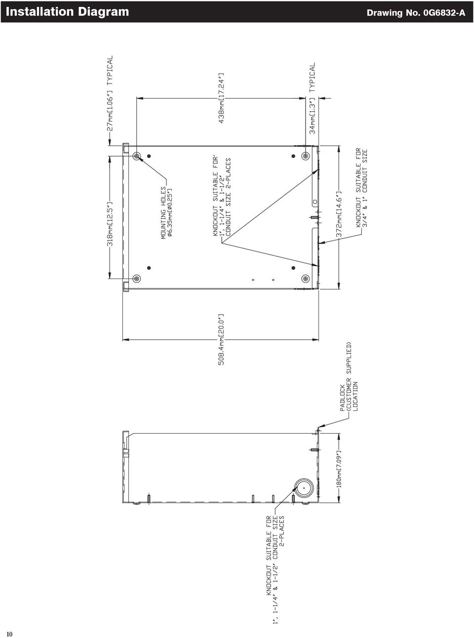
5 Installation 1.4 TRANSFER SWITCH DATA DECAL A DATA DECAL is permanently affixed to the transfer switch enclosure. Use this transfer switch only within the specific limits shown on the DATA DECAL and on other decals and labels that may be affixed to the switch. This will prevent damage to equipment and property. When requesting information or ordering parts for this equipment, make sure to include all information from the DATA DECAL. Record the Model and Serial numbers in the space provided below for future reference. MODEL # SERIAL # 1.5 TRANSFER SWITCH ENCLOSURE The standard switch enclosure is a National Electrical Manufacturer s Association (NEMA) and UL 3R type. UL and NEMA 3R type enclosures primarily provide a degree of protection against falling rain and sleet; is undamaged by the formation of ice on the enclosure. 1.6 SAFE USE OF TRANSFER SWITCH Before installing, operating or servicing this equipment, read the SAFETY RULES (inside front cover) carefully. Comply strictly with all SAFETY RULES to prevent accidents and/or damage to the equipment. The manufacturer recommends that a copy of the SAFETY RULES are posted near the transfer switch. Also, be sure to read all instructions and information found on tags, labels and decals affixed to the equipment. Two publications that outline the safe use of transfer switches are the following: NFPA 70; National Electrical Code UL 1008, STANDARD FOR SAFETY-AUTOMATIC TRANSFER SWITCHES NOTE: It is essential to use the latest version of any standard to ensure correct and current information. 2.1 INTRODUCTION TO INSTALLATION This equipment has been wired and tested at the factory. Installing the switch includes the following procedures: Mounting the enclosure. Connecting power source and load leads. Connecting the generator start and sensing circuit. Connecting any auxiliary contact (if needed) Connect load shed module loads (as required) Testing functions. 2.2 MOUNTING Mounting dimensions for the transfer switch enclosure are in this manual. Enclosures are typically wall-mounted. See the Installation Diagram section. Handle transfer switches carefully when installing. Do not drop the switch. Protect the switch against impact at all times, and against construction grit and metal chips. Never install a transfer switch that has been damaged. Install the transfer switch as close as possible to the electrical loads that are to be connected to it. Mount the switch vertically to a rigid supporting structure. To prevent switch distortion, level all mounting points. If necessary, use washers behind mounting holes to level the unit. 2.3 CONNECTING POWER SOURCE AND LOAD LINES Make sure to turn OFF both the UTILITY (NORMAL) and EMERGENCY (STANDBY) power supplies before trying to connect power source and load lines to the transfer switch. Supply voltages are extremely high and dangerous. Contact with such high voltage power supply lines will result in an extremely hazardous, possibly lethal, electrical shock. Wiring diagrams and electrical schematics are provided in this manual. Power source and load connections are made at a transfer mechanism, inside the switch enclosure POLE MECHANISM These switches (Figure 2.1) are used with a single-phase system, when the single-phase NEUTRAL line is to be connected to a Neutral Lug and is not to be switched. 3

6 Installation Figure 2.1 Typical 2-Pole Transfer Mechanism (200 Amp Shown) UTILITY CLOSING COIL GENERATOR CLOSING COIL UTILITY LUGS LOAD LUGS (T1 & T2) Solderless, screw-type terminal lugs are standard. Switch Rating Wire Range GENERATOR LUGS (E1 & E2) Conductor Tightening Torque 100A #14-1/0 AWG 50 in-lbs. 200A #6-250 MCM 275 in-lbs. Conductor sizes must be adequate to handle the maximum current to which they will be subjected to, based on the 75 C column of tables, charts, etc. used to size conductors. The installation must comply fully with all applicable codes, standards and regulations. Before connecting wiring cables to terminals, remove any surface oxides from the cable ends with a wire brush. All power cables should enter the switch next to transfer mechanism terminals. If ALUMINUM conductors are used, apply corrosion inhibitor to conductors. Tighten terminal lugs to the torque values as noted on the decal located on the inside of the door. After tightening terminal lugs, carefully wipe away any excess corrosion inhibitor. All power cables should enter the switch next to the transfer mechanism terminals. Use a torque wrench to tighten the conductors, being sure not to over tighten, or damage to the switch base could occur. If not tightened enough, a loose connection would result, causing excess heat which could damage the switch base. Connect power source load conductors to clearly marked transfer mechanism terminal lugs as follows: 1. Connect UTILITY (NORMAL) power source cables to switch terminals N1, N2. 2. Connect EMERGENCY (STANDBY) source power cables to transfer switch terminals E1, E2. 3. Connect customer LOAD leads to switch terminals T1, T2. Conductors must be properly supported, of approved insulative qualities, protected by approved conduit, and of the correct wire gauge size in accordance with applicable codes. Be sure to maintain proper electrical clearance between live metal parts and grounded metal. Allow at least 1/2 inch for amp circuits. 2.4 CONNECTING START CIRCUIT WIRES Control system interconnections (Electrical Data section) consist of UTILITY 1 (N1), UTILITY 2 (N2) and LOAD (T1), and leads 23 and 194. Recommended wire gauge sizes for this wiring depends on the length of the wire, as recommended in the following chart: MAXIMUM WIRE LENGTH RECOMMENDED WIRE SIZE 460 feet (140m) No. 18 AWG. 461 to 730 feet (223m) No. 16 AWG. 731 to 1,160 feet (354m) No. 14 AWG. 1,161 to 1,850 feet (565m) No. 12 AWG. 2.5 CONNECTING LOAD SHED MODULE (LSM) CONNECTIONS The LSM can control an air conditioner (24 Vac) directly or a separate contactor (120 Vac) which can control any load connected to it. See Figure SEQUENCE OF OPERATION The 4 green status LEDs will indicate when a load priority level is enabled. All loads are enabled when the transfer signal is off. (ATS in Utility position). If the transfer signal is pulled low (Active) All loads are enabled until an overload is detected When an overload is detected all loads are disabled After 5 minutes priority 1 loads are enabled. After another 30 seconds priority 2 loads are enabled After another 30 seconds priority 3 loads are enabled After another 30 seconds priority 4 loads are enabled If an overload is detected within 30 seconds of a level being enabled, all loads are disabled again and the sequence repeats. However, the level that caused the overload and all levels higher will not be enabled again for 30 minutes. 4

7 Installation Figure 2.2 Load Shed Module Connections Supply 0 Ground V Contactor #1 Load #1 Y wire 23 Transfer T1 AIR 1 NEUTRAL CONTACTOR Supply AIR 2 Priority 1 1 CONTACTOR 2 CONTACTOR Coil wires Contactor #2 Load #2 Priority 2 3 Supply Y wire Priority 3 Priority 4 CONTACTOR 4 Contactor #3 Load #3 Supply Contactor #4 Load #4 Control of Air Conditioner Load 1. Route the thermostat cable (from the furnace/thermostat to the outdoor air conditioner unit) to the transfer switch. 2. Connect the wire to the terminal strip terminals (Air 1) on the LSM as shown in Figure 2.2. These are normally closed contacts which open upon load shed conditions. Route thermostat wire away from High voltage wires. 3. If required, connect the second air conditioner to the terminal strip terminals (Air 2). Air 1 & 2 Contact Ratings 24 VAC, 5.0 Amps Max NOTE: These instructions are for a typical air conditioner installation. Control of heat pump and 2-stage air conditioners will require special connections. Control of a Separate Contactor A separate contactor relay module can be purchased from the manufacturer. If a different relay is used it must have a 120 Vac coil voltage. The LSM supplies fused (5A) 120 Vac to energize the coils of the relay contactors (contactor 1, 2, 3 or 4). 1. Mount the contactor module and connect the load to the main contacts. 2. Connect the contactor coil to the desired LSM (contactor 1, 2, 3 or 4) terminals on the terminal strip. 3. Connect additional load shedding contactors in a similar fashion. NOTE: It will be necessary to determine the order of shedding the connected loads and connect the loads to the LSM in that order. One is the highest priority and four is the lowest priority. 5
 to the transfer switch. 2.")
8 Operation 3.1 FUNCTIONAL TESTS AND ADJUSTMENTS Following transfer switch installation and interconnection, inspect the entire installation carefully. A competent, qualified electrician should inspect it. The installation should comply strictly with all applicable codes, standards, and regulations. When absolutely certain the installation is proper and correct, complete a functional test of the system. Perform functional tests in the exact order presented in this manual, or damage could be done to the switch. IMPORTANT: Before proceeding with functional tests, read and make sure all instructions and information in this section are understood. Also read the information and instructions of labels and decals affixed to the switch. Note any options or accessories that might be installed and review their operation. 3.2 MANUAL OPERATION Do NOT manually transfer under load. Disconnect transfer switch from all power sources by approved means, such as a main circuit breaker(s). A manual HANDLE is shipped with the transfer switch. Manual operation must be checked BEFORE the transfer switch is operated electrically. To check manual operation, proceed as follows: 1. Turn the generator s AUTO/OFF/MANUAL switch to OFF. 2. Turn OFF both UTILITY and EMERGENCY power supplies to the transfer switch, with whatever means provided (such as the main line circuit breakers). 3. Note position of transfer mechanism main contacts by observing the moveable contact carrier arm. Manual operation handle towards the top of switch mechanism - LOAD terminals (T1, T2) are connected to UTILITY terminals (N1, N2). Manual operation handle towards the bottom of switch mechanism - LOAD terminals (T1, T2) are connected to EMERGENCY terminals (E1, E2). Do not use excessive force when operating the transfer switch manually or damage could be done to the manual handle CLOSE TO NORMAL SOURCE SIDE Before proceeding, verify the position of the switch by observing the position of manual operation handle in Figure 3.1. If the handle is UP, the contacts are closed in the NORMAL position, no further action is required. If the handle is DOWN, proceed with Step 1. Step 1: With the handle inserted into the actuating shaft, move handle UP. Be sure to hold on to the handle as it will move quickly after the center of travel CLOSE TO EMERGENCY SOURCE SIDE Before proceeding, verify the position of the switch by observing the position of the manual operation handle in Figure 3.1. If the handle is DOWN, the contacts are closed in the EMERGENCY (STANDBY) position. No further action is required. If the handle is UP, proceed with Step 1. Step 1: With the handle inserted into the actuating shaft, move the handle DOWN. Be sure to hold on to the handle as it will move quickly after the center of travel RETURN TO NORMAL SOURCE SIDE Manually actuate switch to return manual operating handle to the UP position. 3.3 VOLTAGE CHECKS 1. Turn ON the UTILITY power supply to the transfer switch with whatever means provided (such as the UTILITY main line circuit breaker). PROCEED WITH CAUTION. THE TRANSFER SWITCH IS NOW ELECTRICALLY HOT. CONTACT WITH LIVE TERMINALS RESULTS IN EXTREMELY HAZARDOUS AND POSSIBLY FATAL ELECTRICAL SHOCK. 2. With an accurate AC voltmeter, check for correct voltage. Single-phase utility supply: Measure across ATS terminal lugs N1 and N2. Also check N1 to NEUTRAL and N2 to NEUTRAL. 3. When certain that UTILITY supply voltage is correct and compatible with transfer switch ratings, turn OFF the UTILITY supply to the transfer switch. 4. On the generator panel, set the AUTO/OFF/MANUAL switch to MANUAL position. The generator should crank and start. 5. Let the generator stabilize and warm up at no-load for at least five minutes. 6. Set the generator's main circuit breaker (CB1) to its ON or CLOSED position. 6

9 Operation Figure 3.1 Actuating Transfer Switch Attach handle to actuating shaft. NOTE: Return handle to storage position in enclosure when finished with manual transfer. Move handle UP for the NORMAL (UTILITY) position. Move handle DOWN for the EMERGENCY (STANDBY) position. PROCEED WITH CAUTION. GENERATOR OUTPUT VOLTAGE IS NOW BEING DELIVERED TO TRANSFER SWITCH TERMINALS. CONTACT WITH LIVE TERMINALS RESULTS IN EXTREMELY DANGEROUS AND POSSIBLY FATAL ELECTRICAL SHOCK. 7. With an accurate AC voltmeter and frequency meter, check the no-load, voltage and frequency. Single-phase generator supply: Measure across ATS terminal lugs E1 to E2. Also check E1 to NEUTRAL and E2 to NEUTRAL. a. Frequency Hertz b. Terminals E1 to E VAC c. Terminals E1 to NEUTRAL VAC d. Terminals E2 to NEUTRAL VAC 8. Set the generator s main circuit breaker (CB1) to its OFF or OPEN position. 9. Set the AUTO/OFF/MANUAL switch to the OFF position to shut down the generator. NOTE: Do NOT proceed until generator AC output voltage and frequency are correct and within stated limits. If the no-load voltage is correct but no-load frequency is incorrect, the engine governed speed probably requires adjustment. If no-load frequency is correct but voltage is not, the voltage regulator may require adjustment. 7

10 Operation 3.4 GENERATOR TESTS UNDER LOAD 1. Set the generator's main circuit breaker to its OFF or OPEN position. 2. Manually actuate the transfer switch main contacts to their EMERGENCY (STANDBY) position. Refer to the "Manual Operation" section. 3. To start the generator, set the AUTO/OFF/MANUAL switch to MANUAL. When engine starts, let it stabilize for a few minutes. 4. Turn the generator's main circuit breaker to its ON or CLOSED position. The generator now powers all LOAD circuits. Check generator operation under load as follows: Turn ON electrical loads to the full rated wattage/amperage capacity of the generator. DO NOT OVERLOAD. With maximum rated load applied, check voltage and frequency across transfer switch terminals E1 and E2. Voltage should be greater than 230 volts and frequency should be greater than 59 Hertz. Let the generator run under rated load for at least 30 min- utes. With unit running, listen for unusual noises, vibration, overheating, etc., that might indicate a problem. 5. When checkout under load is complete, set main circuit breaker of the generator to its OFF or OPEN position. 6. Let the generator run at no-load for several minutes. Then, shut down by setting the AUTO/OFF/MANUAL switch to its OFF position. 7. Move the switch's main contacts back to their UTILITY position. For example, load connected to UTILITY power supply. Refer to the "Manual Operation" section. Handle and operating lever of transfer switch should be in UP position. 8. Turn on the UTILITY power supply to transfer switch, using whatever means provided (such as a UTILITY main line circuit breaker). The UTILITY power source now powers the loads. 9. Set the generator's AUTO/OFF/MANUAL switch to its AUTO position. The system is now set for fully automatic operation. 3.5 TESTING LOAD SHED MODULE (LSM) A Test pushbutton is provided on the bottom of the LSM to test the operation of the tested functions. The Test button will work when the ATS is in the Utility or the Generator position. 1. Turn the Utility supply on to the ATS. 2. Press the TEST pushbutton on the LSM. 3. Verify that all of the connected loads to be shed become disabled. The method of verification will depend on the type of load. 4. After 5 minutes verify the priority 1 loads are enabled. Status LED L1 and Air 1 is ON. 5. After another 30 seconds, verify the priority 2 loads are enabled. Status LED L2 and Air 2 is ON. 6. After another 30 seconds, verify the priority 3 loads are enabled. Status LED L3 is ON. 7. After another 30 seconds, verify the priority 4 loads are enabled. Status LED L4 is ON. 8

11 Notes 9

12 Installation Diagram Drawing No. 0G6832-A 10
13 Interconnection Drawing No. 0H7452-B Electrical Data Generac Power Systems, Inc. 11

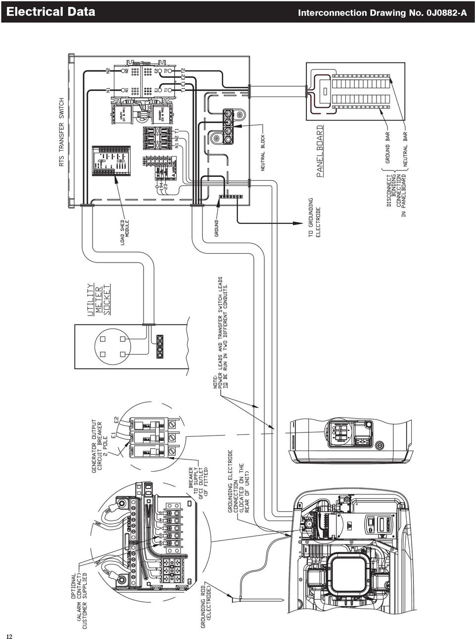
14 Electrical Data Interconnection Drawing No. 0J0882-A 12
15 Interconnection Drawing No. 0J0893-A Electrical Data 13

16 Electrical Data Schematic Drawing No. 0H7255-A 14

17 Schematic Drawing No. 0H7255-A Electrical Data 15

18 Exploded Views & Parts Lists 100A Assembly Drawing No. 0H7262$-A Parts List on page

19 100A Assembly Drawing No. 0H7262$-A Exploded Views & Parts Lists Parts List on page

20 Exploded Views & Parts Lists 100A Assembly Drawing No. 0H7262$-A ITEM PART NO. QTY. DESCRIPTION 1 0C TR SW-HSB 100A 2P 250V SCREW HHTT M5-0.8 X 10 BP LUG SLDLSS 1/0-#14X9/16 AL/CU 4 0G SCREW PPHM #10-32 X 5/ WASHER, LOCK # A SCREW HHTT M4-0.7 X 10 BP 7 0H WIRING HARNESS HSB (NOT SHOWN) (2) RELAY PNL 12VDC DPDT (2) 9 0D FUSEBLOCK 30A 600V 3 POLE A 3 FUSE 5A X BUSS HLDR73591 (2) 11 0H BLOCK, TERM 20A 5 X A RIVET, POP.156 X E ASS'Y NEUTRAL BLOCK 100A SCREW HHTT M6-1.0 X 12 MM 15 0G51590AL14 1 ENCLOSURE, 100/200A TRANSFER SWITCH 16 0G51740AL14 1 COVER, TRANSFER SWITCH 17 0G55920GS0R 1 SUBPLATE, 100/200A XFER SW 18 0D DECAL, FUSE REPLACEMENT 19 PER MODEL 1 DECAL, FRONT COVER ATS NEMA3R 20 0H DECAL, 2008 NEC COMPLIANCE 21 0G5968A REF DECAL, XFER SW NON 100A 120/240 0H8062A REF DECAL, XFER SW NON 100A 120/ A 1 DECAL, GROUNDING LUG 23 0A DECAL, NEUTRAL 24 0A DECAL, MANUAL 5A FUSE 25 0H DECAL, TERMINAL STRIP D 1 DECAL, TEST SEQUENCE DECAL, UL LIST HSB 28 0G DECAL, LIVE CIRCUIT ENG/FRN/SPN 29 0H DECAL, UTILITY LOAD SENSE 240V 30 0E GROUND BAR (5) 4-14 AWG CONN 31 0C NUT HEX LOCK M4-0.7 SS NYL INS WASHER SHAKEPROOF EXT #8 STEEL WASHER FLAT M SCREW HHC 1/4-20 X 1/2 SS 35 0F WASHER M6 NYLON INT HEX NUT HEX 1/4-20 SS WASHER FLAT 1/4-M6 ZINC WASHER LOCK M6-1/4 39 0E BRACKET, ARM EXTENDER (1) 40 0E ARM EXTENDER PIN 41 0D RIVET POP.156 X.362 AL 42 0E WIRE-A 43 0E6303C 1 WIRE-E LUG DIS QK NI-S 10X45 DEG BR/T 45 0H7376A 1 ASSY PCB AC LOAD CONTROLLER 46 0H CHANNEL SNAPTRACK 76.2 X E 1 NUT TRIC 1/4-20 X.525 (1) SUPPLIED WITH TRANSFER SWITCH ITEM #1 (2) SUPPLIED WITH HARNESS (P/N 0H7258) 18

21 200A Assembly Drawing No. 0H7263$-A Exploded Views & Parts Lists Parts List on page
22 Exploded Views & Parts Lists 200A Assembly Drawing No. 0H7263$-A Parts List on page
23 200A Assembly Drawing No. 0H7263$-A Exploded Views & Parts Lists ITEM PART NO. QTY. DESCRIPTION 1 0D XFRSW HSB 200A 2P 250V SCREW HHTT M5-0.8 X 10 BP 3 0E LUG SLDLSS 250-#6 AL/CU 4 0F SCREW BHSC 1/4-20 X 3/ WASHER LOCK M6-1/4 6 0A SCREW HHTT M4-0.7 X 10 BP 7 0H WIRING HARNESS HSB (NOT SHOWN) (2) RELAY PNL 12VDC DPDT (2) 9 0D FUSEBLOCK 30A 600V 3 POLE A 3 FUSE 5A X BUSS HLDR73591 (2) 11 0H BLOCK, TERM 20A 5 X A RIVET, POP.156 X E3717A 1 ASS'Y NEUTRAL BLOCK 200A SCREW HHTT M6-1.0 X 12 MM 15 0G51590AL14 1 ENCLOSURE, 100/200A TRANSFER SWITCH 16 0G51740AL14 1 COVER, TRANSFER SWITCH 17 0G55920GS0R 1 SUBPLATE, 100/200A XFER SW 18 0D DECAL, FUSE REPLACEMENT 19 PER MODEL 1 DECAL, FRONT COVER ATS NEMA3R 20 0H DECAL, 2008 NEC COMPLIANCE 21 0G5968B REF DECAL, XFER SW NON 200A 120/240 0H8062B REF DECAL, XFER SW NON 200A 120/ A 1 DECAL, GROUNDING LUG 23 0A DECAL, NEUTRAL 24 0A DECAL, MANUAL 5A FUSE 25 0H DECAL, TERMINAL STRIP 26 0E DECAL, TEST SEQUENCE DECAL, UL LIST HSB 28 0G DECAL, LIVE CIRCUIT ENG/FRN/SPN 29 0H DECAL, UTILITY LOAD SENSE 240V 30 0E GROUND BAR (5) 4-14 AWG CONN 31 0C NUT HEX LOCK M4-0.7 SS NYL INS WASHER SHAKEPROOF EXT #8 STEEL WASHER FLAT M SCREW HHC 1/4-20 X 1/2 SS 35 0F WASHER M6 NYLON INT HEX NUT HEX 1/4-20 SS WASHER FLAT 1/4-M6 ZINC 38 0E BRACKET, ARM EXTENDER (1) 39 0E ARM EXTENDER PIN 40 0D RIVET POP.156 X.362 AL 41 0E WIRE-A 42 0E6303B 1 WIRE-E1 43 0E STRAIGHT SPADE CONNECTOR 44 0H7376A 1 ASSY PCB AC LOAD CONTROLLER 45 0H CHANNEL SNAPTRACK 76.2 X E 1 NUT TRIC 1/4-20 X.525 (1) SUPPLIED WITH TRANSFER SWITCH ITEM #1 (2) SUPPLIED WITH HARNESS (P/N 0H7258) 21
24 Part No. 0H7440 Revision C (08/31/10) Printed in U.S.A.
25 Manual técnico Interruptor inteligente Nexus Este manual deberá permanecer con la unidad. 23
26 Reglas de seguridad GUARDE ESTAS INSTRUCCIONES! Lea la siguiente información cuidadosamente antes de intentar instalar, operar o dar servicio a este equipo. También lea las instrucciones e información en las etiquetas y cal- comanías que pudieran estar fijadas en el interruptor de transferencia. Reemplace cualquier calcomanía o etiqueta que no sea legible. PELIGRO! La conexión de un generador a un sistema eléctrico normalmente suministrada por un servicio eléctrico público se hará por medio de un equipo de transferencia adecuado de modo de aislar el sistema eléctrico del sistema de distribución del servicio público cuando el generador está operando (Artículo 701, Sistemas de respaldo requeridos legalmente o Artículo 702 Sistemas de respaldo opcionales, según se aplique). El no ailsar el sistema eléctrico por estos medios puede traer como resultado daños al generador daños o muerte de los trabajadores del servicio público debido a la realimentación de la energía eléctrica. El fabricante no puede anticipar todas las posibles circunstancias que puedan involucrar peligros. Las advertencias en este manual y en las etiquetas y calcomanías fijadas en la unidad son, por tanto, no completamente inclusivas. Si se usa un procedimiento, método de trabajo o técnica de operación que el fabricante no recomienda específicamente, asegúrese de que sea seguro para los demás. Asimismo asegúrese que el procedimiento, método de trabajo o técnica elegida utilizada no vuelva inseguro al interruptor de transferencia. A lo largo de esta publicación, y en lo que respecta a las etiquetas y calcomanías fijadas en el generador, los bloques de PELIGRO, ADVERTENCIA, CUIDADO Y NOTA se usan para alertar al personal sobre instrucciones especiales sobre una operación en particular que puede ser peligrosa si se ejecuta en forma incorrecta o sin cuidado. Obsérvelas con cuidado. Sus definiciones son como sigue: PELIGRO Luego de este encabezado, lea las instrucciones que, si no se siguen estrictamente, traerán como resultado daños personales serios, incluyendo la muerte. ADVERTENCIA Luego de este encabezado, lea las instrucciones que, si no se siguen estrictamente, podría traer como resultado daños personales serios, incluyendo la muerte. CUIDADO Luego de este encabezado, lea las instrucciones que, si no se siguen estrictamente, pueden traer como resultado daños menores o moderados. NOTA: Luego de este encabezado, lea las instrucciones que, si no se siguen estrictamente, podrían traer como resultado daños al equipo y/o a la propiedad. Estas advertencias de seguridad no pueden eliminar los peligros que indican. El sentido común y un estricto cumplimiento de las instrucciones especiales cuando se realiza un servicio son esenciales para evitar accidentes. Cuatro símbolos de seguridad usados comúnmente acompañan los bloques de PELIGRO, ADVERTENCIA y CUIDADO. El tipo de información que cada uno indica es como sigue: Este símbolo señala importante información de seguridad que, si no se sigue, puede poner en peligro la seguridad personal y/o a las propiedades. Este símbolo indica un peligro potencial de explosión. Este símbolo indica un peligro potencial de incendio. Este símbolo indica un peligro potencial de choque eléctrico. PELIGROS GENERALES Cualquier generador AC que se use para energía de respaldo cuando ocurra una falla de la fuente de energía NORMAL (SER- VICIO PÚBLICO), debe estar aislado de la fuente de energía NORMAL (DE SERVICIO PÚBLICO) por medio de un interruptor de transferencia aprobado. El no aislar apropiadamente las fuentes de energía NORMAL y de RESPALDO entre sí, puede traer como resultado daños o la muerte a los trabajadores del servicio público, debido a la retroalimentación de la energía aléctrica. Una instalación, operación, servicio o reparación del equipo no apropiada o no autorizada es extremadamente peligrosa y puede traer como resultado la muerte, daños personales serios o daños al equipo y/o a la propiedad personal. Voltajes de potencia extremadamente altos y peligrosos están presentes dentro de un interruptor de transferencia instalado. Cualquier contacto con los terminales de alto voltaje, los contactos o cables traerá como resultado un choque eléctrico extremadamente peligroso y posiblemente LETAL. NO TRABAJE EN EL INTERRUPTOR DE TRANSFERENCIA HASTA QUE TODAS LAS FUENTES DE VOLTAJE AL INTERRUPTOR HAYAN SIDO POSITIVAMENTE APAGADAS. 24
27 Tabla de contenidos Personal competente y calificado deberá instalar, operar y dar servicio a este equipo. Adhiérase esctríctamente a los códigos nacionales, estatales y locales de electricidad y construcción. Al usar este equipo, cumpla con las regulaciones establecidas por el Código Eléctrico Nacional (NEC), el estándar CSA, El código eléctrico canadiense C22.1 y la administración de salud y seguridad ocupacional (OSHA). Nunca manipule ningun tipo de dispositivo eléctrico mientras esté de pie sobre agua, con los pies descalzos o con las manos o pies húmedos. PUEDE HABER UNA DESCARGA ELÉCTRICA COMO RESULTADO. Sáquese toda la joyería (anillos, relojes, brazaletes, etc.) antes de trabajar en este equipo. Si se tiene que hacer algún trabajo en este equipo estando de pie sobre metal o concreto, coloque alfombrillas aislantes sobre una plataforma de madera seca. Trabaje en este equipo sólo si se encuentra de pie sobre tales alfombras aislantes. Nunca trabaje en el equipo cuando esté física o mentalmente fatigado. Mantenga la puerta de la caja del interruptor de transferencia cerrada y empernada en todo momento. Sólo personal calificado deberá tener acceso al interior del interruptor. En caso de un accidente causado por descarga eléctrica, apague inmediatamente la fuente de energía eléctrica. Si esto no es posible, intente liberar a la víctima del conductor vivo pero EVITE EL CONTACTO DIRECTO CON LA VÍCTIMA. Une un implemento no conductivo, como una soga seca o una tabla, para liberar a la víctima del conductor vivo. Si la víctima está inconsciente, aplique los primeros auxilios y consiga ayuda médica inmediatamente. Cuando se instala un interruptor de transferencia automática para un generador de respaldo, el motor del generador puede arrancar en cualquier momento sin aviso. Para evitar un posible daño causado por tales arranques súbitos, el circuito de arranque automático del sistema debe estar deshabilitado antes de trabajar sobre o alrededor del generador o el interruptor de transferencia. Luego coloque una etiqueta de NO OPERAR sobre el interruptor de transferencia y sobre el generador. Retire el cable de batería Negativo (Neg) o ( ). Reglas de seguridad Tabla de contenidos Información General Introducción Desempaque Descripción de Equipo Calcomanía de datos del interruptor de transferencia Caja del interruptor de transferencia Uso seguro del interruptor de transferencia Instalación Introducción a la instalación Montaje Conexión de la fuente de energía y líneas de carga Mecanismo de dos polos Conexión de cables de circuito estrella Conexión de módulo de corte de alimentación (LSM) Secuencia de operación Operación Prueba funcional y ajustes Operaciones manuales Lado de fuente cerrar para normal Lado de fuente cerrar para emergencia Lado de fuente regresar a normal Revisiones de voltaje Pruebas del generador bajo carga Probando el módulo de corte de alimentación (LSM) Notas Para un servicio autorizado, ubique el número del representante dentro del manual de propietario del generador. 25
28 Información general 1.1 INTRODUCCIÓN Este manual ha sido preparado especialmente con el propósito de familiarizar al personal con el diseño, aplicación, instalación, operación y servicio del equipo aplicable. Lea el manual cuidadosamente y cumpla todas las instrucciones. Esto ayudará a evitar accidentes o daños al equipo que de otro modo podrían ser causados por descuido, aplicación incorrecta o procedimientos inapropiados. Se ha hecho el mayor esfuerzo para asegurarse que el contenido de este manual sea exacto y actualizado. El fabricante, sin embargo, se reserva el derecho de cambiar, alterar o de otro modo mejorar el producto en cualquier momento sin previo aviso. 1.2 DESEMPAQUE Desempaque cuidadosamente el interruptor de transferencia. Inspecciónelo de cerca por si hay algún daño ocurrido durante el embarque. El comprador debe reclamar al transportista por cualquier pérdida o daño incurrido durante el tránsito. Revise que todo el material de empaque esté completamente retirado del interruptor antes de la instalación. 1.3 DESCRIPCIÓN DEL EQUIPO El interruptor de transferencia automática se usa para transferir cargas eléctricas críticas de una fuente de energía de SERVICIO PÚBLICO (NORMAL) a una fuente de energía de GENERADOR (DE RESERVA). Dicha transferencia de cargas eléctricas ocurre automáticamente cuando la fuente de energía del SERVICIO PÚBLICO ha fallado o está reducida sustancialmente y el voltaje de fuente del GENERADOR y su frecuencia han alcanzado un nivel aceptable. El interruptor de transferencia evita la realimentación eléctrica entre dos fuentes de energía diferentes (como la de SERVICIO PÚBLICO y GENERADOR) y por esa razón los códigos los requieren en todas las instalaciones de sistemas eléctricos de respaldo. El interruptor de transferencia consiste en un mecanismo de transferencia, un control de relé, un controlador de corte de alimentación, una tira de terminal y un porta fusibles para conexión de los cables de sensado. Este interruptor es adecuado para el control de motores, lámparas de descarga eléctrica, filamentos de tungsteno y los equipos de calefacción eléctrica y carga de tungsteno no exceda el 30% del nominal del interruptor. Este interruptor de transferencia listado en UL se usará solamnete en sistemas de respaldo opcionales (NEC artículo 702). Un interruptor de 100A nominales es adecuado para usarse en circuitos capaces de entregar no más de 10,000 amperios simétricos RMS, 250 VAC máximo, al estar protegido por un interruptor de circuito de 100A (tipos Siemens QP o BQ) o un interruptor de circuito de 150A máximo (Square D Q2, Westinghouse CA-CAH, General Electric TQ2 y Siemens QJ2). Un interruptor de 200A nominales es adecuado para usarse sobre un circuito con capacidad de 10,000 amperios simétricos rms, 240 VAC al estar protegido por un interruptor de circuito sin respuesta de tiempo corto ajustable o por fusibles. El módulo de corte de alimentación está diseñado para evitar una sobrecarga en el generador cuando está suministrando a las cargas del cliente. Vea la figura 1.1. Hasta seis cargas se pueden manejar con el LSM; 2 cargas de aire acondicionado y 4 otras cargas. El LSM maneja las cargas cortando las cargas conectadas en caso de una caída en la frecuencia del generador (sobrecarga). Las cargas a ser cortadas se agrupan en 4 niveles de prioridad en el LSM. La prioridad 1 y 2 tiene conexiones para un aire acondicionado y un contactor. Un aire acondicionado y un contactor se puede usar al mismo tiempo si se desea. Para controlar un aire acondicionado, no se requiere equipamiento adicional. Los relés internos interrumpen la señal de control de 24 VAC del termostato para deshabilitar la carga del aire acondicionado. La prioridad 3 y 4 tienen conexiones para un contactor solamente. Cuatro LEDs, ubicados en el módulo de corte de alimentación, indicarán cuando un nivel de prioridad de carga está habilitado. Cualquier carga, incluyendo los aires acondicionados centrales, se pueden controlar a través de un contactor que debe adquirirse por separado. Hasta cuatro contactores se pueden controlar con el módulo de corte de alimentación. El LSM cuministra los 120 VAC para energizar la bobina del contactor. La condición de sobrecarga del generador está determinada por la frecuencia del generador. Las cargas se cortan cuando la frecuencia es <58Hz por segundos o <50Hz por 1/2 segundo (para 60Hz). El LSM tiene un botón de prueba que fuerza la unidad a actuar si ha ocurrido una sobrecarga. Este botón opera aún cuando la señal de transferencia está inactiva. Figura 1.1 Módulo de corte de alimentación Conexiones de aire acondicionado Hasta dos A/A se pueden controlar con cables de de termostato de bajo voltaje. LEDs de estatus: Muestra qué cargas pueden actualmente funcionar. 0 Ground V 23 Transfer T1 NEUTRAL AIR 1 CONTACTOR 1 AIR 2 CONTACTOR 2 Priority 1 CONTACTOR Priority 2 3 Priority 3 CONTACTOR 4 Priority 4 Conexiones de carga: hasta cuatro cargas de cualquier tipo pueden controlarse a través de estas conexiones. (Se requiere un módulo contactor separado). 26
29 Instalación 1.4 CALCOMANÍA DE DATOS DEL INTERRUPTOR DE TRANSFERENCIA Una CALCOMANÍA DE DATOS está fijada permanentemente a la caja del interruptor de transferencia. Use este interruptor de transferencia sólo dentro de los límites específicos mostrados en la CALCOMANÍA DE DATOS y en las otras calcomanías y etiquetas que pueden estar fijadas al interruptor. Esto evitará daños al equipo y la propiedad. Al solicitar información u ordenar repuestos para este equipo, asegúrese de incluir toda la información de la CALCOMANÍA DE DATOS. Registre el modelo y número de serie en el espacio proporcionado debajo para futuras referencias. MODELO # SERIE # 1.5 CAJA DEL INTERRUPTOR DE TRANSFERENCIA La caja del interruptor de transferencia estándar es del tipo UL 3R y NEMA. Las cajas de tipo 3R UL y NEMA proporcionan primariamente un grado de protección contra lluvia y aguanieve; no se dañan con la formación de hielo sobre la caja. 1.6 USO SEGURO DEL INTERRUPTOR DE TRANSFERENCIA Antes de instalar, operar o dar servicio a este equipo, lea estas REGLAS DE SEGURIDAD (cubierta frontal interior) con cuidado. Cumpla estrictamente con todas las REGLAS DE SEGURIDAD para evitar accidentes y/o daños al equipo. El fabricante recomienda que una copia de las REGLAS DE SEGURIDAD se coloque cerca del interruptor de transferencia. Asimismo, asegúrese de leer todas las instrucciones e información encontrada en las etiquetas y calcomanías fijadas al equipo. Dos publicaciones que describen el uso seguro de los interruptores de transferencia son los siguientes: NFPA 70; National Electrical Code UL 1008, STANDARD FOR SAFETY-AUTOMATIC TRANSFER SWITCHES NOTA: Es escencial usar la última versión de cualquier estándar para asegurarse de tener una información actual y correcta. 2.1 INTRODUCCIÓN A LA INSTALACIÓN Este equipo ha sido cableado y probado en fábrica. La instalación del interruptor incluye los siguientes procedimientos: Montaje de la caja. Conexión de la fuente de energía y las puntas de carga. Conexión del arranque del generador y circuitos de sensado. Conexión de cualquier contacto auxiliar (si es necesario) Conecte las cargas del módulo de corte de alimentación (como se requiera) Probando las funciones. 2.2 MONTAJE Las dimensiones de montaje para la caja del interruptor de transferencia se encuentran en este manual. Las cajas típicamente son montadas en la pared. Ver la sección de diagrama de instalación. CUIDADO Manipule los interruptores de transferencia con cuidado al instalarlos. No deje caer el interruptor. Proteja el interruptor contra impactos en todo momento, y contra arenillas de contrucción y restos metálicos. Nunca instale un interruptor de transferencia que haya sido dañado. Instale el interruptor de transferencia lo más cerca posible de las cargas eléctricas que van a ser conectadas a él. Monte el interruptor en forma vertical en una estructura rígida de soporte. Para evitar la distorsión del interruptor, nivele todos los puntos de montaje. Si es necesario, use arandelas detrás de los agujeros de montaje para nivelar la unidad. 2.3 CONEXIÓN DE LA FUENTE DE ENERGÍA Y LÍNEAS DE CARGA PELIGRO Asegúrese de apagar las fuentes de energía pública (NORMAL) y de emergencia (DE RESPALDO) antes de intentar conectar la fuente de energía y líneas de carga al interruptor de transferencia. Los voltajes de suministro son extremadamente altos y peligrosos. El contacto con dichas líneas de suministro de energía de alto voltaje traerá como resultado un choque eléctrico extremadamente peligroso, posiblemente letal. Los diagramas de cableado eléctrico se encuentran en el manual. La fuente de energía y las conexiones de carga se hacen en el mecanismo de transferencia, dentro de la caja del interruptor MECANISMO DE DOS POLOS Estos interruptores (figura 2.1) se usan con un sistema monofásico, cuando la línea NEUTRAL monofásica sea conectada a una arandela neutral y no vaya a ser conmutada. 27
30 Instalación Figura 2.1 Mecanismo típico de transferencia de dos polos (de 200 Amp mostrado) 28 BOBINA DE CIERRE DE ENERGÍA PÚBLICA BOBINA DE CIERRE DEL GENERADOR LENGÜETAS DE ENERGÍA PÚBLICA LENGÜETAS DE CARGA (T1 Y T2) LENGÜETAS DEL GENERADOR (E1 Y E2 Las lengüetas terminales para atornillar, sin soldadura, son las estándar. Nominal de interruptor Rango de cable Torque de ajuste del conductor 100A #14-1/0 AWG 50 in-lbs. 200A #6-250 MCM cm-lbs. Los tamaños de conductores debe ser adecuados para manipular la corriente máxima a la que estarán sujetos, basado en la columna de 75ºC de las tablas, gráficos, etc. usados para dimensionar conductores. La instalación debe cumplir completamente todos los códigos, estándares y regulaciones aplicables. Antes de conectar los cables a los terminales, retire cualquier óxido superficial de los extremos de los cables con un cepillo de alambre. Todos los cables de energía deberán ingresar al interruptor próximo a los terminales del mecanismo de transferencia. Si se usa conductores de ALUMINIO, aplique inhibidores de corrosión a los conductores. Ajuste las lengüetas terminales a los valores de torque como se anota en la calcomanía ubicada dentro de la puerta. Luego de ajustar las lengüetas terminales, limpie cualquier exceso de inhibidor de corrosión. Todos los cables de energía deberán ingresar al interruptor próximo a los terminales del mecanismo de transferencia. CUIDADO Use una llave de torque para ajustar los conductores, asegurándose de no exagerar ni dañar la base del interruptor. Si no se ajusta lo suficiente, puede haber una conexión suelta, causando un exceso de calor que puede dañar la base del interruptor. Conecte los conductores de carga de la fuente de energía a las lengüetas terminales del mecanismo de transferencia claramente marcadas como sigue: 1. Conecte los cables de fuente de energía COMERCIAL (NORMAL) a los terminales N1 y N2 del interruptor. 2. Conecte los cables de energía de fuente de EMERGENCIA (DE RESPALDO) a los terminales E1 y E2 del interruptor de transferencia. 3. Conecte las puntas de CARGA del cliente a los terminales T1 y T2 del interruptor. Los conductores deben estar soportados en forma apropiada, de calidad aislante aprobada, protegidos por conductos aprobados, y del tamaño de calibre correcto de acuerdo a los códigos aplicables. Asegúrese de mantener la claridad eléctrica apropiada entre las partes de metal vivo y el metal conectado a tierra. Deje al menos 1/2 pulgada para circuitos de 100 a 400 amperios. 2.4 CONEXIÓN DE LOS CABLES DE CIRCUITO Las interconexiones del sistema de control (sección de datos eléctricos) consiste en UTILITY 1 (N1), UTILITY 2 (N2) y LOAD (T1), y las puntas 23 y 194. Los tamaños de calibre de cable para este cableado depende de la longitud del cable como se recomienda en la siguiente gráfica: LONGITUD MÁX/ CABLE TAMAÑO RECOM/ CABLE 14, cm (140m) No. 18 AWG. de 461 a 730 pies (223m) No. 16 AWG. de 731 a 1,160 pies (354m) No. 14 AWG. 1,161 a 1,850 pies (565m) No. 12 AWG. 2.5 CONEXIÓN - MÓDULO CORTE DE ALIMENTACIÓN (LSM) El LSM puede controlar un aire acondicionado (24 VAC) directamente o un contactor separado (120 VAC) que puede controlar cualquier carga conectada a él. Vea la figura SECUENCIA DE OPERACIÓN Los 4 LEDs verdes de estatus indicarán cuando un nivel de prioridad de carga esté habilitado. Todas las cargas están habilitadas cuando la señal de transferencia está apagada. (ATS en posición de servicio público). Si la señal de transferencia está abajo (activa) Todas las cargas están habilitadas hasta que se detecte una sobrecarga Cuando se detecta una sobrecarga todas las cargas se deshabilitan Luego de 5 minutos, las cargas de prioridad 1 se habilitan. Y luego de 30 segundos, las cargas de prioridad 2 se habilitan. 30 segundos después, las cargas de prioridad 3 se habilitan. 30 segundos después, las cargas de prioridad 4 se habilitan. Si se detecta una sobrecarga dentro de los 50 segundos de habilitar un nivel, todas las cargas se deshabilitan otra vez y la secuencia se repite. Sin embargo, el nivel que causó la sobrecarga y todos los niveles mayores no serán habilitados nuevamente por 30 minutos.
31 Instalación Figura 2.2 Conexiones del módulo de corte de alimentación Fuente Cable Y Cable Y 0 Ground V 23 Transfer T1 AIR 1 AIR 2 Priority 1 Priority 2 Priority 3 Priority 4 NEUTRAL CONTACTOR 1 CONTACTOR 2 CONTACTOR 3 CONTACTOR 4 Contactor #1 Carga #1 Fuente Contactor #2 Carga #2 Cables de bobina Fuente Contactor #3 Carga #3 Fuente Contactor #4 Carga #4 Control de carga de aire acondicionado 1. Enrute el cable del termostato (des de la chimenea/termostato a la unidad de aire acondicionado exterior) al interruptor de transferencia. 2. Conecte el cable a los terminales de la tira terminal (Air 1) en el LSM como se muestra en la Figura 2.2. Estos son contactos normalmente cerrados que se abren en condiciones de corte de alimentación. Enrute el cable del termostato lejos de los cables de alto voltaje. 3. Si se requiere, conecte el segundo aire acondicionado a los terminales de la tira terminal (Air 2). Nominales del contacto Air 1 y 2 24 VAC, 5.0 Amps Max NOTA: Estas instrucciones son para una instalación típica de aire acondicionado. El control de la bomba de calor y los aires acondicionados de 2 etapas requerirá conexiones especiales. Control de un conector separado Un módulo de relé contactor separado se puede adquirir del fabricante. Si se usa un relé diferente debe tener un voltaje de bobina de 120 VAC. El LSM suministra 120 VAC con fusibles de 5A para energizar las bobinas de los contactores del relé (contactor 1, 2, 3 o 4). 1. Monte el módulo contactor y conecte la carga a los contactos principales. 2. Conecte la bobina del contactor a los terminales dell LSM deseado (contactor 1, 2, 3 o 4) en la tira terminal. 3. Conecte los contactores de corte de alimentación adicionales en forma similar. NOTA: Será necesario determinar el orden del corte de las cargas conectadas y conectar las cargas al LSM en ese orden. Uno es la más alta prioridad y cuatro es la prioridad más baja. 29
32 Operación 3.1 PRUEBAS FUNCIONALES Y AJUSTES Luego de la instalación e interconexión del interruptor de transferencia, inspeccione la instalación completa con cuidado. Un electricista competente y calificado deberá hacer la inspección. La instalación debe cumplir estrictamente todos los códigos, estándares y regulaciones aplicables. Cuando esté completamente seguro de que la instalación es la apropiada y correcta complete una prueba funcional del sistema. CUIDADO Realice pruebas funcionales en el orden exacto presentado en este manual, o se hará daño al interruptor. IMPORTANTE: Antes de proceder con las pruebas funcionales, lea y asegúrese de que todas las instrucciones e información en esta sección hayan sido entendidas. Asimismo, lea la información e instrucciones de las etiquetas y calcomanías fijadas al interruptor. Notar cualquier opción o accesorios que puedan estar instalados y revise su operación. 3.2 OPERACIÓN MANUAL PELIGRO NO transfiera manualmente bajo carga. Desconecte el interruptor de transferencia de toda fuente de energía por medios aprobados, como un interruptor de circuito principal. Se incluye un MANUBRIO manual con el interruptor de transferencia. La operación manual debe revisarse ANTES de que el interruptor de transferencia sea operado eléctricamente. Para revisar la operación manual, proceda como sigue: 1. Ponga el interruptor de AUTO/OFF/MANUAL en la posición OFF. 2. Apague las fuentes de energía COMERCIAL y de EMERGENCIA al interruptor de transferencia, con cualquier medio provisto (como los interruptores de circuito de linea principales). 3. Note la posición de los contactos principales del mecanismo de transferencia observando el brazo portador de contacto movible. El manubrio de operación manual hacia la parte superior del mecanismo del interruptor - terminales de CARGA (T1,T2) están conectados a los terminales de electricidad COMER- CIAL (N1, N2). El manubrio de operación manual hacia la parte inferior del mecanismo del interruptor - terminales de CARGA (T1,T2) están conectados a los terminales de electricidad DE EMER- GENCIA (E1, E2). CUIDADO No use fuerza excesiva al operar el interruptor de transferencia manualmente o se puede hacer daño al manubrio manual LADO DE FUENTE CERRAR PARA NORMAL Antes de proceder, verifique la posición del interruptor observando la posición del manubrio de operación manual en la figura 3.1 Si el manubrio está ARRIBA, los contactos están cerrados en la posición NORMAL, no se requiere mayor acción. Si el manubrio está ABAJO, proceda con el paso 1. Paso 1: Con el manubrio insertado en el eje actuador, mueva el manubrio ARRIBA. Asegúrese de sostener el manubrio ya que se moverá rápidamente luegro del centro del recorrido LADO DE FUENTE CERRAR PARA EMERGENCIA Antes de proceder, verifique la posición del interruptor observando la posición del manubrio de operación manual en la figura 3.1 Si el manubrio está ABAJO, los contactos están cerrados en la posición de EMERGENCIA (RESPALDO). No se requiere otra acción. Si el manubrio está ARRIBA, proceda con el paso 1. Paso 1: Con el manubrio insertado en el eje actuador, mueva el manubrio ABAJO. Asegúrese de sostener el manubrio ya que se moverá rápidamente luegro del centro del recorrido LADO DE FUENTE REGRESAR A NORMAL Active manualmente el interruptor para regresar el manubrio de operación manual a la posición ARRIBA. 3.3 REVISIONES DE VOLTAJE 1. Encienda el suministro de energía pública al interruptor de transferencia con cualquier medio provisto (como un interrutpor de línea principal pública). PELIGRO PROCEDA CON PRECAUCIÓN. EL INTERRUPTOR DE TRANSFERENCIA ESTÁ AHORA ELÉCTRICAMENTE CALIENTE. EL CONTACTO CON LOS TERMINALES VIVOS TRAE COMO RESULTADO UN CHOQUE ELÉCTRICO EXTREMADAMENTE PELIGROSO Y POSIBLEMENTE FATAL. 2. Con un voltímetro AC adecuado, revise el voltaje correcto. Suministro de electricidad comercial monofásica: Medir a través de las lengüetas N1 y N2 del ATS. También revise N1 a NEUTRAL y N2 a NEUTRAL. 3. Cuando esté seguro de que el voltaje de la fuente de energía PÚBLICA sea correcto y compatible con los valores del interruptor de transferencia, apague la fuente de energía pública al interruptor de transferencia. 4. En el panel del generador, coloque el interruptor de AUTO/ OFF/MANUAL en MANUAL. El generador deberá arrancar. 5. Deje que el generador se estabilice y caliente sin carga por al menos cinco minutos. 6. Fije el interruptor principal del circuito (CB1) en su posición ON (o en CLOSED). 30
33 Operación Figura 3.1 Interruptor de transferencia activándose Una el manubrio al eje actuador NOTE: Regrese manubrio a posición de almacenaje en caja al terminar con la transferencia manual Mueva manubrio ARRIBA para posición NORMAL (PÚBLICO). Mueva manubrio ABAJO para posición de EMERGENCIA (RESPALDO). PELIGRO PROCEDA CON PRECAUCIÓN. EL VOLTAJE DE SALIDA DEL GENERADOR ESTÁ AHORA SIENDO ENTREGADO A LOS TERMINALES DEL INTERRUPTOR DE TRANSFERENCIA. EL CONTACTO CON LOS TERMINALES VIVOS TRAE COMO RESULTADO UN CHOQUE ELÉCTRICO EXTREMADAMENTE PELIGROSO Y POSIBLEMENTE FATAL. 7. Con un voltímetro AC adecuado y un medidor de frecuencia, revise el voltaje y la frecuencia sin carga. Suministro monofásico del generador: Medir a través de las lengüetas E1 y E2 del ATS. También revise E1 a neutro y E2 a neutro. a. Frecuencia Hertz b. Terminales E1 a E VAC c. Terminales E1 a NEUTRAL VAC d. Terminales E2 a NEUTRAL VAC 8. Fije el interruptor principal del circuito (CB1) en su posición OFF (o en OPEN). 9. Coloque el interruptor de AUTO/OFF/MANUAL en posición OFF para apagar el generador. NOTA: NO proceda hasta que el voltaje de salida AC del generador y la frecuencia sean las correctas y dentro de los límites establecidos. Si el voltaje sin carga es el correcto pero la frecuencia sin carga es incorrecta, la velocidad del motor puede requerir un ajuste. Si la frecuencia sin carga es la correcta pero no el voltaje, el regulador de voltaje puede requerir un ajuste. 31
34 Operación 3.4 PRUEBAS DEL GENERADOR BAJO CARGA 1. Fije el interruptor principal del circuito en su posición OFF o en OPEN. 2. Active manualmente los contactos principales del interruptor de transferencia a su posición de EMERGENCIA (RESPALDO). Consulte la sección Operación manual. 3. Para arrancar el generador, coloque el interruptor de AUTO/ OFF/MANUAL en MANUAL. Cuando el motor arranque, déjelo estabilizarse por unos pocos minutos. 4. Gire el interruptor principal del circuito en su posición ON o en CLOSED. El generador ahora energiza a todos los circuitos de CARGA. Revise la operación del generador bajo carga como sigue: Encienda las cargas eléctricas a la capacidad de corriente/potencia nominal completa del generador. NO SOBRECARGUE. Con la máxima carga nominal aplicada, revise el voltaje y la frecuencia a través de los terminales E1 y E2 del interruptor de transferencia. El voltaje deberá ser mayor a 230 voltios y la frecuencia deberá ser mayor que 59 Hz. Deje que el generador funcione bajo la carga nominal por al menos 30 minutos. Con la unidad en duncionamiento, escuche si hay ruidos inusuales, vibraciones, sobrecalentamiento, etc, que pueda indicar un problema. 5. Cuando el chequeo bajo carga se haya completado, coloque el interruptor principal de circuito del generador en su posición APAGADO o ABIERTO. 6. Deje que el generador funcione sin carga por varios minutos. Luego apague colocando el interruptor de AUTO/OFF/ MANUAL en su posición APAGADO. 7. Mueva los contactos principales del interruptor de regreso a su posición de suministro PÚBLICO. Por ejemplo, carga conectada a fuente de energía PÚBLICA. Consulte la sección Operación manual. La palanca de operación y el manubrio del interruptor de transferencia deberán estar en posición ARRIBA. 8. Encienda el suministro de energía PÚBLICA al interruptor de transferencia usando los medios provistos (como un interrutpor de línea principal PÚBLICA). La fuente de energía PÚBLICA ahora energiza las cargas. 9. Ponga el interruptor de AUTO/OFF/MANUAL en la posición AUTO. El sistema está ahora listo para operación automática. 3.5 PROBANDO EL MÓDULO DE CORTE DE ALIMENTACIÓN (LSM) Se proporciona un botón de pruebas en la parte inferior del LSN para probar la operación de las funciones. El botón de pruebas funcionará cuando el ATS esté en posición de generador o de energía pública. 1. Encienda el suministro eléctrico público al ATS. 2. Presione el botón de PRUEBA en el LSM. 3. Verifique que todas las cargas conectadas a ser cortadas estén deshabilitadas. El método de verificación dependerá del tipo de carga. 4. Luego de 5 minutos, verifique que las cargas de prioridad 1 se habiliten. El LED de estatus L1 y Air1 está encendido. 5. Luego de otros 30 segundos, verifique que las cargas de prioridad 2 se habiliten. El LED de estatus L2 y Air 2 está encendido. 6. Luego de otros 30 segundos, verifique que las cargas de prioridad 3 se habiliten. El LED de estatus L3 está encendido. 7. Luego de otros 30 segundos, verifique que las cargas de prioridad 4 se habiliten. El LED de estatus L4 está encendido. 32
35 Notas 33
36 Parte No. 0H7440 Revisión C (08/31/10) Impreso en los EE.UU.
37 Manuel technique Commutateur intelligent Nexus Ce manuel doit accompagner l'unité. 35
38 Règles de sécurité CONSERVER CES CONSIGNES! Lire attentivement les informations suivantes avant d'essayer d'installer, de faire fonctionner ou d'effectuer l'entretien de cet équipement. Lire également les consignes et informations figurant sur les étiquettes qui peuvent être apposées sur le commutateur de transfert. Remplacer toute étiquette qui n'est plus lisible. DANGER! Le branchement d'un générateur à un système électrique normalement alimenté par une source électrique publique doit être effectué à l'aide de l'équipement de transfert adapté afin d'isoler le système électrique du système de distribution publique lorsque le générateur fonctionne (Article 701 Legally Required Standby Systems (Systèmes de secours légalement exigés) ou Article 702 Optional Standby Systems (Systèmes de secours opérationnels), le cas échéant). Le fait de ne pas isoler un système électrique par ces moyens peut endommager le générateur et peut également causer des blessures ou la mort pour les électriciens en raison de la réalimentation de l'énergie électrique. Le fabricant ne peut pas anticiper toutes les situations possibles qui peuvent impliquer un danger. Les avertissements de ce manuel et figurant sur les étiquettes et les autocollants apposés sur l'unité ne sont, toutefois, pas exhaustifs. Si vous suivez une procédure, une méthode de travail ou une technique de fonctionnement que le fabricant ne recommande pas en particulier, assurez-vous qu'elle est sans danger pour les autres. S'assurer que la procédure, la méthode de travail ou la technique de fonctionnement choisie ne rende pas le commutateur de transfert dangereux. Dans tout ce manuel, et sur les étiquettes et sur les autocollants apposés sur le générateur, les blocs DANGER, AVERTISSEMENT, ATTENTION et REMARQUE servent à alerter le personnel d'instructions spéciales au sujet d'une opération spécifique qui peut s'avérer dangereuse si elle n'est pas effectuée correctement ou avec précaution. Les respecter attentivement. Leurs définitions sont les suivantes : Après ce titre, lire les instructions qui, si elles ne sont pas strictement respectées, entraîneront des blessures corporelles graves, y compris la mort. AVERTISSEMENT! Après ce titre, lire les instructions qui, si elles ne sont pas strictement respectées, entraîneront des blessures corporelles graves, y compris la mort. ATTENTION! Après ce titre, lire les instructions qui, si elles ne sont pas strictement respectées, peuvent entraîner des blessures légères ou modérées. REMARQUE : Après ce titre, lire les instructions qui, si elles ne sont pas strictement respectées, peuvent entraîner des dommages à l'équipement et/ou aux biens. Ces avertissements de sécurité ne peuvent pas éliminer les dangers qu'ils signalent. Le bon sens et le respect strict des instructions spéciales lors de l'entretien sont essentiels pour éviter les accidents. Quatre symboles de sécurité communément utilisés accompagnent les blocs DANGER, AVERTISSEMENT et ATTENTION. Chacun des blocs véhicule un type d'informations : Ce symbole indique des informations importantes relatives à la sécurité qui, si elles ne sont pas suivies, pourraient mettre en danger la sécurité personnelle et/ou les biens. Ce symbole indique un risque potentiel d'explosion. Ce symbole indique un risque potentiel d'incendie. Ce symbole indique un risque potentiel d'électrocution. DANGERS GÉNÉRAUX Tout générateur CA, qui est utilisé pour l'alimentation de secours en cas de coupure de la source d'alimentation NORMAL (Normale) (UTILITY (RÉSEAU PUBLIC)), doit être isolé de la source d'alimentation NORMAL (Normale) (UTILITY (RÉSEAU PUBLIC)) au moyen d'un commutateur de transfert approuvé. Le fait de ne pas isoler correctement les sources d'alimentation NORMAL (Normale) et STANDBY (Secours) l'une de l'autre peut entraîner des blessures ou la mort pour les électriciens, en raison de la réalimentation de l'énergie électrique. L'installation, le fonctionnement, l'entretien ou la réparation inapproprié(e) ou non autorisé(e) de l'équipement est extrêmement dangereux (dangereuse) et peut entraîner la mort, des blessures corporelles graves, des dommages à l'équipement et/ ou aux biens personnels. Des tensions d'alimentation extrêmement élevées et dangereuses sont présentes à l'intérieur d'un commutateur de transfert installé. Tout contact avec les bornes, contacts ou fils à haute tension entraînera une électrocution extrêmement dangereuse et potentiellement MORTELLE. NE PAS TRAVAILLER SUR LE COMMUTATEUR DE TRANSFERT MANUELLEMENT TANT QUE TOUTES LES TENSIONS D'ALIMENTATION FOURNIES AU COMMUTATEUR DE TRANSFERT N'ONT PAS ÉTÉ MISES HORS TENSION POSITIVEMENT. Seul le personnel compétent et qualifié doit installer, faire fonctionner et effectuer l'entretien de cet équipement. Strictement respecter les codes de construction et électriques locaux, d'état et nationaux. Lors de l'utilisation de cet équipement, se conformer aux réglementations établies par le National Electric Code (NEC) (Code électrique national), la Norme CSA ; le Canadian Electric Code (Code électrique canadien) ou C22.1 et l'occupational Safety and Health Administration (OSHA) (Gestion de la sécurité et la santé au travail). 36
39 Table des matières Ne jamais manipuler tout type de dispositif électrique qui est dans l'eau, alors que vous êtes pieds nus ou que vos mains ou vos pieds sont mouillés. CELA ENTRAÎNERA UN RISQUE D'ÉLECTROCUTION. Retirer tous les bijoux (tels que les bagues, les montres, les bracelets, etc.) avant de travailler sur cet équipement. S'il faut effectuer un travail sur cet équipement alors que l'on se trouve sur du métal ou du béton, placer des tapis isolants sur une plateforme en bois sèche. Travailler sur cet équipement uniquement en se tenant sur ces tapis isolants. Ne jamais travailler sur cet équipement en cas de fatigue physique ou mentale. Garder la porte de l'enveloppe du commutateur de transfert fermée et boulonnée à tout moment. Seul le personnel qualifié doit être autorisé à accéder à l'intérieur du commutateur. En cas d'accident causé par électrocution, couper immédiatement la source d'alimentation électrique. Si cela n'est pas possible, essayer de libérer la victime du conducteur sous tension mais ÉVITER D'ENTRER EN CONTACT DIRECTEMENT AVEC LA VICTIME. Utiliser un objet non conducteur, comme une corde ou une planche sèche, pour libérer la victime du conducteur sous tension. Si la victime est inconsciente, assurer les premiers secours et demander une aide médicale immédiate. Lorsqu'un commutateur de transfert automatique est installé pour un générateur de secours, le moteur du générateur peut démarrer à tout moment sans prévenir. Afin d'éviter des blessures potentielles qui pourraient être causées par ces démarrages soudains, il faut désactiver le circuit de démarrage automatique du système avant de travailler sur ou autour du générateur ou du commutateur de transfert. Puis, apposer une étiquette «NE PAS FAIRE FONCTIONNER» sur le commutateur de transfert et le générateur. Retirer le câble Negative (Négatif) (Neg) ou ( ) de la batterie. Règles de sécurité Table des matiéres Informations générales Introduction Déballage Description de l'équipement Étiquette du commutateur de transfert Boîtier du commutateur de transfert Utilisation sécuritaire du commutateur de transfert Installation Introduction à l'installation Montage Branchement des fils de source d'alimentation et des fils de charge Mécanisme bipolaire Connexion des câbles de circuit de démarrage Branchement des connexions du module de délestage (LSM) Séquence de fonctionnement Fonctionnement Tests fonctionnels et réglages Fonctionnement manuel Fermeture du côté de la source d'alimentation normale Fermeture du côté de la source d'alimentation d'urgence Retour au côté de la source d'alimentation normale Vérifications de tension Tests du générateur sous charge Test du module de délestage (LSM) Remarques Pour un entretien autorisé, indiquer le numéro du dépositaire inscrit dans le manuel d'entretien du générateur. 37
40 Informations générales 1.1 INTRODUCTION Ce manuel a été spécialement préparé dans le but de familiariser le personnel avec la conception, l'application, l'installation, le fonctionnement et l'entretien de l'équipement applicable. Lire attentivement le manuel et respecter les consignes. Cela permettra d'éviter les accidents ou les dommages à l'équipement qui pourraient cependant être causés par imprudence, une application incorrecte ou des procédures inappropriées. Chaque effort a été fait afin de s'assurer que le contenu de ce manuel est exact et actuel. Cependant, le fabricant se réserve le droit de modifier, altérer ou autrement améliorer le produit, à tout moment, sans préavis. 1.2 DÉBALLAGE Déballer avec précaution le commutateur de transfert. L'inspecter de près afin de détecter tout dommage qui pourrait s'être produit pendant le transport. L'acheteur doit déposer toute réclamation auprès du transporteur en cas de perte ou de dommage survenu pendant le transport. Vérifier si tous les éléments d'emballage sont complètement retirés du commutateur avant de l'installer. 1.3 DESCRIPTION DE L'ÉQUIPEMENT Le commutateur de transfert automatique est utilisé pour transférer la charge électrique d'une source d'alimentation UTILITY (réseau public) (NORMAL (Normale)) à une source d'alimentation GENERATOR (Générateur) (STANDBY (Secours)). Ce type de transfert de charges électriques se produit automatiquement en cas de coupure ou de réduction importante de la source d'alimentation UTILITY (Réseau public) et lorsque la tension et la fréquence de la source GENERATOR (Générateur) ont atteint un niveau acceptable. Le commutateur de transfert empêche la rétroaction divergente électrique entre deux sources différentes d'alimentation (telles que les sources UTILITY (Réseau public) et GENERATOR (Générateur)) et, pour cette raison, les codes l'exigent dans toutes les installations de système électrique standard. Le commutateur de transfert se compose d'un mécanisme de transfert, d'u contrôle de relais, d'une commande de délestage, d'une bande terminale et d'un porte-fusible pour le raccordement des fils de détection. Ce commutateur est adapté pour le contrôle des moteurs, des lampes à décharge électrique, des équipements de chauffage électrique et à filament de tungstène et la charge de tungstène ne dépasse pas 30 % de la puissance de commutation. Ce commutateur de transfert homologué UL est utilisé uniquement dans les systèmes de secours en option (NEC, art. 702). Un interrupteur d'intensité nominale de 100 A peut être utilisé sur des circuits capables de fournir pas plus de RMS d'ampères symétriques, maximum de 250 VCA, lorsqu'ils sont protégés par un disjoncteur de 100 A maximum (Siemens, types QP ou BQ) ou un disjoncteur de 150 A maximum (Square D Q2, Westinghouse CA-CAH, General Electric TQ2 et Siemens QJ2). Un interrupteur d'intensité nominale de 200 A est adapté pour une utilisation sur un circuit capable de fournir RMS d'ampères symétriques, 240 VCA, lorsqu'il est protégé par un disjoncteur sans temps de réponse court réglable ou par des fusibles. Le module de délestage est conçu pour éviter une surcharge sur le générateur lors de l'approvisionnement des charges des clients. Voir le Schéma 1.1. La LSM peut gérer jusqu'à six charges ; 2 charges de climatiseur et 4 autres charges. Le LSM gère les charges en «délestant» les charges connectées en cas de chute de la fréquence du générateur (surcharge). Les charges à «délester» sont regroupés en 4 niveaux de priorité sur le LSM. La priorité 1 et 2 est reliée à un climatiseur et à un contacteur. Le climatiseur et le contacteur peuvent être utilisés en même temps si vous le désirez. Pour contrôler un climatiseur, aucun équipement supplémentaire n'est requis. Les relais internes interrompent le signal de contrôle du thermostat 24 VCA pour désactiver la charge de climatisation. La priorité 3 et 4 est reliée uniquement au contacteur. Quatre voyants, situés sur le module de délestage, indique quand un niveau de priorité de charge est activé. Les charges, y compris les climatiseurs centraux, peuvent être contrôlées via un contacteur qui doit être acheté séparément. Le LSM peut contrôler jusqu'à quatre contacteurs. Le LSM fournit les 120 VCA nécessaire pour alimenter en énergie chaque bobine du contacteur. La surcharge du générateur est déterminée par la fréquence du générateur. Les charges sont délestées lorsque la fréquence est < 58 Hz pour 3 secondes ou < 50 Hz pour 0,5 seconde (Pour 60 Hz). Le LSM est un bouton de test qui force l'unité à agir comme si une surcharge s'est produite. Ce bouton fonctionne même lorsque le signal de transfert est inactif. Schéma 1.1 Module de délestage Branchements du climatiseur : Jusqu'à deux climatiseurs peuvent être contrôlés à travers les fils à basse tension du thermostat Voyants de statut : Indique les charges actuellement autorisées pour le fonctionnement. 0 Ground Terre V 23 Transfert T1 NEUTRAL NEUTRE AIR 1 CONTACTEUR CONTACTOR 1 AIR 2 CONTACTEUR CONTACTOR 2 Priority Priorité 1 CONTACTEUR CONTACTOR Priority Priorité 2 3 Priority Priorité 3 CONTACTEUR CONTACTOR 4 Priority Priorité 4 Connexions de charge : Jusqu'à quatre charges de toute nature peuvent être contrôlées via ces connexions. (Un module de contacteur distinct est requis.) 38
41 Installation 1.4 ÉTIQUETTE DU COMMUTATEUR DE TRANSFERT Une ÉTIQUETTE est apposée en permanence sur le boîtier du commutateur de transfert. Utiliser ce commutateur de transfert uniquement dans les limites spécifiques indiquées sur l'éti- QUETTE et sur les autres étiquettes qui peuvent être apposées sur le commutateur. Cela empêchera les dommages à l'équipement et aux biens. Lors d'une demande d'informations ou d'une commande de pièces pour cet équipement, s'assurer d'inclure toutes les informations figurant sur l'étiquette. Noter les numéros de modèle et de série dans l'espace prévu ci-dessous pour mémoire. N DE MODÈLE N DE SÉRIE 1.5 BOÎTIER DU COMMUTATEUR DE TRANSFERT Le boîtier du commutateur standard est un type 3R homologué par la National Electrical Manufacturer s Association (NEMA) et UL. Les enveloppes de type 3R homologuées par UL et NEMA assurent principalement un degré de protection contre la pluie et le grésil et restent intactes en cas de formation de glace sur l'enveloppe. 1.6 UTILISATION SÉCURITAIRE DU COMMUTATEUR DE TRANSFERT Avant d'installer, de faire fonctionner ou d'effectuer l'entretien de cet équipement, lire attentivement les RÈGLES DE SÉCURITÉ (couverture intérieure). Respecter strictement toutes les RÈGLES DE SÉCURITÉ afin d'empêcher les accidents et/ou les dommages à l'équipement. Le fabricant recommande qu'une copie des RÈGLES DE SÉCURITÉ soit affichée à proximité du commutateur de transfert. Aussi, s'assurer de lire toutes les consignes et informations figurant sur les étiquettes apposées sur l'équipement. Les deux publications suivantes présentent l'utilisation sûre des commutateurs de transfert : NFPA 70 ; National Electrical Code (Code électrique national) UL 1008, NORME DE SÉCURITÉ POUR LES COMMUTATEURS DE TRANSFERT AUTOMATIQUES REMARQUE : Il est essentiel d'utiliser la dernière version de toute norme afin de s'assurer que les informations sont correctes et actuelles. 2.1 INTRODUCTION À L'INSTALLATION Cet équipement a été câblé et testé en usine. L'installation du commutateur inclut les procédures suivantes : Montage de l'enveloppe. Branchement des fils de source d'alimentation et des fils de charge. Branchement du circuit de démarrage et de détection du générateur. Connexion d'un contact auxiliaire (au besoin) Connecter les charges du module de délestage (si nécessaire) Test de fonctionnalités. 2.2 MONTAGE Les dimensions de montage pour le boîtier du commutateur de transfert sont contenues dans ce manuel. Les enceintes sont généralement fixées au mur. Voir la section «Schéma d'installation». ATTENTION! Manipuler les commutateurs de transfert avec précaution lors de l'installation. Ne pas faire tomber le commutateur. Protéger le commutateur contre les impacts à tout moment et contre les grains de construction et les éclats de métal. Ne jamais installer un commutateur de transfert qui a été endommagé. Installer le commutateur de transfert aussi près que possible des charges électriques qui sont branchées dessus. Monter le commutateur verticalement sur une structure de support rigide. Afin d'empêcher la distorsion du commutateur, niveler tous les points de montage. Si nécessaire, utiliser les rondelles derrière les trous de montage pour niveler l'unité. 2.3 BRANCHEMENT DES FILS DE SOURCE D'ALIMENTATION ET DES FILS DE CHARGE S'assurer de mettre HORS TENSION les alimentations UTILITY (Réseau public) (NORMAL (Normale)) et GENERATOR (Générateur) (STANDBY (Secours)) avant d'essayer de brancher les fils de source d'alimentation et les fils de charge au commutateur de transfert. Les tensions d'alimentation sont extrêmement hautes et dangereuses. Le contact avec ces lignes de source d'alimentation à haute tension cause une électrocution extrêmement dangereuse, potentiellement mortelle. Les diagrammes de câblage et les schémas électriques sont indiqués dans ce manuel. La source d'alimentation et les connexions de charge sont effectuées dans un mécanisme de transfert, à l'intérieur du boîtier du commutateur. 39
42 Installation MÉCANISME BIPOLAIRE Ces commutateurs (Schéma 2.1) sont utilisés avec un système monophasé, lorsque la ligne NEUTRAL (Neutre) doit être monophasée à une cosse neutre et n'est pas commutée. Schéma 2.1 Mécanisme de transfert bipolaire typique (200 A présenté) BOBINE D'ENCLENCHEMENT DU RÉSEAU PUBLIC BOBINE D'ENCLENCHEMENT DU GÉNÉRATEUR COSSES DU RÉSEAU PUBLIC COSSES DE CHARGE (T1 ET T2) Les cosses des bornes à vis sans soudure sont standard. Puissance de commutation Gamme des fils COSSES DU GÉNÉRATEUR (E1 ET E2) Couple de serrage du conducteur 100 A N 14-1/0 AWG 50 pi-lbs. 200 A N MCM 275 pi-lbs. Les tailles des conducteurs doivent être suffisantes pour gérer le courant maximal auquel ils seront soumis, sur la base de la colonne 75 C sur les tableaux, les graphiques, etc. utilisé pour mesurer les conducteurs. L'installation doit se conformer pleinement à tous les codes, normes et règlements. Avant de raccorder les câbles aux bornes de câblage, enlever les oxydes de surface des extrémités du câble avec une brosse métallique. Tous les câbles d'alimentation doivent entrer dans le commutateur près des terminaux de mécanisme de transfert. Si des conducteurs en ALUMINIUM sont utilisés, appliquer un inhibiteur de corrosion sur les conducteurs. Serrer les cosses selon les valeurs de couple indiquées sur l'étiquette située à l'intérieur de la porte. Après le serrage des cosses, essuyer soigneusement tout excès d'inhibiteur de corrosion. Tous les câbles d'alimentation doivent entrer dans le commutateur près des terminaux de mécanisme de transfert. ATTENTION! Utiliser une clé dynamométrique pour serrer les conducteurs, en s'assurant ne pas trop serrer, sinon cela pourrait endommager la base du commutateur. S'ils ne sont pas assez serrés, cela entraînerait un branchement desserré, causant un excès de chaleur qui pourrait endommager la base du commutateur. Brancher les conducteurs de charge de la source d'alimentation aux cosses du mécanisme de transfert clairement indiquées comme suit : 1. Connecter les câbles d'alimentation PUBLIQUE (NORMAL) aux commutateurs de borne N1, N2. 2. Connecter les câbles d'alimentation D'URGENCE (STANDBY) aux commutateurs de transfert de borne E1, E2. 3. Connecter les fils de la CHARGE client conduit aux commutateurs de borne T1, T2. Les conducteurs doivent être correctement soutenus, disposer des qualités isolantes approuvées, être protégés par un conduit approuvé et disposer de la bonne taille de calibre de fils conformément aux codes applicables. S'assurer de conserver la bonne distance électrique entre les pièces métalliques sous tension et le métal mis à la terre. Laisser 0,5 pouce minimum pour les circuits de A. 2.4 CONNEXION DES CÂBLES DE CIRCUIT DE DÉMARRAGE Les interconnexions du système de contrôle (Section Données électriques) composé d'utility 1 (N1), UTILITY 2 (N2) et LOAD (T1), et les fils 23 et 194. Les dimensions recommandées pour ce type de câble électrique dépend de la longueur du fil, tel que recommandé dans le diagramme suivant : LONGUEUR DE FIL MAXIMALE DIMENSION DE FIL RECOMMANDÉE 460 pieds (140 m) N 18 AWG. Entre 461 et 730 pieds (223 m) N 16 AWG. Entre 731 et pieds (354 m) N 14 AWG. Entre et pieds (565 m) N 12 AWG. 2.5 BRANCHEMENT DES CONNEXIONS DU MODULE DE DÉLESTAGE (LSM) Le LSM peut contrôler un climatiseur (24 Vca) directement ou un contacteur séparé (120 Vca) qui permet de contrôler toutes les charges connectées. Voir Schéma SÉQUENCE DE FONCTIONNEMENT Les 4 voyants de statut verts indiquent que le niveau de priorité de charge est activé. Toutes les charges sont activées lorsque le signal de transfert est éteint. (ATS en position Utility). Si le signal de transfert est abaissé (Actif) Toutes les charges sont activées jusqu'à détection d'une surcharge Quand une surcharge est détectée, toutes les charges sont désactivées Après 5 minutes, les charges de priorité 1 sont activées Après 30 secondes de plus, les charges de priorité 2 sont activées Après 30 secondes de plus, les charges de priorité 3 sont activées Après 30 secondes de plus, les charges de priorité 4 sont activées 40
43 Installation Schéma 2.2 Connections du module de délestage Alimentation Fil jaune 0 Ground Terre V 23 Transfert T1 AIR 1 NEUTRAL NEUTRE CONTACTEUR CONTACTOR Contacteur n 1 Alimentation Charge n 1 AIR 2 Priority Priorité 1 1 CONTACTEUR CONTACTOR 2 CONTACTEUR CONTACTOR Fils de bobine Contacteur n 2 Charge n 2 Priority Priorité 2 3 Alimentation Fil jaune Priority Priorité 3 Priority Priorité 4 CONTACTEUR CONTACTOR 4 Contacteur n 3 Charge n 3 Alimentation Contactor #4 Charge n 4 Si une surcharge est détectée dans les 30 secondes d'un niveau activé, toutes les charges sont désactivées à nouveau et la séquence recommence. Toutefois, le niveau qui a causé la surcharge et tous les niveaux supérieurs ne seront pas activés à nouveau pendant 30 minutes.contrôle de la charge de climatisation 1. Faire passer le câble du thermostat (à partir du four /thermostat à l'unité de conditionnement de l'air extérieur) vers le commutateur de transfert. 2. Relier le fil aux bandes de borne du bornier (Air 1) sur le LSM comme le montre la Schéma 2.2. Ce sont des contacts normalement fermés qui s'ouvrent sur des conditions de délestage. Faire passer le fil du thermostat loin des câbles de haute tension. 3. Si nécessaire, brancher le deuxième climatiseur aux bandes de borne du bornier (Air 2). Valeurs nominales de contact Air 1 et 2 24 VCA, 5 Max REMARQUE : Ces instructions sont pour une installation de climatiseur classique. Le contrôle de la pompe à chaleur et des climatiseurs biphasés nécessitera des raccordements spéciaux. Contrôle d'un contacteur séparé Un module de relais de contacteur séparé est disponible chez le fabricant. Si un relais différent est utilisé, il doit avoir une bobine de tension de 120 Vca. Le LSM fournit une énergie avec fusible (5 A) de 120 Vca pour alimenter les bobines de contacteurs relais (contacteur 1, 2, 3 ou 4). 1. Monter le module de contact et brancher la charge aux contacts principaux. 2. Connecter la bobine du contacteur aux bornes LSM désirées (contacteur 1, 2, 3 ou 4) sur le bornier. 3. Connecter chaque contacteur de délestage supplémentaire de la même façon. REMARQUE : Il sera nécessaire de déterminer l'ordre de «délestage» des charges connectées et de connecter les équipements au LSM dans cet ordre. 1 est la plus haute priorité et quatre est la plus faible priorité. 41
44 Fonctionnement 3.1 TESTS FONCTIONNELS ET RÉGLAGES Après l'installation et l'interconnexion du commutateur de transfert, inspecter attentivement toute l'installation. Un électricien compétent et qualifié doit l'inspecter. L'installation doit être strictement conforme à tous les codes, normes et réglementations applicables. Lorsque l'on est absolument sûr que l'installation est appropriée et correcte, effectuer un test fonctionnel du système. ATTENTION! Effectuer les tests fonctionnels dans l'ordre exact présenté dans ce manuel, sinon des dommages pourraient survenir au commutateur. IMPORTANT : Avant d'effectuer les tests fonctionnels, lire et s'assurer que toutes les consignes et informations de cette section sont comprises. Lire également les informations et consignes figurant sur les étiquettes apposées sur le commutateur. Noter toutes les options ou accessoires qui pourraient être installés, et revoir leur fonctionnement. 3.2 FONCTIONNEMENT MANUEL Ne PAS transférer manuellement sous charge. Débrancher le commutateur de transfert de toutes les sources d'alimentation à l'aide des moyens approuvés, tel(s) que le(s) principal (principaux) disjoncteur(s). Une POIGNÉE manuelle est fournie avec le commutateur de transfert. Il faut vérifier le fonctionnement manuel AVANT de faire fonctionner le commutateur de transfert électriquement. Afin de vérifier le fonctionnement manuel, effectuer les étapes suivantes : 1. Régler l'interrupteur AUTO/OFF/MANUAL (Auto/ arrêt/ manuel) du générateur sur la position OFF (Arrêt). 2. Mettre sur OFF les sources d'alimentation PUBLIQUE et D'URGENCE menant au commutateur de transfert, avec les moyens prévus (tels que les disjoncteurs de ligne principale). 3. Noter la position des principaux contacts du mécanisme de transfert en observant le bras de contact mobile du dispositif de transport. Poignée de fonctionnement manuel vers le haut du mécanisme de commutation - les bornes LOAD (CHARGE) (T1, T2) sont branchées aux bornes UTILITY (réseau public) (N1, N2). Poignée de fonctionnement manuel vers le bas du mécanisme de commutation - les bornes LOAD (CHARGE) (T1, T2) sont branchées aux bornes D'URGENCE (réseau public) (E1, E2). ATTENTION! Ne pas exercer de force excessive lors du fonctionnement manuel du commutateur de transfert, sinon des dommages pourraient survenir au niveau de la poignée manuelle FERMETURE DU CÔTÉ DE LA SOURCE D'ALIMENTATION PUBLIQUE Avant de continuer, vérifier la position du commutateur en observant la position de la poignée à fonctionnement manuel dans le Schéma 3.1. Si la poignée est sur la position UP (haut), les contacts sont fermés en position NORMAL (normale), aucune autre action n'est nécessaire. Si la poignée est sur la position DOWN (bas), effectuer l'étape 1. Étape 1 : Avec la poignée insérée dans l'arbre d'entraînement, mettre la poignée sur la position UP (haut). S'assurer de garder la poignée comme elle est, elle se déplacera plus rapidement après le centre de course FERMETURE DU CÔTÉ DE LA SOURCE D'ALIMENTATION D'URGENCE Avant de continuer, vérifier la position du commutateur en observant la position de la poignée à fonctionnement manuel dans le Schéma 3.1. Si la poignée est sur la position DOWN (bas), les contacts sont position DE SECOURS (STANDBY (Secours)). Aucune autre action n'est nécessaire. Si la poignée est sur la position UP (haut), effectuer l'étape 1. Étape 1 : Avec la poignée insérée dans l'arbre d'entraînement, mettre la poignée sur la position DOWN (bas). S'assurer de garder la poignée comme elle est, elle se déplacera plus rapidement après le centre de course RETOUR AU CÔTÉ DE LA SOURCE D'ALIMENTATION NORMALE Actionner manuellement le commutateur pour remettre la poignée de fonctionnement manuel sur la position UP (Haut). 3.3 VÉRIFICATIONS DE TENSION 1. Mettre sous tension l'alimentation électrique PUBLIQUE vers le commutateur de transfert à l'aide des moyens fournis (tels que le disjoncteur principal du réseau PUBLIC). FAIRE ATTENTION. LE COMMUTATEUR DE TRANSFERT EST DÉSORMAIS ÉLECTRIQUEMENT CHAUD. LE CONTACT AVEC LES BORNES SOUS TENSION ENTRAÎNE UNE ÉLECTROCUTION EXTRÊMEMENT DANGEREUSE ET POTENTIELLEMENT MORTELLE. 2. À l'aide d'un voltmètre CA précis, vérifier si la tension est correcte. Alimentation publique monophasée : Mesurer à travers les cosses N1 et N2 du CTA. Vérifier également N1 à NEUTRAL (Neutre) et N2 à NEUTRAL (Neutre). 3. Lorsque l'on est sûr que la tension de la source d'alimentation électrique PUBLIQUE est correcte et compatible avec les valeurs nominales du commutateur de transfert, mettre HORS TENSION l'alimentation électrique PUBLIQUE vers le commutateur de transfert. 4. Sur le panneau du générateur, régler l'interrupteur AUTO/OFF/ MANUAL (Auto/ arrêt/ manuel) sur la position MANUAL (Manuel). Le générateur doit démarrer. 5. Laisser le générateur se stabiliser et chauffer à circuit ouvert pendant cinq minutes au minimum. 42
45 Fonctionnement Schéma 3.1 Actionnement du commutateur de transfert Fixer la poignée sur l'arbre d'entraînement REMARQUE : Remettre la poignée en position de stockage dans un boîtier lorsque vous avez terminé le transfert manuel. Déplacer la poignée vers le haut (UP) pour la mettre en position NORMALE (UTILITY) (Réseau public). Déplacer la poignée vers le bas (DOWN) pour la mettre en position DE SECOURS (STANDBY). 6. Régler le disjoncteur principal (CB1) du générateur sur sa position ON (Marche) (ou CLOSED (Fermée)). FAIRE ATTENTION. LA TENSION DE SORTIE DU GÉNÉRATEUR EST DÉSORMAIS DÉLIVRÉE AUX BORNES DU COMMUTATEUR DE TRANSFERT. LE CONTACT AVEC LES BORNES SOUS TENSION ENTRAÎNE UNE ÉLECTROCUTION EXTRÊMEMENT DANGEREUSE ET POTENTIELLEMENT MORTELLE. 7. À l'aide d'un voltmètre CA et d'un fréquencemètre précis, vérifier la tension et la fréquence à circuit ouvert. Alimentation de générateur monophasée : Mesurer à travers les cosses E1 à E2 du CTA. Vérifier également E1 à NEUTRAL (Neutre) et E2 à NEUTRAL (Neutre). a. Fréquence...Entre 60 et 62 Hertz b. Bornes E1 à E2...Entre 240 et 246 VCA c. Bornes E1 à NEUTRAL (Neutre)...Entre 120 et 123 VCA d. Bornes E2 à NEUTRAL (Neutre)...Entre 120 et 123 VCA 8. Régler le disjoncteur principal (CB1) du générateur sur sa position OFF (Arrêt) (ou OPEN (Ouverte)). 9. Régler l'interrupteur AUTO/OFF/MANUAL (Auto / arrêt / manuel) sur la position OFF (Arrêt) pour arrêter le générateur. REMARQUE : Ne PAS continuer tant que la tension de sortie CA et la fréquence du générateur ne sont pas correctes et ne se trouvent pas dans les limites indiquées. Si la tension à circuit ouvert est correcte mais que la fréquence à circuit ouvert est incorrecte, la vitesse du moteur peut nécessiter un réglage. Si la fréquence à circuit ouvert est correcte mais que la tension n'est pas correcte, le régulateur de tension peut nécessiter un réglage. 43
46 Fonctionnement 3.4 TESTS DU GÉNÉRATEUR SOUS CHARGE 1. Régler le disjoncteur principal du générateur sur sa position OFF (Arrêt) ou OPEN (Ouverte). 2. Actionner manuellement les contacts principaux du commutateur de transfert sur leur position DE SECOURS (STANDBY (Secours)). Se reporter à la section «Fonctionnement manuel». 3. Pour démarrer le générateur, régler l'interrupteur AUTO/OFF/ MANUAL (Auto/ arrêt/ manuel) sur la position MANUAL (Manuel). Lorsque le moteur démarre, le laisser se stabiliser pendant quelques minutes. 4. Régler le disjoncteur principal du générateur sur sa position ON (Marche) ou CLOSED (Fermée). Le générateur alimente désormais tous les circuits de CHARGE. Vérifier le fonctionnement du générateur sous charge de la manière suivante : Mettre SOUS TENSION les charges électriques à la capacité de wattage / ampérage pleine du générateur. NE PAS SURCHARGER. Avec une charge nominale maximale appliquée, vérifier la tension et la fréquence à travers les bornes E1 et E2 du commutateur. La tension doit être supérieure à 230 V et la fréquence doit être supérieure à 59 Hertz. Laisser le générateur fonctionner sous charge nominale pendant 30 minutes au minimum. Avec l'unité en marche, détecter tout bruit, vibration, surchauffe, etc. inhabituel qui pourrait indiquer un problème. 5. Lorsque la vérification sous charge est effectuée, mettre le disjoncteur principal du générateur sur sa position OFF (Arrêt) ou OPEN (Ouverte). 6. Laisser le moteur fonctionner à circuit ouvert plusieurs minutes. Puis, fermer en réglant l'interrupteur AUTO/OFF/MANUAL (Auto / arrêt / manuel) sur sa position OFF (Arrêt). 7. Remettre les contacts principaux du commutateur sur leur position UTILITY (réseau public). Par exemple, la charge branchée à l'alimentation électrique du RÉSEAU PUBLIC. Se reporter à la section «Fonctionnement manuel». La poignée et le levier de commande du commutateur de transfert doivent être dans la position UP (haut). 8. Mettre sous tension l'alimentation électrique PUBLIC vers le commutateur de transfert à l'aide des moyens fournis (tel que le disjoncteur de la ligne d'alimentation PUBLIQUE principale). La source d'alimentation du réseau PUBLIC alimente désormais les charges. 9. Régler l'interrupteur AUTO/OFF/MANUAL (auto/arrêt/manuel) du générateur sur sa position AUTO. Le système est désormais prêt pour un fonctionnement automatique. 3.5 TEST DU MODULE DE DÉLESTAGE (LSM) Un bouton de test est prévu sur le fond du LSM pour tester le fonctionnement des fonctions testées. Le bouton de test fonctionne lorsque l'ats est en position UTILITY (réseau public) ou GENERATOR (générateur). 1. Mettre l'alimentation du réseau public (Utility) sur l'ats. 2. Appuyer sur le bouton TEST sur le LSM. 3. Vérifier que toutes les charges connectées à délester sont désactivées. La méthode de vérification dépendra du type de charge. 4. Après 5 minutes, vérifier que les charges de priorité 1 sont activées. Le voyant de statut L1 et Air 1 sont sur ON. 5. Après 30 autres secondes, vérifier que les charges de priorité 2 sont activées. Le voyant de statut L2 et Air 2 sont sur ON. 6. Après 30 autres secondes, vérifier que les charges de priorité 3 sont activées. Le voyant de statut L3 est sur ON. 7. Après 30 autres secondes, vérifier que les charges de priorité 4 sont activées. Le voyant de statut L4 est sur ON. 44
47 Remarques 45
48 Référence 0H7440 Révision C (08/31/10) Imprimé aux États-Unis
Contrôle d'accès Access control. Notice technique / Technical Manual
 p.1/18 Contrôle d'accès Access control INFX V2-AI Notice technique / Technical Manual p.2/18 Sommaire / Contents Remerciements... 3 Informations et recommandations... 4 Caractéristiques techniques... 5
Notice Technique / Technical Manual
 Contrôle d accès Access control Encodeur USB Mifare ENCOD-USB-AI Notice Technique / Technical Manual SOMMAIRE p.2/10 Sommaire Remerciements... 3 Informations et recommandations... 4 Caractéristiques techniques...
Paxton. ins-20605. Net2 desktop reader USB
 Paxton ins-20605 Net2 desktop reader USB 1 3 2 4 1 2 Desktop Reader The desktop reader is designed to sit next to the PC. It is used for adding tokens to a Net2 system and also for identifying lost cards.
Trim Kit Installation Instruction
 Trim Kit Installation Instruction Instrucciones para la Instalación del Kit de Molduras Instructions pour l'installation du Kit d'encastrement m If any hardware or parts are damaged or missing, contact
APPENDIX 6 BONUS RING FORMAT
 #4 EN FRANÇAIS CI-DESSOUS Preamble and Justification This motion is being presented to the membership as an alternative format for clubs to use to encourage increased entries, both in areas where the exhibitor
Lavatory Faucet. Instruction Manual. Questions? 1-866-661-9606 [email protected]
 Lavatory Faucet Instruction Manual rev. 19-01-2015 Installation Manual You will need Adjustable Wrench Adjustable Pliers Plumber s Tape Hardware list (included) Allen Key Socket wrench tool Important Follow
33 inch open & closed storage Rangement à espace fermé et ouvert de 33po (83.7cm) 33 pulgadas almacenaje abierto y cerra
 33 pulgadas almacenaje abierto y cerra") 33 inch open & closed storage 33 pulgadas almacenaje abierto y cerra! o not throw away packaging materials until assembly is complete.! Assemble this item on a soft surface, such as cardboard or carpet,
33 inch open & closed storage 33 pulgadas almacenaje abierto y cerra! o not throw away packaging materials until assembly is complete.! Assemble this item on a soft surface, such as cardboard or carpet,
ASSEMBLY INSTRUCTIONS DIRECTIVES POUR L'ASSEMBLAGE ombre pendant lamp lampe suspendue à tons dégradés, chocolat
 ASSEMBLY INSTRUCTIONS DIRECTIVES POUR L'ASSEMBLAGE ombre pendant lamp lampe suspendue à tons dégradés, chocolat SKU 2728089 INSTRUCTIONAL MANUAL MANUEL D'INSTRUCTIONS 270/2707 COMPONENT LIST LISTE DES
ASSEMBLY INSTRUCTIONS DIRECTIVES POUR L'ASSEMBLAGE luster chandelier lamp chandelier à trois branches en verre lustré
 ASSEMBLY INSTRUCTIONS DIRECTIVES POUR L'ASSEMBLAGE luster chandelier lamp chandelier à trois branches en verre lustré SKU 2711592 INSTRUCTIONAL MANUAL MANUEL D'INSTRUCTIONS 270/2707 COMPONENT LIST LISTE
Garage Door Monitor Model 829LM
 Garage Door Monitor Model 829LM To prevent possible SERIOUS INJURY or DEATH from a closing garage door: NEVER permit children to operate or play with door control push buttons or remote control transmitters.
Fabricant. 2 terminals
 Specifications Fabricant Nominal torque (Nm) 65 Minimal torque (Nm) 0,63 Coil resistance - 20 C (ohms) 20 Rated current DC (A) 1 Rotor inertia (kg.m 2 ) 2.10-3 Weight (kg) 7,20 Heat dissipation continuous
Instructions Mozilla Thunderbird Page 1
 Instructions Mozilla Thunderbird Page 1 Instructions Mozilla Thunderbird Ce manuel est écrit pour les utilisateurs qui font déjà configurer un compte de courrier électronique dans Mozilla Thunderbird et
ENGLISH 4 FRANÇAIS 6 ESPAÑOL 8
 SY ENGLISH 4 FRANÇAIS 6 ESPAÑOL 8 ENGLISH How to lubricate the sewing machine Warning! Always switch off the machine and disconnect it from the power supply before lubricating the sewing machine. 1 Always
Quick start guide. www.philips.com/support HTL1170B
 For product support, visit Para obtener asistencia técnica, visite Pour en savoir plus sur l assistance sur les produits, visitez le site www.philips.com/support HTL1170B Quick start guide P&F USA, Inc.
03/2013. Mod: WOKI-60IP/TR. Production code: DTWIC 6000
 03/2013 Mod: WOKI-60IP/TR Production code: DTWIC 6000 ENCASTRABLE INDUCTION DROP IN INDUCTION 11/2011 TECHNICAL FEATURES DOCUMENTATION S.A.V. Notice d utilisation : FX00326-A Guide d intervention : ---
Quick Installation Guide TEW-AO12O
 Quick Installation Guide TEW-AO12O Table of of Contents Contents Français... 1 1. Avant de commencer... 1 2. Installation du matériel... 2 3. Montage... 4 Troubleshooting... 6 Version 10.04.2007 1. Avant
Warning: Failure to follow these warnings could result in property damage, or personal injury.
 Western Steel & Tube 1 Storage Locker Extended Storage Locker Storage Cabinet Assembly And Use Instructions Warning: Failure to follow these warnings could result in property damage, or personal injury.
Installation Guide. Ceramic Oval Handle Trim Kit
 Installation Guide Ceramic Oval Handle Trim Kit K-251, K-253, K-258, K-260, K-262, K-264, K-273, K-274 M product numbers are for Mexico (i.e. K-12345M) Los números de productos seguidos de M corresponden
Package Contents. System Requirements. Before You Begin
 Package Contents DWA-125 Wireless 150 USB Adapter CD-ROM (contains software, drivers, and manual) Cradle If any of the above items are missing, please contact your reseller. System Requirements A computer
Comfort Duett. TV-kit. www.comfortaudio.com. USA: English/Français/Español. Comfort Duett
 Comfort Duett TV-kit USA: English/Français/Español www.comfortaudio.com Comfort Duett 1 English The television kit makes it possible to amplify the sound from the TV via the charger unit. As soon as Comfort
GIGABIT PCI DESKTOP ADAPTER DGE-530T. Quick Installation Guide+ Guide d installation+
 GIGABIT PCI DESKTOP ADAPTER Quick Installation Guide+ Guide d installation+ Check Your Package Contents Quick Installation Guide Gigabit Ethernet PCI Adapter CD with Manual and Drivers DO NOT insert the
Z-Axis Compliance Device Compliance en z
 Compensation for different vertical positions Collision recognition in Z-direction Protection of parts and work pieces Monitoring of the insertion forces during assembly operations Monitoring of the picking
Thank you for choosing the Mobile Broadband USB Stick. With your USB Stick, you can access a wireless network at high speed.
 Thank you for choosing the Mobile Broadband USB Stick. With your USB Stick, you can access a wireless network at high speed. Note: This manual describes the appearance of the USB Stick, as well as the
SA-32 / SA-62 INSTRUCTION MANUAL - MANUEL D INSTRUCTIONS
 SA-32 / SA-62 INSTRUCTION MANUAL - MANUEL D INSTRUCTIONS 4 5 6 7 4 5 6 7 1. Telephone Paging Volume Control 1. Contrôle de volume Paging Téléphone 2. Microphone Volume Control 2. Contrôle volume du microphone
Folio Case User s Guide
 Fujitsu America, Inc. Folio Case User s Guide I N S T R U C T I O N S This Folio Case is a stylish, lightweight case for protecting your Tablet PC. Elastic Strap Pen Holder Card Holders/ Easel Stops Figure
First Nations Assessment Inspection Regulations. Règlement sur l inspection aux fins d évaluation foncière des premières nations CONSOLIDATION
 CANADA CONSOLIDATION CODIFICATION First Nations Assessment Inspection Regulations Règlement sur l inspection aux fins d évaluation foncière des premières nations SOR/2007-242 DORS/2007-242 Current to September
CAR STEREO SPEAKER CS-AR500 CS-AR680 CS-AR650 CS-AR690 INSTRUCTION MANUAL MODE D EMPLOI MANUAL DE INSTRUCCIONES
 CAR STEREO SPEAKER HAUT-PARLEURS AUTO STEREO ALTAVOCES ESTEREOFONICOS PARA AUTOMOVIL CS-AR500 CS-AR680 CS-AR650 CS-AR690 INSTRUCTION MANUAL MODE D EMPLOI MANUAL DE INSTRUCCIONES LVT1744-001A Thank you
Quick Installation Guide TV-IP400 TV-IP400W
 Quick Installation Guide TV-IP400 TV-IP400W Table of of Contents Contents Français... 1. Avant de commencer... 2. Installation du matériel... 3. Configuration de la Webcam... Troubleshooting... 1 1 2 3
Thank you for choosing the Mobile Broadband USB Stick. With your USB Stick, you can access a wireless network at high speed.
 Thank you for choosing the Mobile Broadband USB Stick. With your USB Stick, you can access a wireless network at high speed. Note: This manual describes the appearance of the USB Stick, as well as the
Quick Installation Guide TBW-106UB H/W: V1
 Quick Installation Guide TBW-106UB H/W: V1 Table of Contents... 1. Avant de commencer... 2. Procéder à l'installation... 3. Configuration de l'adaptateur Bluetooth... Troubleshooting... 1 1 2 5 7 Version
Quick Installation Guide TW100-BRV304
 Quick Installation Guide TW100-BRV304 Table of of Contents Contents Français... 1. Avant de commencer... 2. Installation du matériel... 3. Configuration du routeur... 1 1 2 3 Troubleshooting... 5 Version
Guide d'installation rapide TFM-560X YO.13
 Guide d'installation rapide TFM-560X YO.13 Table of Contents Français 1 1. Avant de commencer 1 2. Procéder à l'installation 2 Troubleshooting 6 Version 06.08.2011 16. Select Install the software automatically
Instructions pour mettre à jour un HFFv2 v1.x.yy v2.0.00
 Instructions pour mettre à jour un HFFv2 v1.x.yy v2.0.00 HFFv2 1. OBJET L accroissement de la taille de code sur la version 2.0.00 a nécessité une évolution du mapping de la flash. La conséquence de ce
WINTER BOAT STORAGE SYSTEM SYSTÈME DE REMISAGE HIVERNAL POUR BATEAU
 MANUAL / MANUEL VIDEO WINTER BOAT STORAGE SYSTEM SYSTÈME DE REMISAGE HIVERNAL POUR BATEAU ASSEMBLY INSTRUCTIONS GUIDE D ASSEMBLAGE NAVIGLOO 14-18½ ft/pi FISHING BOAT! RUNABOUT! PONTOON BOAT! SAILBOAT (SAILBOAT
APPENDIX 2. Provisions to be included in the contract between the Provider and the. Holder
 Page 1 APPENDIX 2 Provisions to be included in the contract between the Provider and the Obligations and rights of the Applicant / Holder Holder 1. The Applicant or Licensee acknowledges that it has read
Cheque Holding Policy Disclosure (Banks) Regulations. Règlement sur la communication de la politique de retenue de chèques (banques) CONSOLIDATION
 Regulations. Règlement sur la communication de la politique de retenue de chèques (banques) CONSOLIDATION") CANADA CONSOLIDATION CODIFICATION Cheque Holding Policy Disclosure (Banks) Regulations Règlement sur la communication de la politique de retenue de chèques (banques) SOR/2002-39 DORS/2002-39 Current to
CANADA CONSOLIDATION CODIFICATION Cheque Holding Policy Disclosure (Banks) Regulations Règlement sur la communication de la politique de retenue de chèques (banques) SOR/2002-39 DORS/2002-39 Current to
WEB page builder and server for SCADA applications usable from a WEB navigator
 Générateur de pages WEB et serveur pour supervision accessible à partir d un navigateur WEB WEB page builder and server for SCADA applications usable from a WEB navigator opyright 2007 IRAI Manual Manuel
MAGNESIUM ENGLISH FRANÇAIS ESPAÑOL
 MAGNESIUM ENGLISH ESPAÑOL ENGLISH INSTALLATION INSTRUCTIONS CAUTION: Before starting, turn off power at main circuit panel. IMPORTANT SAFETY INSTRUCTIONS When installing or using the lighting system, basic
Le No.1 de l économie d énergie pour patinoires.
 Le No.1 de l économie d énergie pour patinoires. Partner of REALice system Economie d énergie et une meilleure qualité de glace La 2ème génération améliorée du système REALice bien connu, est livré en
R.V. Table Mounting Instructions
 PTSS165 ACCESSORY MOUNTING INSTRUCTIONS Use these instructions in conjunction with your main manual to properly assemble your gas grill. Refer to the main manual for safety, operating, cleaning and maintenance
TABLE DES MATIERES A OBJET PROCEDURE DE CONNEXION
 1 12 rue Denis Papin 37300 JOUE LES TOURS Tel: 02.47.68.34.00 Fax: 02.47.68.35.48 www.herve consultants.net contacts@herve consultants.net TABLE DES MATIERES A Objet...1 B Les équipements et pré-requis...2
SYSTÈME JETS D AIR WISH WISH AIR JETS SYSTEM Système de massage à jets d air pour bains en polymère - Air jet massage system for polymer bathtubs
 SYSTME JETS D AIR WISH WISH AIR JETS SYSTEM Système de massage à jets d air pour bains en polymère - Air jet massage system for polymer bathtubs Manuel d installation - Installation manual 6835, RUE PICARD
Support Orders and Support Provisions (Banks and Authorized Foreign Banks) Regulations
 Regulations") CANADA CONSOLIDATION CODIFICATION Support Orders and Support Provisions (Banks and Authorized Foreign Banks) Regulations Règlement sur les ordonnances alimentaires et les dispositions alimentaires (banques
CANADA CONSOLIDATION CODIFICATION Support Orders and Support Provisions (Banks and Authorized Foreign Banks) Regulations Règlement sur les ordonnances alimentaires et les dispositions alimentaires (banques
Credit Note and Debit Note Information (GST/ HST) Regulations
 Regulations") CANADA CONSOLIDATION CODIFICATION Credit Note and Debit Note Information (GST/ HST) Regulations Règlement sur les renseignements à inclure dans les notes de crédit et les notes de débit (TPS/ TVH) SOR/91-44
CANADA CONSOLIDATION CODIFICATION Credit Note and Debit Note Information (GST/ HST) Regulations Règlement sur les renseignements à inclure dans les notes de crédit et les notes de débit (TPS/ TVH) SOR/91-44
Stainless Steel Solar Wall Light
 V 2.9 Stainless Steel Solar Wall Light User Manual Please read and understand all instructions before use.retain this manual for future reference. V 2.9 Stainless Steel Solar Wall Light SPECIFICATIONS
This is a preview - click here to buy the full publication NORME INTERNATIONALE INTERNATIONAL STAN DARD. Telecontrol equipment and systems
 NORME INTERNATIONALE INTERNATIONAL STAN DARD CEI IEC 870-3 Première édition First edition 1989-03 Matériels et systèmes de téléconduite Troisième partie: Interfaces (caractéristiques électriques) Telecontrol
Export Permit (Steel Monitoring) Regulations. Règlement sur les licences d exportation (surveillance de l acier) CONSOLIDATION CODIFICATION
 Regulations. Règlement sur les licences d exportation (surveillance de l acier) CONSOLIDATION CODIFICATION") CANADA CONSOLIDATION CODIFICATION Export Permit (Steel Monitoring) Regulations Règlement sur les licences d exportation (surveillance de l acier) SOR/87-321 DORS/87-321 Current to August 4, 2015 À jour
CANADA CONSOLIDATION CODIFICATION Export Permit (Steel Monitoring) Regulations Règlement sur les licences d exportation (surveillance de l acier) SOR/87-321 DORS/87-321 Current to August 4, 2015 À jour
NORME INTERNATIONALE INTERNATIONAL STANDARD. Dispositifs à semiconducteurs Dispositifs discrets. Semiconductor devices Discrete devices
 NORME INTERNATIONALE INTERNATIONAL STANDARD CEI IEC 747-6-3 QC 750113 Première édition First edition 1993-11 Dispositifs à semiconducteurs Dispositifs discrets Partie 6: Thyristors Section trois Spécification
Règlement sur le télémarketing et les centres d'appel. Call Centres Telemarketing Sales Regulation
 THE CONSUMER PROTECTION ACT (C.C.S.M. c. C200) Call Centres Telemarketing Sales Regulation LOI SUR LA PROTECTION DU CONSOMMATEUR (c. C200 de la C.P.L.M.) Règlement sur le télémarketing et les centres d'appel
Railway Operating Certificate Regulations. Règlement sur les certificats d exploitation de chemin de fer CODIFICATION CONSOLIDATION
 CANADA CONSOLIDATION CODIFICATION Railway Operating Certificate Regulations Règlement sur les certificats d exploitation de chemin de fer SOR/2014-258 DORS/2014-258 Current to September 10, 2015 À jour
Contrôle d accès Access control MOD-TCPIP-AI. Notice technique / Technical Manual
 Contrôle d accès Access control MOD-TCPIP-AI Notice technique / Technical Manual Notice technique Mod-TCPIP-AI 9 septembre 2008 v.1.0 p.2/16 Sommaire / Contents Sommaire / Contents...2 Remerciements...3
Critères à l attention des fabricants et des fournisseurs de biens ou de services : dispositifs mécaniques pour bingo
 Alcohol and Gaming Commission des alcools Commission of Ontario et des jeux de l'ontario Gaming Registration & Lotteries Inscription pour les jeux et loteries 90 Sheppard Avenue East 90, avenue Sheppard
How to Login to Career Page
 How to Login to Career Page BASF Canada July 2013 To view this instruction manual in French, please scroll down to page 16 1 Job Postings How to Login/Create your Profile/Sign Up for Job Posting Notifications
Règlement sur l usage en commun de poteaux. Joint Use of Poles Regulations CODIFICATION CONSOLIDATION. C.R.C., c. 1185 C.R.C., ch.
 CANADA CONSOLIDATION CODIFICATION Joint Use of Poles Regulations Règlement sur l usage en commun de poteaux C.R.C., c. 1185 C.R.C., ch. 1185 Current to June 9, 2015 À jour au 9 juin 2015 Published by the
Ignition Module Instruction Manual Part#: 605, 609
 Ignition Module Instruction Manual Part#: 605, 609 IGNITION MODULE PN 605 and PN 609 INSTALLATION AND ELECTRICAL WIRING PROCEDURE A.0075" polyester gauge is provided to assist in setting the pickup gap.
Règlement relatif à l examen fait conformément à la Déclaration canadienne des droits. Canadian Bill of Rights Examination Regulations CODIFICATION
 CANADA CONSOLIDATION CODIFICATION Canadian Bill of Rights Examination Regulations Règlement relatif à l examen fait conformément à la Déclaration canadienne des droits C.R.C., c. 394 C.R.C., ch. 394 Current
DOCUMENTATION - FRANCAIS... 2
 DOCUMENTATION MODULE SHOPDECORATION MODULE PRESTASHOP CREE PAR PRESTACREA INDEX : DOCUMENTATION - FRANCAIS... 2 INSTALLATION... 2 Installation automatique... 2 Installation manuelle... 2 Résolution des
ETABLISSEMENT D ENSEIGNEMENT OU ORGANISME DE FORMATION / UNIVERSITY OR COLLEGE:
 8. Tripartite internship agreement La présente convention a pour objet de définir les conditions dans lesquelles le stagiaire ci-après nommé sera accueilli dans l entreprise. This contract defines the
AMENDMENT TO BILL 32 AMENDEMENT AU PROJET DE LOI 32
 THAT the proposed clause 6(1), as set out in Clause 6(1) of the Bill, be replaced with the following: Trustee to respond promptly 6(1) A trustee shall respond to a request as promptly as required in the
Ships Elevator Regulations. Règlement sur les ascenseurs de navires CODIFICATION CONSOLIDATION. C.R.C., c. 1482 C.R.C., ch. 1482
 CANADA CONSOLIDATION CODIFICATION Ships Elevator Regulations Règlement sur les ascenseurs de navires C.R.C., c. 1482 C.R.C., ch. 1482 Current to September 10, 2015 À jour au 10 septembre 2015 Last amended
INVESTMENT REGULATIONS R-090-2001 In force October 1, 2001. RÈGLEMENT SUR LES INVESTISSEMENTS R-090-2001 En vigueur le 1 er octobre 2001
 FINANCIAL ADMINISTRATION ACT INVESTMENT REGULATIONS R-090-2001 In force October 1, 2001 LOI SUR LA GESTION DES FINANCES PUBLIQUES RÈGLEMENT SUR LES INVESTISSEMENTS R-090-2001 En vigueur le 1 er octobre
BILL 203 PROJET DE LOI 203
 Bill 203 Private Member's Bill Projet de loi 203 Projet de loi d'un député 4 th Session, 40 th Legislature, Manitoba, 63 Elizabeth II, 2014 4 e session, 40 e législature, Manitoba, 63 Elizabeth II, 2014
Principe de TrueCrypt. Créer un volume pour TrueCrypt
 Sommaire : Principe de TrueCrypt...1 Créer un volume pour TrueCrypt...1 Premier montage...6 Réglages...8 Save Currently Mounted Volumes as Favorite...8 Settings > Preferences...9 TrueCrypt Traveller pour
Manuel d'utilisation
 HUNTER-PRO 32 vers. 3 RXN-416 Manuel d'utilisation PIMA Electronic Systems Ltd. 5 Hatzoref Street, Holon 58856, Israël +972-3-5587722 +972-3-5500442 [email protected] http://www.pima-alarms.com 2
that the child(ren) was/were in need of protection under Part III of the Child and Family Services Act, and the court made an order on
 was/were in need of protection under Part III of the Child and Family Services Act, and the court made an order on") ONTARIO Court File Number at (Name of court) Court office address Applicant(s) (In most cases, the applicant will be a children s aid society.) Full legal name & address for service street & number, municipality,
ONTARIO Court File Number at (Name of court) Court office address Applicant(s) (In most cases, the applicant will be a children s aid society.) Full legal name & address for service street & number, municipality,
Contents Windows 8.1... 2
 Workaround: Installation of IRIS Devices on Windows 8 Contents Windows 8.1... 2 English Français Windows 8... 13 English Français Windows 8.1 1. English Before installing an I.R.I.S. Device, we need to
de stabilisation financière
 CHAPTER 108 CHAPITRE 108 Fiscal Stabilization Fund Act Loi sur le Fonds de stabilisation financière Table of Contents 1 Definitions eligible securities valeurs admissibles Fund Fonds Minister ministre
Home Generator Systems. Installation & Operator s Manual. 100/200 Amp Automatic Transfer Switch with AC Power Control Module
 Home Generator Systems Installation & Operator s Manual 100/200 Amp Automatic Transfer Switch with AC Power Control Module Thank you for your purchase of this Briggs & Stratton Power Products automatic
FRENCH INSTALLATION DES BATTERIES FIXATION DU CHARGEUR CHARGER LE CHARGEUR ACTIVER LE CHARGEUR
 FRENCH INSTALLATION DES BATTERIES 1. Retirez le boulon qui maintient la porte de la batterie. 2. Retirez le support de la batterie. 3. Installez les batteries en accord avec la signalisation de polarité
Sécurité relative aux sièges auto et aux rehausseurs
 Sécurité relative aux sièges auto et aux rehausseurs Safety with Car Seats and Booster Seats Car crashes are the main cause of accidental death and serious injury of children. Correctly using a car or
Guide d installation Deco Drain inc. DD200
 Guide d installation Deco Drain inc. DD200 Pour plus informations et pour télécharger les guides d installation en couleur, visitez notre site web. www.decodrain.com Soutien technique : Composez le : 514-946-8901
Quick Installation Guide TV-IP212/TV-IP212W TV-IP312/TV-IP312W H/W: A1.0R
 Quick Installation Guide TV-IP212/TV-IP212W TV-IP312/TV-IP312W H/W: A1.0R Table Table of Contents of Contents... 1. Avant de commencer... 2. Installation du matériel... 3. Installation du serveur de caméra
DOCUMENTATION - FRANCAIS... 2
 DOCUMENTATION MODULE CATEGORIESTOPMENU MODULE CREE PAR PRESTACREA INDEX : DOCUMENTATION - FRANCAIS... 2 INSTALLATION... 2 CONFIGURATION... 2 LICENCE ET COPYRIGHT... 3 SUPPORT TECHNIQUE ET MISES A JOUR...
THE LAW SOCIETY OF UPPER CANADA BY-LAW 19 [HANDLING OF MONEY AND OTHER PROPERTY] MOTION TO BE MOVED AT THE MEETING OF CONVOCATION ON JANUARY 24, 2002
![THE LAW SOCIETY OF UPPER CANADA BY-LAW 19 [HANDLING OF MONEY AND OTHER PROPERTY] MOTION TO BE MOVED AT THE MEETING OF CONVOCATION ON JANUARY 24, 2002](/thumbs/19/276456.jpg "THE LAW SOCIETY OF UPPER CANADA BY-LAW 19 [HANDLING OF MONEY AND OTHER PROPERTY] MOTION TO BE MOVED AT THE MEETING OF CONVOCATION ON JANUARY 24, 2002") 2-aes THE LAW SOCIETY OF UPPER CANADA BY-LAW 19 [HANDLING OF MONEY AND OTHER PROPERTY] MOTION TO BE MOVED AT THE MEETING OF CONVOCATION ON JANUARY 24, 2002 MOVED BY SECONDED BY THAT By-Law 19 [Handling
2-aes THE LAW SOCIETY OF UPPER CANADA BY-LAW 19 [HANDLING OF MONEY AND OTHER PROPERTY] MOTION TO BE MOVED AT THE MEETING OF CONVOCATION ON JANUARY 24, 2002 MOVED BY SECONDED BY THAT By-Law 19 [Handling
Quick Installation Guide TV-IP422 TV-IP422W H/W: A1.0R
 Quick Installation Guide TV-IP422 TV-IP422W H/W: A1.0R Table Table of Contents of Contents... 1. Avant de commencer... 2. Installation du matériel... 3. Configuration de la Webcam... Troubleshooting...
60 LED ULTRA BRIGHT SOLAR MOTION LIGHT PROJECTEUR SOLAIRE DE 60 DEL ULTRA BRILLANTES À DETECTEUR DE MOUVEMENT
 60 LED ULTRA BRIGHT SOLAR MOTION LIGHT PROJECTEUR SOLAIRE DE 60 DEL ULTRA BRILLANTES À DETECTEUR DE MOUVEMENT LÁMPARA DE MONITOREO SOLAR CON 60 LUCES LED ULTRA BRILLANTES User s Manual Manuel de l'utilisateur
PERFORMER Silver. 22 1 2 inch (57 cm) Meijer.com
 Meijer.com") PERFORMER Silver CHARCOAL GRILL Read owner s guide before using the barbecue. Lea la Guía del propietario antes de utilizar la barbacoa. Lisez le guide d'utilisation avant d'utiliser le barbecue. 22 1
PERFORMER Silver CHARCOAL GRILL Read owner s guide before using the barbecue. Lea la Guía del propietario antes de utilizar la barbacoa. Lisez le guide d'utilisation avant d'utiliser le barbecue. 22 1
Import Allocation Regulations. Règlement sur les autorisations d importation CONSOLIDATION CODIFICATION
 CANADA CONSOLIDATION CODIFICATION Import Allocation Regulations Règlement sur les autorisations d importation SOR/95-36 DORS/95-36 Current to May 17, 2011 À jour au 1 er 17 mai 2011 Published by the Minister
SERVEUR DÉDIÉ DOCUMENTATION
 SERVEUR DÉDIÉ DOCUMENTATION Release 5.0.6.0 19 Juillet 2013 Copyright 2013 GIANTS Software GmbH, All Rights Reserved. 1/9 CHANGE LOG Correction de bug divers (5.0.6.0) Ajout d une option de relance automatique
PROJET DE LOI. An Act to Amend the Employment Standards Act. Loi modifiant la Loi sur les normes d emploi
 2nd Session, 57th Legislature New Brunswick 60-61 Elizabeth II, 2011-2012 2 e session, 57 e législature Nouveau-Brunswick 60-61 Elizabeth II, 2011-2012 BILL PROJET DE LOI 7 7 An Act to Amend the Employment
Filed December 22, 2000
 NEW BRUNSWICK REGULATION 2000-64 under the SPECIAL PAYMENT TO CERTAIN DEPENDENT SPOUSES OF DECEASED WORKERS ACT (O.C. 2000-604) Regulation Outline Filed December 22, 2000 Citation..........................................
Quick Installation Guide TE100-P1P
 Quick Installation Guide TE100-P1P Table of of Contents Contents... 1 1. Avant de commencer... 1 2. Procéder à l'installation... 2 3. Configuration du serveur d'impression... 3 4. Ajout de l'imprimante
Application Form/ Formulaire de demande
 Application Form/ Formulaire de demande Ecosystem Approaches to Health: Summer Workshop and Field school Approches écosystémiques de la santé: Atelier intensif et stage d été Please submit your application
The new consumables catalogue from Medisoft is now updated. Please discover this full overview of all our consumables available to you.
 General information 120426_CCD_EN_FR Dear Partner, The new consumables catalogue from Medisoft is now updated. Please discover this full overview of all our consumables available to you. To assist navigation
Instruction Manual. Wireless Local Monitor Model: 006664-0. www.generac.com or 1-888-GENERAC
 Instruction Manual Wireless Local Monitor Model: 006664-0 NOTE: This display unit and it's generator transceiver are a matched pair. The included display unit will only function with the included generator
Using a Walker. 2. Move your injured or weak leg toward the walker first. If you have had surgery on both legs, use either leg to begin walking.
 Using a Walker Walking with a Walker 1. Lift the walker and place it at a comfortable distance in front of you with all four of its legs on the floor. This distance is often equal to an arm s length. 2.
accidents and repairs:
 accidents and repairs: putting the pieces together accidents et réparations : réunir le tout nobody can repair your Toyota like Toyota Unfortunately, accidents do happen. And the best way to restore your
Compléter le formulaire «Demande de participation» et l envoyer aux bureaux de SGC* à l adresse suivante :
 FOIRE AUX QUESTIONS COMMENT ADHÉRER? Compléter le formulaire «Demande de participation» et l envoyer aux bureaux de SGC* à l adresse suivante : 275, boul des Braves Bureau 310 Terrebonne (Qc) J6W 3H6 La
 3.2.6.1. Câblage type 3.2.6.2. Autres câblages RC1 : Sélection des courbes de charge SW1 : Sélection de la fonction BOOST RC1 SW1 Montage de 2 chargeurs en parallèle : NF EN 61000-6-1: Compatibilité
Interest Rate for Customs Purposes Regulations. Règlement sur le taux d intérêt aux fins des douanes CONSOLIDATION CODIFICATION
 CANADA CONSOLIDATION CODIFICATION Interest Rate for Customs Purposes Regulations Règlement sur le taux d intérêt aux fins des douanes SOR/86-1121 DORS/86-1121 Current to August 4, 2015 À jour au 4 août
22/09/2014 sur la base de 55,03 euros par action
 CORPORATE EVENT NOTICE: Amortissement d'orane Reprise de cotation PUBLICIS GROUPE S.A. PLACE: Paris AVIS N : PAR_20140902_06559_EUR DATE: 02/09/2014 MARCHE: EURONEXT PARIS Amortissement en titres et en
Quick Setup Guide Guide de configuration rapide. Tablet Device SGPT12 Series Tablette électronique Série SGPT12
 Quick Setup Guide Guide de configuration rapide Tablet Device SGPT12 Series Tablette électronique Série SGPT12 Welcome / Bienvenue Congratulations on your purchase of this Xperia Tablet S. This Quick Setup
Spécial Catégorie 6 Patch Cords
 Spécial Catégorie 6 Patch Cords Patent Pending Sommaire 1 - Préliminaires... 2 2 Qu est ce qu apporte la catégorie 6... 3 3 Qu est ce que l interopérabilité...3 4 Ce que PatchSee annonçait en septembre
Owner s Manual. SmartOnline 3-Phase (50kVA & Above) Intelligent True On-Line UPS Systems
 Intelligent True On-Line UPS Systems") Warranty Registration: register online today for a chance to win a FREE Tripp Lite product www.tripplite.com/warranty Owner s Manual SmartOnline 3-Phase (50kVA & Above) Intelligent True On-Line UPS Systems
Warranty Registration: register online today for a chance to win a FREE Tripp Lite product www.tripplite.com/warranty Owner s Manual SmartOnline 3-Phase (50kVA & Above) Intelligent True On-Line UPS Systems
NEW Fin Fan / Air cooled condenser cleaning
 Air cooled Condensers ( ACC ) Cleaning Air Cooled heat exchangers ( Finfan) Cleaning Cleaning Services Permanente installation NEW Fin Fan / Air cooled condenser cleaning New and revolutionnary high pressure
3615 SELFIE. http://graffitiresearchlab.fr HOW-TO / GUIDE D'UTILISATION
 3615 SELFIE http://graffitiresearchlab.fr HOW-TO / GUIDE D'UTILISATION Hardware : Minitel Computer DIN FM545 45 connector (http://www.gotronic.fr/art-fiche-din-fm545-4747.htm) Cable Arduino compatible
RULE 5 - SERVICE OF DOCUMENTS RÈGLE 5 SIGNIFICATION DE DOCUMENTS. Rule 5 / Règle 5
 RULE 5 - SERVICE OF DOCUMENTS General Rules for Manner of Service Notices of Application and Other Documents 5.01 (1) A notice of application or other document may be served personally, or by an alternative
Archived Content. Contenu archivé
 ARCHIVED - Archiving Content ARCHIVÉE - Contenu archivé Archived Content Contenu archivé Information identified as archived is provided for reference, research or recordkeeping purposes. It is not subject
Air Transportation Tax Order, 1995. Décret de 1995 sur la taxe de transport aérien CONSOLIDATION CODIFICATION
 CANADA CONSOLIDATION CODIFICATION Air Transportation Tax Order, 1995 Décret de 1995 sur la taxe de transport aérien SOR/95-206 DORS/95-206 Current to August 30, 2015 À jour au 30 août 2015 Published by
Institut français des sciences et technologies des transports, de l aménagement
 Institut français des sciences et technologies des transports, de l aménagement et des réseaux Session 3 Big Data and IT in Transport: Applications, Implications, Limitations Jacques Ehrlich/IFSTTAR h/ifsttar