Sartorius Palettenwaage Durchfahrwaage: Option Y2 für den Einsatz in explosionsgefährdeten Bereichen der Zone 2 und 22
|
|
|
- Maxime Joly
- il y a 8 ans
- Total affichages :
Transcription
1 Installation Instructions and Safety Information Installation und Sicherheitshinweise Installation et conseils de sécurité Istruzioni per l installazione e di sicurezza Instalación y advertencias de seguridad Sartorius Pallet Scale/Flat-bed Scale: Option Y2 for Use in Zone 2 and 22 Hazardous Areas Sartorius Palettenwaage Durchfahrwaage: Option Y2 für den Einsatz in explosionsgefährdeten Bereichen der Zone 2 und 22 Pèse-palettes Bascules surbaissées Sartorius : Option Y2 pour l utilisation en atmosphères explosives des zones 2 et 22 Sartorius Pesapallet Basamenti extra piatti: Opzione Y2 per le aree a rischio di esplosione delle zone 2 e 22 Báscula de paletas báscula de bajo perfil Sartorius : opción Y2 para las áreas con peligro de explosión, zonas 2 y 22 IUS4.. (Standard) and IUS4..CE (Verifiable) Models IFS4.. (Standard) and IFS4..CE (Verifiable) Models IUS4... Standard und IUS4...CE (eichfähig) IFS4... Standard und IFS4...CE (eichfähig) IUS4... non approuvé et IUS4...CE (pour usage en métrologie légale) IFS4... non approuvé et IFS4...CE (pour usage en métrologie légale) IUS4... standard e IUS4...CE (omologabile) IFS4... standard e IFS4...CE (omologabile) IUS4... estándar e IUS4...CE (verificable) IFS4... estándar e IFS4...CE (verificable)

2 English page 3 Deutsch Seite 15 Français page 27 Italiano pagina 39 Español página 51 2

3 General View of the Equipment Weighbridge 2 Handle 3 Level indicator 4 Junction box 5 Load cell with load-bearing foot 6 Transport roller Weighing platform 2 Handle / guide bar 3 Level indicator 4 Drive-on ramp 5 Load cell with load-bearing foot 6 Junction box 3

4 Contents 3 General View of the Equipment 4 Intended Use 4 Warnings and Safety Precautions 5 Installation Instructions 5 Installation 8 Connecting the IUS.. or IFS.. 9 Care and Maintenance 10 Certificates for Safety of the Equipment The following symbols are used in these instructions: indicates required steps $ indicates steps required only under certain conditions > describes what happens after you have performed a particular step indicates an item in a list! indicates a hazard Intended Use The weighing platform is a component of a modular scale, consisting of the weighing platform and an indicator (which is comprised of an analog/digital converter and a display and operator terminal), such as a Combics CIS2 CIS3 indicator. Each indicator comes with a separate installation and operating manual. Note: The verifiable models ( -.CE") can be verified for use as a scale only when connected to an indicator. Read the installation and operating instructions carefully before connecting the weighing platform and putting it into operation. Warnings and Safety Precautions Note: Improper use or handling can result in damage and/or injury. The pallet or flat-bed scale may be installed and operated by qualified personnel only. Make sure you observe the warning and safety information in its entirety during installation and operation, as well as while performing maintenance and repair work on the equipment. The standards, regulations, occupational safety requirements and environmental protection laws valid in your country must be observed. It is important that all personnel using the equipment understand this warning and safety information, and have access to the relevant documents at all times. Furthermore, the warning and safety information supplied with any electrical equipment connected, such as peripheral devices, must be observed as well. The warnings and safety precautions may have to be supplemented by the equipment operator. All operating personnel must be informed of any additions to these instructions. Make sure the equipment is accessible at all times. General Provisions for Installing IUS.., IUS..CE, IFS.. and IFS..CE Models The IUS.., IUS..CE, IFS.. and IFS..CE models meet the requirements defined in EC Directive 94/9/EC for Category III equipment and are approved for use in Zone 2 and 22 hazardous areas in accordance with the following manufacturer's declaration: SAG.04.ATEX.002. Furthermore, the IUS.., IUS..CE, IFS.. and IFS..CE models meet the EC Directives for electromagnetic compatibility and electrical safety. The area of use for the IUS.., IUS..CE, IFS.. and IFS..CE are defined in the manufacturer's declaration. All restrictions listed in the manufacturer's declaration must be strictly observed. Operating the IUS.., IUS..CE, IFS.. and IFS..CE models beyond the restrictions indicated is not permitted, and is considered use of the equipment for other than its intended purpose. Any installation work that does not conform to the instructions in this manual will result in forfeiture of all claims under the manufacturer's warranty. When the equipment is operated in a Zone 2 or 22 hazardous area, the national laws and regulations applicable at the place of use must be observed (e.g., EN (gases); EN (dusts). Ask your supplier for information on the legal regulations applicable in your country. The seals affixed to the equipment by Sartorius indicate that the equipment was in faultless condition when it left the factory. After performing installation or maintenance, the service technician trained and authorized by Sartorius will affix new seals to the equipment. Removing, damaging or destroying any of these seals will result in forfeiture of all claims under the manufacturer's warranty. Installation of the indicator must be performed by a certified electrician who is familiar with the assembly, start-up and operation of the system and the relevant guidelines and regulations, and has the required qualifications for performing the installation. If you need assistance, contact your Sartorius dealer or the Sartorius Service Center. Avoid generating static electricity. The weighing platform is connected to the indicator by the shield of the connecting cable. Connect an equipotential bonding conductor. Disconnecting equipotential bonding conductors is not permitted. The grounding conductor is connected to a threaded bolt or terminal screw, or a bore hole (M6) is provided, marked by a ground" symbol. To use the bore hole provided, attach a stainless steel screw to connect the grounding conductor. Use of a tooth lock washer is recommended to prevent the screw from coming loose. The wire used for the grounding conductor should have a cross-sectional diameter of at least 4 mm 2 and have a suitable ring lug attached. Connect all equipment, including peripheral devices, to the equipotential bonding conductor. If the weighing platform is moved in a hazardous area, the speed of movement must be limited to <1 m/s; alternatively, a separate grounding conductor may be connected. For the User Always make sure the equipment is disconnected from AC power before performing any installation, cleaning, maintenance or repair work on the scale. If you see any indication that the scale cannot be operated safely (for example, due to damage), turn it off and lock it in a secure place or otherwise prevent use of the equipment for the time being. Note: If the scale has been verified for use in legal metrology (legal for trade), the seals affixed to the equipment indicate that only authorized service technicians are allowed to open the scale and perform maintenance work, so that safe and trouble-free operation of the equipment is ensured and the warranty remains in effect. (IUS.., IUS..CE, IFS.. and IFS..CE models can be verified only when connected to a display and control unit/indicator, such as the Combics CIS3). If any of the verification seals are damaged, make sure to observe the national regulations and standards applicable in your country in such cases. In some countries, the verification becomes null and void and the equipment must be re-verified. Chemicals (e.g., gases, liquids or dusts) that can corrode and damage the equipment or the cables on the inside or outside of the device, must be kept away from the equipment. Handle the equipment and any accessories in accordance with the IP rating (IP65 or higher) and EN The casing on all connecting cables, as well as the casing on wires inside the equipment housing, is made of PVC. The casing of the power cable is made of rubber. Do not expose the scale to aggressive chemical vapors or to extreme temperatures, moisture, shocks, or vibration. The allowable operating temperature range during operation is -20 to +40 C (-4 to +104 F) or, for verified instruments, -10 to +40 C (+14 to +104 F). Make sure the place of installation is adequately ventilated to prevent build-up of excessive heat. If you use cables purchased from another manufacturer, check the pin assignments in the cable against those specified by Sartorius before connecting the cable to Sartorius equipment, and disconnect any wires that are assigned differently. The operator shall be solely responsible for any damage or injuries that occur when using cables not supplied by Sartorius. Use only genuine Sartorius spare parts. 4

5 Installation Instructions Installation Unpacking the Equipment Please read the enclosed operating instructions carefully before putting the equipment into operation. After unpacking the equipment, please check it immediately for any visible damage. $ If you detect any damage, proceed as directed under Safety Inspection" in the chapter entitled Care and Maintenance." $ It is a good idea to save the box and all parts of the packaging until you have successfully installed your equipment. Only the original packaging provides the best protection for shipment. $ Before packing your equipment for shipment, unplug all connected cables to prevent damage. Equipment Supplied IUS.. or IFS.. weighing platform Installation and operating instructions (incl. manufacturer's declaration) Installation Instructions and Safety Information Requirements for the Place of Installation Observe all safety instructions. The IUS.. or IFS... scale is designed to provide reliable results under normal ambient conditions. When choosing a location to set up the IUS.. or IFS.., observe the following so that you will be able to work with added speed and accuracy: Set up the IUS../IFS.. on a stable, even surface. The work surface must be able to carry a load that includes both the weighing platform and any load on the platform. Level the scale using the built-in level indicator. Avoid placing the equipment in close proximity to a heater or otherwise exposing it to heat or direct sunlight. Protect the IUS../IFS.. from direct exposure to drafts that come from open windows or doors. Avoid exposing the IUS../IFS.. to excessive vibration. Protect the IUS../ IFS.. from aggressive chemical vapors. Do not expose the equipment to excessive moisture over long periods. Turn off the power when the system is not in use. The allowable operating temperature range is -20 C to +40 C (-4 F to +104 F) or, for verified instruments, -10 C to +40 C (+14 F to +104 F. If there is any indication that the equipment does not function properly (e.g., display remains blank, or no display backlighting) due to damage during transport, disconnect the equipment from power and notify your nearest Sartorius Service Center; see also Safety Inspection" in the chapter entitled Care and Maintenance." Shock Resistance Even though the IUS.. and IFS.. scales feature highly rugged construction, there are some limits. Avoid exposing the system to falling objects, side impact, or shocks. Notes on Integration into Conveyor Systems Any moving or rotating parts intended to be permanently attached to the IUS../IFS.. scale must be designed so that they cannot affect the weighing results. For example, rotating mechanisms must be properly balanced. The IUS.. or IFS.. must be clear on all sides during weighing so that any dirt or parts that fall will not create a connection between the weighing platform and any permanently mounted preload components. Make sure there are no cables or other objects exerting force on the load plate. Avoid generating static electricity. Using the IUS..CE or IFS..CE in Legal Metrology in the EU* The type-approval certificate for verification applies only to non-automatic weighing instruments. For automatic operation with or without auxiliary measuring devices or equipment, you must comply with the regulations applicable to the place of installation. Conditioning the Weighing System Moisture in the air can condense on the surface of a cold weighing instrument or other device whenever it is moved to a substantially warmer place. If you transfer the equipment to a warmer area, make sure to condition it for about 2 hours at room temperature, leaving it unplugged from AC power. Afterwards, if you keep the equipment connected to AC power, the constant positive difference in temperature between the inside of the equipment and the outside will practically rule out the effects of moisture condensation. * including the Signatories of the Agreement on the European Economic Area Note: Connecting the weighing platform to an indicator, installing, configuring, and putting the scale into operation must be performed by a trained dealer or Sartorius service representative. Details on additional settings are contained in the Sartorius service manual. Unplug the power cord from the wall socket (mains) before performing any work on the equipment. The special tools indicated must be used when performing installation. Installation work that affects the IP65 or IP68 protection rating must be performed with extreme care. Any installation work that does not conform to the instructions in this manual will result in forfeiture of all claims under the manufacturer's warranty. When installing the equipment in a weighing system, the EU Directive on Machinery (98/37/EC) must be observed. Level the scale as follows: At the place of installation, level the weighing platform by adjusting the load-bearing feet so that the air bubble is centered within the circle on the built-in level indicator. Check to ensure that all four feet rest securely on the work surface. Note: Make sure there is a faultless connection between the indicator and the platform (resistance: <1 ohm). The shield must be connected to the cable gland on the indicator and to the cable gland on the junction box. IP68 Rating (Stainless Steel Models) The IUS.. and IFS.. weighing platforms have the IP68 protection rating; the levels of protection indicated by these ratings are as follows: First digit: rating 6 indicates that the equipment is dust-tight; i.e., completely resistant to penetration by grains of dust. Second digit: rating 8 indicates resistance to ingress of water during complete, continuous submersion in water to a depth of up to 10 meters (approx. 32 feet). IP68 protection is guaranteed only if: the seals on the junction box are installed correctly in accordance with industry standards, and the connecting cables, protective caps and cable glands were installed and connected by a qualified technician. Affixing Equipment Designation Labels to the IUS..CE/IFS..CE Equipment designation labels that correspond to configuration of the scale must be affixed to the equipment prior to initial verification. To do this, affix the labels to the indicator or, in special cases, to the plates provided. If plates are required, they are included in the equipment supplied with the indicator. Fasten the plate to the connecting cable between the IUS..CE/IFS..CE and the indicator. Connecting the Equipment to AC Power The scale is powered over the connecting cable from the indicator. 5

6 Installation Instructions Unpacking the Equipment Please read the enclosed operating instructions carefully before putting the equipment into operation. After unpacking the equipment, please check it immediately for any visible damage. Open the wooden pallet at the top. $ Lift the scale until it is completely free of the wooden pallet (see below). Note: The height of the load-bearing feet can be adjusted. The scale is adjusted at the factory for a level floor. Improper handling of the scale can result in damage to the components, which negatively affects the safety of the device. Make sure to read and follow the safety instructions. Fasten the straps in four places, as shown here: Front: handles Rear: carrier frame. Lower the scale evenly to the place of installation. $ The place of installation must be clean, level and able to withstand the weight of the scale and any load that will be placed on it. Eliminate any unevenness of the floor surface. Level the scale at the place of installation using the level indicator. Check the angularity of the base frame and make sure it is correct. Measure the diagonals to check this dimension. Mark the positions for drilling anchor holes. 8 fastening anchors, sizes M10 to M15 (length: 85 mm), are included in delivery Clear the place of installation. Lift the scale evenly.! Warning: Danger of personal injury! Do not stand or move beneath the scale while it is suspended. Make sure to read and follow the safety instructions. Drill the holes (size: M10) for the anchors. Minimum depth: 65 mm. Check the depth; remove all dust from the bore hole (use a blower if necessary). Clean the place of installation. Carefully re-position the scale at the place of installation. Make sure to align the holes drilled for the anchors with the bore holes on the base frame. Lift the scale evenly. Move the scale to the place of installation.! Warning: Danger of personal injury! Do not stand or move beneath the scale while it is suspended. Make sure to read and follow the safety instructions. Level the scale at the place of installation using the level indicator. Check the angularity of the base frame and make sure it is correct. Measure the diagonals to check this dimension. Fasten the scale as follows: Drive in the anchors and tighten the bolts (size M10; wrench size: 17). Check the gap between the downholders (right and left) and the scale; it should be 2 mm. Use a 2-mm thick spacing plate or Measure the gap. $ Check this gap at regular intervals to make sure the 2-mm space is maintained. 6

7 Adjust the gap as needed. If necessary, loosen the bolts that attach the downholder. Bolt size: M8; wrench size: 13. Following installation, return the platform to the horizontal position. Turn the rear stop bolts (right and left). The bolts slide out of the side plate and release the platform.!danger of damage to the stop bolts! The stop bolts must be disengaged! Before the scale platform can be raised to a vertical position, loosen the stop bolts on the right and left.!danger of damage to the stop bolts! The rear stop bolts must be disengaged! Grasp the platform by the handles and raise it to the vertical position. Note: Two persons are required for raising the platform.! Please observe the safety instructions, as there is a hazard of personal injury. Always wear safety gloves while raising or lowering the platform.! Warning: Danger of personal injury! Do not stand or move beneath the platform. Grasp the platform by the handles and lower it to the horizontal position. Note: Two persons are required for lowering the platform.! Please observe the safety instructions, as there is a hazard of personal injury. Always wear safety gloves while raising or lowering the platform. Do not stand or move beneath the platform. The platform is now in the horizontal position. Place your foot on the right-hand downholder to press the side plate of the scale to the floor; repeat this procedure on the left-hand side as well. Position the front stop bolts (right and left) to fix the scale in position and turn the lever. Turn the left and right stop bolts. The bolts slide into the side plate and secure the platform in the vertical position. $ The surface under the platform can now be cleaned easily. Remove the right and left mounting aids as follows: Unscrew the four M8 bolts as shown (wrench size: 13). Install the pneumatic springs (right and left) as shown in the illustration. Tighten the bolts (size M10; wrench size: 17). Hook the drive-on ramp onto the right and left retainers. 7

8 Connecting the IUS../IFS.. Connecting Cable: IUS.. or IFS.. to Indicator Cable type A or Cable type B V + (Supply voltage +) (white) or blue V (Supply voltage -) (brown) or black Signal + (Output signal +) (green) or white Signal (Output signal -) (yellow) or red Sense + (Shield +) (pink) or green Sense (Shield -) (gray) or gray Ground (Shield) Floor-mounting the IFS4.. (Option T8) Remove the floor-mounting bracket from the packaging (included when Option T8 is ordered). Position the equipment at the desired place of installation. $ Align the stainless steel plates so that they are parallel. Mark the positions for drilling the required holes, using the floormounting bracket as a template. Drill pilot holes using your markings as a guide. Move the bracket and flat-bed scale out of the way and drill the holes for the attaching the floor-mounting bracket. Clean the surface thoroughly. Position the scale over the holes and affix it in place with the floormounting bracket. $ Make sure to avoid putting strain on any part of the equipment. Transporting the IFS4.. (Option T8) Remove the drive-on ramp from the front of the scale. Make sure there is no load on the platform. $ Make sure to observe the safety instructions. The scale can now be pulled into the desired position (rate of speed: <1 m/s). Please observe the safety instructions. If available, fasten the towing bar (optional) as shown. $ The scale can now be pushed into the desired position (rate of speed: <1 m/s). Please observe the safety instructions. $ This procedure is useful, for example, for cleaning the surface beneath the scale at the place of installation. Remove the threaded caps from the four threaded fasteners and keep them in a safe place. $ Lubricate the threaded fasteners regularly, so that the caps can be removed and the hand cranks attached at any time without difficulty. Return the weighing platform to the place of installation and retract the rollers. Remove the hand cranks. Replace the four threaded caps. Attach the two hand cranks to the two threaded fasteners at the front of the scale. Turn the cranks clockwise to lower the transport rollers. $ Repeat this procedure for the two rear rollers. Note: make sure there is no load on the platform. Fasten the drive-on ramp to the front of the scale. $ Make sure to observe the safety instructions. 8
 Remove the floor-mounting bracket from the packaging (included when Option T8 is ordered). Position the equipment at the desired place of installation.")
9 Care and Maintenance Service Regular servicing by a Sartorius technician will extend the service life of your IUS../IFS.. scale, and help to ensure its continued weighing accuracy. Sartorius can offer you service contracts, with your choice of regular maintenance intervals ranging from 1 month to 2 years. Repairs!Disconnect defective equipment from power immediately. Repairs may be performed only by authorized Sartorius service technicians using genuine Sartorius parts. Any attempt by untrained persons to perform repairs may result in considerable hazards for the user.!if a cable or cable gland is damaged or defective, replace the cable as a complete unit with all its connectors. Cleaning!Always handle the equipment in keeping with its IP rating. Make sure that no liquid enters the IUS.. or IFS.. housing. $ Unplug the system from power before cleaning or performing any maintenance or repair work. Clean the system regularly to remove all impurities. $ Use a damp cloth to wipe down the IUS.. or IFS.. scale.!avoid generating static electricity. Devices rated to IP65 can be rinsed down with a jet of water that strikes the load plate from above.!when using high-pressure cleaning equipment to clean the IUS.. or IFS.. scale, do not point the jet of steam directly at the load cells. > If the water that you use to clean the equipment is too hot or too cold, the difference in temperature between the water and the weighing platform can cause condensation within the weighing platform. This condensation can lead to equipment malfunctions. Cleaning Beneath the Load Plate (Option T8) Important Note: The load plate must be locked into the vertical position or held in this position by a second person. Warning: Danger of personal injury! Make sure to observe all warnings and the safety precautions. All personnel must wear steel-toed boots while performing work that involves lifting or raising the load plate. Cleaning Stainless Steel Surfaces Clean all stainless steel parts regularly. Use a damp cloth or sponge to clean any stainless steel parts on the system. You can use any commercially available household cleaning agent that is suitable for use on stainless steel. Clean stainless steel surfaces by wiping them down. Then rinse the equipment thoroughly, making sure to remove all residues. Wipe down stainless steel parts again using a clean, damp cloth or sponge. Afterwards, allow the equipment to dry. If desired, you can apply oil to the cleaned surfaces as additional protection.!do not use stainless steel cleaning agents that contain soda lye (caustic), acetic acid, hydrochloric acid, sulfuric acid or citric acid. The use of scrubbing sponges made with steel wool is not permitted. Solvents are permitted only for cleaning stainless steel parts. Corrosive Environment $ Remove all traces of corrosive substances on a regular basis. Safety Inspection If there is any indication that safe operation of the IUS../IFS.. is no longer warranted; i.e.: there is visible damage to the connecting cable, the equipment no longer functions properly, the equipment has been stored for a relatively long period under unfavorable conditions, or the equipment has been subjected to rough handling during shipment, make sure all safety instructions are observed, and notify your nearest Sartorius Service Center or the International Technical Support Unit based in Goettingen, Germany. Maintenance and repair work may be performed only by authorized Sartorius service technicians who have access to the required maintenance manuals and have received the necessary training.! The seals affixed to this equipment indicate that only authorized service technicians are allowed to open the equipment and perform maintenance work so that safe and trouble-free operation of the equipment is ensured and the warranty remains in effect. Use the foot switches on the right and left and lower the safety catch. Clean the area beneath the load plate. Use the handle to lift the front of the load plate upwards. Observe all warnings and safety precautions! Important: Lock the load plate into the vertical position. Unlock the load plate from the vertical position, use the handle to lower the load plate, and secure the safety catches on the right and left. Important: If you do not unlock the load plate, the locking mechanism will be damaged. Make sure the warnings and safety precautions are observed. Storage and Shipping Conditions $ The packaging used for shipping your Sartorius equipment is optimally designed to prevent damage during transport. It is a good idea to save the box and all parts of the packaging for future storage or shipment of the equipment. Only the original packaging provides the best protection for shipment. $ Allowable storage temperature: 20 C to +75 C ( 4 F to +158 F) $ Allowable humidity during storage: max. 90% $ Please refer to the information under "Warnings and Safety Precautions." Instructions for Recycling the Packaging If you no longer need the packaging after successful installation of the equipment, you should return it for recycling. The packaging is made from environmentally friendly materials and is a valuable source of secondary raw material. Batteries are hazardous waste and must be disposed of separately. Please deposit empty batteries in the collection boxes set up in your area for this purpose. On request, Sartorius can provide GRS boxes for collecting used batteries (GRS stands for Gemeinsames Rücknahme System, a German organization for battery disposal*). Contact your local waste disposal authorities if you wish to scrap the equipment. Remove batteries before scrapping the equipment. Sartorius AG in Goettingen will take back equipment and packaging for disposal in accordance with the applicable laws.* * These services are offered only within Germany. If you set up the equipment in a country other than Germany, please contact your local waste disposal authorities for information on similar services. 9

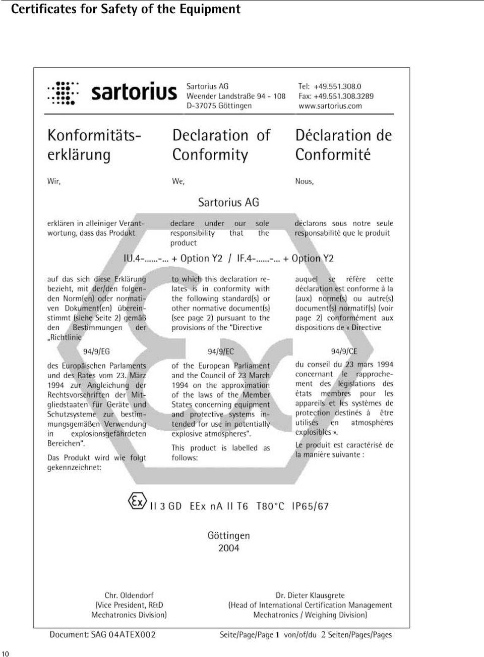
10 10 Certificates for Safety of the Equipment
11 11

12 1. Connecting the Weighing Platform to Equipment in a Hazardous Area Zone 2 or Zone 22 hazardous area Gas: Group II, temperature class T6 (all gases) Dust: Surface temperature of the equipment 80 C max. Ambient temperature: -20 C C 4) Indicator 3 (e.g., CIS.. with Option Y2) Shielded cable [w/ screen] for deflecting electrostatic charges IU with Option Y2 or IF with Option Y2 2) Alternative 2 1) 2. Connecting the Weighing Platform to Equipment Outside a Hazardous Area Non-hazardous area This equipment may also be installed in Zone 2 or 22 if it is suitable for Category 3 according to the ATEX Directive. Zone 2 or Zone 22 hazardous area Gas: Group II, temperature T6 (all gases) Dust: Surface temperature of the equipment 80 C max. Ambient temperature: -20 C ) External indicator or PC, etc. 2) Nominal power supply voltage: <= 15Vdc Shielded cable (with shield) for deflecting electrostatic charges IU with Option Y2 or IF with Option Y2 1) 2) 1: Equipotential bonding busbar 2: Connecting cable, cross section (gauge) at least 4 mm 2 3: Please follow the (Ex) installation instructions for this equipment 4: The temperature range may be restricted for operational reasons (please see Data Sheet for platform). Written by Reviewed by Released by Date Name Klausgrete Weitemeier Klausgrete Designation Drawing No. Installation Instructions A4 Revision 00 Page 1 of 3 12
 Dust: Surface temperature of the equipment 80 C max. Ambient temperature: -20 C.")
13 3. Static Electricity in Hazardous Areas Avoid generating static electricity: Pull the weighing platform slowly (< 1m/s) or connect a grounding cable Plastic rollers (included in standard equipment supplied) IU or IF Option: Grounding (earthing) cable suitable for hazardous areas; non-sparking; not included in standard equipment supplied Option: Grounding (earthing) cable suitable for hazardous areas; nonsparking; not included in standard equipment supplied Lifting mechanism: Rollers can be extended IF Avoid generating static electricity: Pull the weighing platform slowly (< 1m/s) or connect a grounding cable Plastic rollers Written by Reviewed by Released by Date Name Klausgrete Weitemeier Klausgrete Designation Drawing No. Installation Instructions A4 Revision 00 Page 2 of 3 13

14 Marking / Test certificate nos.: IU II 3 GD EEx na II T6 T80 C IP65/67 (*) IF II 3 GD EEx na II T6 T80 C IP65/67 (*) *: Manufacturer's declaration (Document SAG04ATEX002) Temperature range / Output parameters: IU C C (*) --- IF C C (*) --- *: The temperature range may be restricted for operational reasons (please see Data Sheet for platform). Instructions and information: 1) Install the equipment in compliance with applicable laws, rules and regulations, ordinances and standards. In particular, be sure to conform to the European Standards EN (Electrical apparatus for use in potentially explosive atmospheres) and EN (Electrical apparatus for use in the presence of combustible dust). 2) Be sure to follow the installation, operating, maintenance and servicing instructions given in the manuals supplied. 3) The cable glands must be secured so that they cannot work loose. 4) The housing of equipment connected to power may only be opened outside the hazardous area. 5) All metallic parts (housing, column, load plate, drive-on ramp, bench, etc.) must be electrically connected to the terminal for the equipotential bonding conductor so that any electrostatic charges can be conducted away from the equipment. 6) Avoid generating static electricity. Use only a damp cloth to wipe down the equipment. 7) If you wish to use other manufacturer's equipment in a Zone 2 hazardous area, be sure that it has the required group and temperature class; to use such equipment in Zone 22, make sure that this equipment has the maximum surface temperature specified. 8) If you plan to use the equipment in Zone 22: prevent a layer of dust of more than 5 mm from accumulating on the equipment. 9) Observe the installation instructions and information for equipment connected to the platform, such as A4 for ISI or QCT connections and A4 for connecting CIS. + Option Y2. Written by Reviewed by Released by Date Name Klausgrete Weitemeier Klausgrete Designation Drawing No. Installation Instructions A4 Revision 00 Page 3 of 3 14
 and EN 50281-1-2 (Electrical apparatus for use in the")
15 Übersichtsdarstellung Wägebrücke 2 Tragegriff 3 Libelle 4 Kabelanschlußkasten 5 Wägezelle mit Lastfuß 6 Transportrolle Wägeplattform 2 Halte- und Führungsgriffe 3 Libelle 4 Auffahrrampe 5 Wägezelle mit Lastfuß 6 Kabelanschlusskasten 15

16 Inhalt 13 Übersichtsdarstellung 14 Inhalt 14 Verwendungszweck 14 Sicherheits- und Warnhinweise 15 Aufstellhinweise 15 Installation 16 Anschluss der IUS... oder IFS Pflege und Wartung 18 Zertifikate für die Sicherheit der Waage Folgende Symbole werden in dieser Anleitung verwendet: steht vor Handlungsanweisungen $ steht vor Handlungsanweisungen, die nur unter bestimmten Voraussetzungen ausgeführt werden sollen > beschreibt das, was nach einer ausgeführten Handlung geschieht steht vor einem Aufzählungspunkt! Weist auf eine Gefahr hin! Verwendungszweck Die Wägeplattform ist Bestandteil einer modular aufgebauten Waage, bestehend aus der Wägeplattform und einem Auswertegerät (bestehend aus Analog- Digitalwandler, sowie Anzeige- und Bedieneinrichtung), z.b. Combics CIS2 CIS3. Für das jeweilige Auswertegerät gibt es eine separate Betriebsanleitung. Hinweis: Die eichfähigen Modelle -.CE sind nur in Verbindung mit einem Auswertegerät als Waage eichfähig! Bevor die IU../IF.. Wägeplattform angeschlossen und in Betrieb genommen wird, die Aufstell- und Betriebsanleitung aufmerksam durchlesen und aufbewahren. Sicherheits- und Warnhinweise Hinweis: Ein unsachgemäßer Gebrauch kann zu Schäden an Personen und Sachen führen. Die Modelle nur von qualifiziertem Personal installieren und betreiben. Die Sicherheits- und Warnhinweise in ihrer Gesamtheit bei der Installation, beim Betrieb, bei der Wartung und Reparatur des Gerätes befolgen. Normen, Verordnungen, sowie Unfallverhütung und den Umweltschutz des jeweiligen Landes befolgen und einhalten. Diese Hinweise sollten alle Beteiligten verstehen und die Dokumente stets griffbereit sein. Die Sicherheits- und Warnhinweise in den Unterlagen der angeschlossenen elektrischen Betriebsmittel wie z.b. Zubehör, befolgen. Diese Sicherheits- und Warnhinweise muss der Betreiber ggf. ergänzen. Das Bedienpersonal entsprechend einweisen. Die Einrichtungen immer frei zugänglich halten! Allgemeine Bestimmungen für die Installation der Modelle IUS.., IUS...CE, IFS.. und IFS...CE Das Modell IUS.., IUS...CE, IFS.. oder IFS...CE erfüllt die Anforderungen der EG-Richtlinie 94/9/EG für Geräte der Gerätegruppe III, und sind geeignet für den Einsatz in den explosionsgefärhdeten Bereichen der Zonen 2 und 22 gemäß Herstellerklärung: SAG.04.ATEX.002. Ferner erfüllt das Modell IUS.., IUS...CE, IFS.. oder IFS...CE die Anforderungen der EG-Richtlinien für elektromagnetische Verträglichkeit und elektrische Sicherheit. Der Einsatzbereich der IUS.., IUS...CE, IFS.. oder IFS...CE ist in der Herstellerklärung definiert. Alle in der Herstellerklärunggenannten Beschränkungen sind einzuhalten. Ein Betrieb der IUS.., IUS...CE, IFS.. oder IFS...CE über die Beschränkungen hinaus ist nicht zulässig und gilt als nicht bestimmungsgemäßer Gebrauch. Bei unsachgemäßer Installation entfällt die Gewährleistung. Bei einem Einsatz des Gerätes in explosionsgefährdeten Bereichen der Zone 2 und 22 sind die nationalen Gesetzte/Vorschriften und Normen einzuhalten (z.b.: EN für Gas und EN für Staub). Den Lieferanten nach den in Ihrem Land geltenden Bestimmungen befragen. Sartorius kennzeichnet durch die angebrachten Siegelmarken den einwandfreien Zustand des Produktes. Bei der Installation oder Wartung durch von Sartorius geschulte und autorisierte Servicetechniker wird das Gerät anschließend wieder versiegelt. Bei zerstörten Siegelmarken übernimmt die Sartorius AG keine Garantie. Die Installation des Auswertegeräts muss von einer Elektrofachkraft erfolgen. Als Fachkraft gilt eine Person, die mit der Montage, Inbetriebnahme und Betrieb der Anlage vertraut ist. Die Elektrofachkraft verfügt über die entsprechende Qualifikation, die einschlägigen Bestimmungen und Vorschriften sind Ihr bekannt. Bei Bedarf den Händler oder Sartorius Kundendienst ansprechen. Elektrostatische Aufladung vermeiden. Die Wägeplattform ist über den Schirm des Verbindungskabels mit dem Auswertegerät verbunden. Potentialausgleichsklemme anschließen. Eine Unterbrechung der Potentialausgleichsleitungen ist untersagt. Die Erdung erfolgt über einen Gewindebolzen, eine Schraubklemme oder ist als Bohrung (M6) vorhanden. Die Stelle ist mit einem Erdungssymbol gekennzeichnet. Bei der Bohrung die Erdung mit einer Edelstahlschraube vornehmen. Zum Schutz vor Selbstlösen sollte eine Zahnscheibe untergelegt sein. Das Erdungskabel muss einen Mindestquerschnitt von 4 mm 2 haben und mit einer geeigneten Ringöse ausgestattet sein. Alle Geräte und Zubehörteile mit dem Potentialausgleich (PA) verbinden. Wird die Wägeplattform im Explosionsgefährdeten Bereich bewegt, gezogen: Schritttempo <1m/s, alternativ ein optionales Erdungskabel anschließen. Für den Benutzer Wartungs-, Reinigungs- und Reparaturarbeiten an der Waage sind grundsätzlich im spannungsfreiem Zustand der errichteten Anlage durchzuführen. Erscheint Ihnen ein gefahrloser Betrieb nicht mehr gewährleistet, die Waage von der Betriebsspannung trennen und gegen weitere Benutzung sichern (z.b. bei einer Beschädigung). Hinweis: Wenn die Waage geeicht wird (eichfähig ist nur die komplette Waage, d.h.: IUS.., IUS...CE, IFS.. oder IFS...CE Wägeplattform in Verbindung mit einem Auswertegerät/Indicator (Analog-/Digitalwandler, z.b.: Indicator CIS3), weisen die angebrachten Siegelmarken darauf hin, dass die Waage nur durch geschulte und autorisierte Fachkräfte geöffnet und gewartet werden darf. Der einwandfreie und sichere Betrieb ist dann gewährleistet. Bei zerstörten Siegelmarken erlischt die Eichgültigkeit. Die nationalen Gesetze und Vorschriften einhalten. In Deutschland ist eine Nacheichung durch das Eichamt erforderlich. Chemikalien (zb.: Gase, Flüssigkeiten oder Stäube), die die Geräte oder Kabel innen oder aussen angreifen und beschädigen können, sind fernzuhalten. Der IP Schutz des Gerätes und des Zubehörs (ab IP 65) einhalten, (DIN EN 60529). Die Ummantelung aller Verbindungskabel, sowie die der Litzen der inneren Verdrahtungen bestehen aus PVC-Material. Verkabelung: Die Ummantelung des Netzkabels besteht aus Gummi. Die Waage/Wägeanlage nicht unnötig extremen Temperaturen, aggressiven chemischen Dämpfen, Feuchtigkeit, Stößen und Vibrationen aussetzen. Die zulässige Umgebungstemperatur im Betrieb beträgt 20 C bis +40 C, bei geeichten Geräten -10 C bis +40 C. Eine gute Belüftung der Geräte ist erforderlich um Wärmestau zu vermeiden. Bei Verwendung fremdbezogener Kabel auf die Pinbelegungen achten. Die Anschlüsse des Kabels deshalb vor Anschluss an Sartorius Geräte nach dem entsprechenden Verbindungsplan prüfen und die abweichend belegten Leitungen trennen. Nicht von Sartorius gelieferte Kabel unterliegen der Verantwortung des Betreibers. Nur original Sartorius-Ersatzteile verwenden! 16

17 Aufstellhinweise Installation Auspacken Die beiliegende Betriebsanleitung vor Inbetriebnahme aufmerksam durchlesen. Das Gerät sofort nach dem Auspacken auf eventuell sichtbare äussere Beschädigungen überprüfen $ Im Beschädigungsfall Kapitel»Pflege und Wartung«, Abschnitt»Sicherheitsüberprüfung«beachten $ Alle Teile der Verpackung für einen eventuell notwendigen Versand aufbewahren, denn nur die Originalverpackung gewährleistet sicheren Transport $ Vor dem Versand alle angeschlossenen Kabel trennen, um unnötige Beschädigungen zu vermeiden Lieferumfang Wägeplattform IUS.. oder IFS.. Aufstell- und Betriebsanleitung (incl. Herstellerklärung) Installation und Sicherheitshinweise Anforderungen an den Aufstellort Die Sicherheits- und Warnhinweise befolgen! Die IUS.. oder IFS.. ist so konstruiert, dass unter den im Betrieb üblichen Einsatzbedingungen zuverlässige Wägeergebnisse erzielt werden. Exakt und schnell arbeitet die IUS.. oder IFS.., wenn der richtige Standort gewählt ist: IUS.. oder IFS.. auf eine stabile, gerade Fläche stellen. Die Bodenbelastung muss für die Wägeplattform und deren Belastung ausreichen. Das Gerät in Libelle stellen. extreme Wärme durch Aufstellen neben der Heizung oder direkte Sonneneinstrahlung vermeiden IIUS.. oder IFS..vor direktem Luftzug schützen (geöffnete Fenster und Türen) starke Erschütterungen vermeiden IUS.. oder IFS..vor aggressiven chemischen Dämpfen schützen extreme Feuchte vermeiden. Bei Nichtgebrauch ist die Anlage auszuschalten Der Arbeitstemperaturbereich liegt zwischen 20 C und +40 C, bei geeichten Geräten 10 C bis +40 C. Zeigen sich bei dieser Inbetriebnahme durch Transportschäden Abweichungen (keine Anzeige, keine Hinterleuchtung an dem Auswertegerät, so ist die Anlage vom Netz zu trennen und der Service zu informieren, siehe:»pflege und Wartung«, Abschnitt»Sicherheitsüberprüfung«Schockbelastbarkeit Die IUS.. oder IFS..-Modelle sind robust konstruiert, aber fallende Wägegüter, seitliche Stöße und Schockbelastungen sollten vermieden werden. Hinweise zum Planen von Aufbauten Bewegte oder rotierende Teile auf der IUS.. oder IFS.. müssen so gestaltet sein, dass sie das Wägeergebnis nicht beeinflussen können. Rotierende Teile sind z.b. auszuwuchten. Die IUS.. oder IFS.. muss beim Wägen auf allen Seiten frei sein, so dass durch herabfallende Teile oder Schmutz keine Verbindung zwischen der Lastplatte und fest montierten Teilen entsteht. Kabel oder andere Gegenstände dürfen keine Kräfte auf die Lastplatte ausüben. Elektrostatische Aufladung vermeiden. Einsatz der IUS...CE oder IFS...CE im eichpflichtigen Verkehr Die Bauartzulassung zur Eichung gilt nur für nichtselbsttätige Waagen. Für selbsttätigen Betrieb mit oder ohne zusätzlich angebauten Zusatzeinrichtungen die für den Aufstellort geltenden nationalen Vorschriften einhalten. Die Wägeanlage akklimatisieren Eine Betauung kann auftreten (Kondensation von Luftfeuchtigkeit am Gerät), wenn ein kaltes Gerät in eine wesentlich wärmere Umgebung gebracht wird. Das vom Netz getrennte Gerät ca. 2 Stunden bei Raumtemperatur akklimatisieren. Das Gerät ständig am Netz lassen. Durch die dauernde positive Temperaturdifferenz zwischen Geräteinnenraum und Umgebung ist dann ein Feuchteeinfluss nahezu auszuschließen. Hinweis: Der Anschluss des Auswertegerätes, Aufstellung, Konfiguration, Inbetriebnahme, und Ersteinweisung darf nur durch geschulte Händler oder Sartorius- Kundendienstmitarbeiter erfolgen! Zu weiteren Einstellungen wird das Sartorius Service Handbuch benutzt. Nicht unter Spannung am Gerät arbeiten! Die Installationsarbeiten nur mit Spezialwerkzeug durchführen! IP65- oder IP68-Schutz beeinflussende Arbeiten sind äußerst sorgfältig durchzuführen! Bei unsachgemäßer Installation entfällt die Gewährleistung. bei Einbau in Wägeanlagen ist die Maschinenrichtlinie (98/37/EG) zu beachten. Das Gerät in Libelle stellen. Die Einstellung der Libelle erfolgt mit den Lastfüßen. Die Wägeplattform am Aufstellort mit den Lastfüßen so ausrichten, dass die Luftblase der Libelle in Kreismitte steht. Prüfen, ob alle 4 Lastfüßen Bodenkontakt haben. Hinweis: Eine einwandfreie Masseverbindung zwischen dem Auswertegerät und der Plattform einhalten (Widerstand <1 Ohm). Der Schirm muss mit der Kabel- Verschraubung am Auswertegerät und mit der Kabel-Verschraubung an der Junctionbox verbunden werden. IP68-Schutz bei Edelstahl Ausführung Nach Schutzart IP68 ist die Wägeplattform Staubdicht: (erste Ziffer = 6: Gegen das Eindringen von Staubteilchen) und Wasserdicht: (zweite Ziffer = 8: Gegen das Eindringen von Wasser beim Untertauchen bis 10 Meter). Der IP68-Schutz ist nur gewährleistet bei: fachgerecht eingebauter Dichtung am Klemmanschlusskasten fachgerechter Verlegung, Installation und Verbindung der Anschlussleitungen und Kabel- Verschraubungen. Kennzeichnungsschilder der Modelle IUS...CE und IFS...CE anbringen Je nach Konfiguration der Waage sind entsprechende Kennzeichnungsschilder vor der Ersteichung erforderlich. Die Schilder sind auf dem Auswertegerät oder in besonderen Fällen auf dem hierfür vorgesehenen Kennzeichnungsschildträger anzubringen. Der Kennzeichnungsschildträger befindet sich, wenn benötigt, im Lieferumfang des Auswertegerätes. Der Kennzeichnungsschildträger wird an dem Verbindungskabel zwischen der IUS..CE oder IFS..CE und Auswertegerät befestigt. Netzanschluss Die Stromversorgung erfolgt über das Verbindungskabel des Auswertegerätes. 17

18 Aufstellhinweise Auspacken Die beiliegende Betriebsanleitung vor Inbetriebnahme aufmerksam durchlesen. Das Gerät sofort nach dem Auspacken auf eventuell sichtbare äußere Beschädigungen überprüfen. Holzpalette oben öffnen. $ Die Waage soll komplett aus der Holzpalette herausgehoben werden. Hinweis: Die höhenverstellbaren Lastfüße sind bereits für eine ebene Bodenfläche ab Werk eingestellt! Eine unsachgemäße Handhabung der Waage kann zu Beschädigungen der Bauteile führen. Die Sicherheit des Gerätes ist dann eingeschränkt. Sicherheitshinweise befolgen! Gurte einhängen: Vorne um die Haltegriffe. Waage gleichmäßig am Aufstellort absetzen. $ Der Aufstellort muss sauber, eben und für die Aufnahme der Last (Druckbelastung) geeignet sein. Bodenunebenheiten entfernen. Waage am Aufstellort nach Libelle ausrichten, Bodenrahmen auf Winkeligkeit prüfen. Winkeligkeit einhalten! Zur Kontrolle die Diagonalen messen. Dübellöcher für die Befestigungsanker (im Lieferumfang) anzeichnen. 8+ Befestigungsanker: M 10-15/85 Den Aufstellort frei machen. Waage gleichmäßig anheben.!nicht unter die Last treten, es besteht Verletzungsgefahr! Sicherheitshinweise befolgen! Ankerlöcher (M10) in die Markierungen bohren. Mindesttiefe: 65 mm. Tiefe prüfen, Bohrstaub aus den Bohrungen entfernen (ggf. ausblasen). Aufstellort reinigen. Hinten um den Mitnehmerrahmen. Waage wieder vorsichtig auf den Aufstellort aufsetzen. Die Waage an den Bohrungen mit dem Bodenrahmen zur Deckung bringen. Waage am Aufstellort nach Libelle ausrichten, Bodenrahmen auf Winkeligkeit prüfen. Winkeligkeit einhalten! Zur Kontrolle die Diagonalen messen. Waage gleichmäßig anheben. Waage an den Aufstellort bringen.!nicht unter die Last treten, es besteht Verletzungsgefahr! Sicherheitshinweise befolgen! Die Waage befestigen: Die Befestigungsanker in die Bohrlöcher einschlagen. Die Schrauben anziehen: M10 (SW:17). Die Distanz der Niederhalter (rechts und links) kontrollieren: jeweils ein 2 mm starkes Distanzblech unterlegen, oder die Distanz messen. $ Die Distanz: 2 mm in regelmäßigen Abständen prüfen. 18
 geeignet sein.")
19 Den Abstand: 2 mm einstellen. Wenn nötig, die Schrauben des Niederhalters lösen: Befestigungsschrauben: M 8 (SW: 13) Bevor die Plattform der Waage in die vertikale Position geklappt werden kann, die Rastbolzen (rechts und links) lösen.! Beschädigungsgefahr der Rastbolzen! Die hinteren Rastbolzen dürfen nicht eingerastet sein! Die Plattform an den Haltegriffen fassen und in die vertikale Position stellen. Hinweis: Die Plattform nur mit zwei Personen in die vertikale Position bringen!!sicherheitshinweise beachten, es besteht Verletzungsgefahr. Sicherheitsschuhe tragen. Nach dem Einbau die Plattform wieder in die horizontale Lage klappen. Hintere Rastbolzen (recht und links) umlegen. Der Bolzen fährt aus der Wange und gibt die Plattform frei.! Beschädigungsgefahr der Rastbolzen! Die vorderen Rastbolzen dürfen nicht eingerastet sein! Die Plattform an den Haltegriffen fassen und in die horizontale Position stellen. Hinweis: Die Plattform nur mit zwei Personen in die horizontale Position bringen!! Sicherheitshinweise beachten, es besteht Verletzungsgefahr. Sicherheitsschuhe tragen. Nicht unter die Plattform treten! Die Plattform befindet sich in der horizontalen Position. Mit dem Fuß auf den Niederhalter treten (rechts und links), die Wangen der Waagen auf den Boden drücken.! Verletzungsgefahr! Nicht unter die Plattform treten! Mit den vorderen Rastbolzen (rechts und links) die Plattform fixieren, Hebel umlegen. Rastbolzen (recht und links) umlegen. Der Bolzen fährt in die Wange und sichert die Plattform in der vertikalen Stellung. Montagehilfe (rechts und links) demontieren: Die Schrauben heraus drehen: 4 + M8 (SW:13). $ Die Fläche unter der Plattform kann jetzt auch problemlos gereinigt werden. Gasdruckfedern (rechts und links) nach Abbildung einbauen. Die Schrauben anziehen: M10 (SW:17). Die Auffahrrampe rechts und links in die Vorrichtung einhängen. 19

20 Anschluss der IUS.. oder IFS.. Verbindungskabel IUS.. oder IFS.. zum Auswertegerät Kabel, Typ: A oder Kabel, Typ: B V + (Versorgungsspannung +) (Weiss) oder Blau V (Versorgungsspannung -) (Braun) oder Schwarz Signal + (Ausgangssignal +) (Grün) oder Weiss Signal (Ausgangssignal -) (Gelb) oder Rot Sense + (Schirmleitung +) (Rosa) oder Grün Sense (Schirmleitung -) (Grau) oder Grau Masse (Schirm) Bodenfixierung der IFS4... (Option T8) Die beiliegenden Bodenanker für die Sondermodelle entnehmen. Das Gerät an den gewünschten Aufstellort bringen. $ Die Flachstähle parallel ausrichten. Die Markierungen zum Bohren der Löcher anbringen. Die Löcher für die Bodenanker anbohren. Das Gerät verschieben, die Löcher für die Bodenanker bohren. Die Fläche sorgfältig säubern! Das Gerät über die Bohrungen schieben und mit den Bodenankern fixieren. $ Eine Verspannung des Gerätes vermeiden! Das Gerät kann jetzt verschoben werden, (Schritttempo <1 m/s) Sicherheitshinweise beachten! Wenn eine Deichsel (Option) vorhanden ist, die Deichsel einhängen. Transport der IFS4... (Option T8) Die Rampe vor der Lastplatte entfernen. Die Lastplatte muss unbelastet sein! $ Sicherheitshinweise beachten! $ Das Gerät kann jetzt gezogen werden, (Schritttempo <1 m/s) Sicherheitshinweise beachten! $ Der Untergrund unter der Wägeplattform kann jetzt gereinigt werden. Die vier Gewindeabdeckungen abschrauben und aufbewahren. $ Die Gewindestangen gängig halten, Gewindestangen regelmäßig einfetten! Das Gerät an den Aufstellort bringen, die Räder einfahren. Handkurbeln abnehmen. Die vier Gewindeabdeckungen aufschrauben. Die zwei Handkurbeln auf die vorderen Gewinde schrauben. Im Uhrzeigersinn drehen, die Räder des Gerätes werden ausgefahren. $ Den Vorgang für die hinteren Räder wiederholen. Achtung: Die Plattform muss unbelastet sein. Die Rampe vor die Lastplatte einhängen. $ Sicherheitshinweise beachten! 20
 (Gelb) oder Rot Sense + (Schirmleitung +) (Rosa) oder Grün Sense (Schirmleitung -) (Grau) oder Grau Masse (Schirm) Bodenfixierung der IFS4.")
Notice Technique / Technical Manual
 Contrôle d accès Access control Encodeur USB Mifare ENCOD-USB-AI Notice Technique / Technical Manual SOMMAIRE p.2/10 Sommaire Remerciements... 3 Informations et recommandations... 4 Caractéristiques techniques...
Fabricant. 2 terminals
 Specifications Fabricant Nominal torque (Nm) 65 Minimal torque (Nm) 0,63 Coil resistance - 20 C (ohms) 20 Rated current DC (A) 1 Rotor inertia (kg.m 2 ) 2.10-3 Weight (kg) 7,20 Heat dissipation continuous
Lavatory Faucet. Instruction Manual. Questions? 1-866-661-9606 customerservice@artikaworld.com
 Lavatory Faucet Instruction Manual rev. 19-01-2015 Installation Manual You will need Adjustable Wrench Adjustable Pliers Plumber s Tape Hardware list (included) Allen Key Socket wrench tool Important Follow
R.V. Table Mounting Instructions
 PTSS165 ACCESSORY MOUNTING INSTRUCTIONS Use these instructions in conjunction with your main manual to properly assemble your gas grill. Refer to the main manual for safety, operating, cleaning and maintenance
ASSEMBLY INSTRUCTIONS DIRECTIVES POUR L'ASSEMBLAGE ombre pendant lamp lampe suspendue à tons dégradés, chocolat
 ASSEMBLY INSTRUCTIONS DIRECTIVES POUR L'ASSEMBLAGE ombre pendant lamp lampe suspendue à tons dégradés, chocolat SKU 2728089 INSTRUCTIONAL MANUAL MANUEL D'INSTRUCTIONS 270/2707 COMPONENT LIST LISTE DES
ASSEMBLY INSTRUCTIONS DIRECTIVES POUR L'ASSEMBLAGE luster chandelier lamp chandelier à trois branches en verre lustré
 ASSEMBLY INSTRUCTIONS DIRECTIVES POUR L'ASSEMBLAGE luster chandelier lamp chandelier à trois branches en verre lustré SKU 2711592 INSTRUCTIONAL MANUAL MANUEL D'INSTRUCTIONS 270/2707 COMPONENT LIST LISTE
Your Pirelli VDSL router has been preconfigured with the following settings:
 Important Information & Installation Instructions VDSL (Analog) Dear Netstream customer Your Pirelli VDSL router has been preconfigured with the following settings: LAN IP Adress of the Pirelli router:
Mesure chimique. Chemical measurement. Sonde de température Pt 1000 Inox Pt 1000 stainless steel. Ref : 703 262. Français p 1.
 Mesure chimique Chemical measurement Français p 1 English p 3 Sonde de température Pt 1000 Inox Pt 1000 stainless steel Version : 6010 Mesure chimique Sonde de température Pt 1000 Inox 1 Description La
Paxton. ins-20605. Net2 desktop reader USB
 Paxton ins-20605 Net2 desktop reader USB 1 3 2 4 1 2 Desktop Reader The desktop reader is designed to sit next to the PC. It is used for adding tokens to a Net2 system and also for identifying lost cards.
APPENDIX 6 BONUS RING FORMAT
 #4 EN FRANÇAIS CI-DESSOUS Preamble and Justification This motion is being presented to the membership as an alternative format for clubs to use to encourage increased entries, both in areas where the exhibitor
DOCUMENTATION - FRANCAIS... 2
 DOCUMENTATION MODULE SHOPDECORATION MODULE PRESTASHOP CREE PAR PRESTACREA INDEX : DOCUMENTATION - FRANCAIS... 2 INSTALLATION... 2 Installation automatique... 2 Installation manuelle... 2 Résolution des
03/2013. Mod: WOKI-60IP/TR. Production code: DTWIC 6000
 03/2013 Mod: WOKI-60IP/TR Production code: DTWIC 6000 ENCASTRABLE INDUCTION DROP IN INDUCTION 11/2011 TECHNICAL FEATURES DOCUMENTATION S.A.V. Notice d utilisation : FX00326-A Guide d intervention : ---
Typ 511. Serrure de vitrine 6005 pour portes coulissantes en verre, zamak, nickelé au mat.
 Knopfzylinder 6005 für Glas-Schiebetüren,Vitrinen etc., Zamak, matt vernickelt. Cylinder knob 6005 for glass sliding doors, die-cast, dull nickel-plated. Serrure de vitrine 6005 pour portes coulissantes
Guide d'installation rapide TFM-560X YO.13
 Guide d'installation rapide TFM-560X YO.13 Table of Contents Français 1 1. Avant de commencer 1 2. Procéder à l'installation 2 Troubleshooting 6 Version 06.08.2011 16. Select Install the software automatically
Warning: Failure to follow these warnings could result in property damage, or personal injury.
 Western Steel & Tube 1 Storage Locker Extended Storage Locker Storage Cabinet Assembly And Use Instructions Warning: Failure to follow these warnings could result in property damage, or personal injury.
1. Raison de la modification
 T Service Documentation Technicocommerciale Information Technique Rubrique F Les régulations Nouvelle version de programme de la carte SU : F1.4 P5253 JS F 67580 Mertzwiller N ITOE0117 26/09/2011 FR 1.
Thank you for choosing the Mobile Broadband USB Stick. With your USB Stick, you can access a wireless network at high speed.
 Thank you for choosing the Mobile Broadband USB Stick. With your USB Stick, you can access a wireless network at high speed. Note: This manual describes the appearance of the USB Stick, as well as the
Contrôle d'accès Access control. Notice technique / Technical Manual
 p.1/18 Contrôle d'accès Access control INFX V2-AI Notice technique / Technical Manual p.2/18 Sommaire / Contents Remerciements... 3 Informations et recommandations... 4 Caractéristiques techniques... 5
Instructions Mozilla Thunderbird Page 1
 Instructions Mozilla Thunderbird Page 1 Instructions Mozilla Thunderbird Ce manuel est écrit pour les utilisateurs qui font déjà configurer un compte de courrier électronique dans Mozilla Thunderbird et
GIGABIT PCI DESKTOP ADAPTER DGE-530T. Quick Installation Guide+ Guide d installation+
 GIGABIT PCI DESKTOP ADAPTER Quick Installation Guide+ Guide d installation+ Check Your Package Contents Quick Installation Guide Gigabit Ethernet PCI Adapter CD with Manual and Drivers DO NOT insert the
Thank you for choosing the Mobile Broadband USB Stick. With your USB Stick, you can access a wireless network at high speed.
 Thank you for choosing the Mobile Broadband USB Stick. With your USB Stick, you can access a wireless network at high speed. Note: This manual describes the appearance of the USB Stick, as well as the
POLICY: FREE MILK PROGRAM CODE: CS-4
 POLICY: FREE MILK PROGRAM CODE: CS-4 Origin: Authority: Reference(s): Community Services Department Cafeteria Services and Nutrition Education Division Resolution #86-02-26-15B.1 POLICY STATEMENT All elementary
ASSEMBLYcomponents H 10. Grundplatte. Base plate. Plaque de base BEM 3 BEW 3. FP 3 Base plate 30001121 1,1kg BEM 6 BEM 6D BEW 6
 S ASSEMBLYcomponents Base plate FP H 10 Die Grundplatten sind aus Stahl 700 N/mm 2 hergestellt. Sie sind brüniert und beidseitig geschliffen. Die Passfedern werden mitgeliefert. Die SUHNER-Bearbeitungseinheiten
DOCUMENTATION - FRANCAIS... 2
 DOCUMENTATION MODULE CATEGORIESTOPMENU MODULE CREE PAR PRESTACREA INDEX : DOCUMENTATION - FRANCAIS... 2 INSTALLATION... 2 CONFIGURATION... 2 LICENCE ET COPYRIGHT... 3 SUPPORT TECHNIQUE ET MISES A JOUR...
Z-Axis Compliance Device Compliance en z
 Compensation for different vertical positions Collision recognition in Z-direction Protection of parts and work pieces Monitoring of the insertion forces during assembly operations Monitoring of the picking
First Nations Assessment Inspection Regulations. Règlement sur l inspection aux fins d évaluation foncière des premières nations CONSOLIDATION
 CANADA CONSOLIDATION CODIFICATION First Nations Assessment Inspection Regulations Règlement sur l inspection aux fins d évaluation foncière des premières nations SOR/2007-242 DORS/2007-242 Current to September
Règlement sur le télémarketing et les centres d'appel. Call Centres Telemarketing Sales Regulation
 THE CONSUMER PROTECTION ACT (C.C.S.M. c. C200) Call Centres Telemarketing Sales Regulation LOI SUR LA PROTECTION DU CONSOMMATEUR (c. C200 de la C.P.L.M.) Règlement sur le télémarketing et les centres d'appel
Contents Windows 8.1... 2
 Workaround: Installation of IRIS Devices on Windows 8 Contents Windows 8.1... 2 English Français Windows 8... 13 English Français Windows 8.1 1. English Before installing an I.R.I.S. Device, we need to
TABLE DES MATIERES A OBJET PROCEDURE DE CONNEXION
 1 12 rue Denis Papin 37300 JOUE LES TOURS Tel: 02.47.68.34.00 Fax: 02.47.68.35.48 www.herve consultants.net contacts@herve consultants.net TABLE DES MATIERES A Objet...1 B Les équipements et pré-requis...2
How to Login to Career Page
 How to Login to Career Page BASF Canada July 2013 To view this instruction manual in French, please scroll down to page 16 1 Job Postings How to Login/Create your Profile/Sign Up for Job Posting Notifications
Garage Door Monitor Model 829LM
 Garage Door Monitor Model 829LM To prevent possible SERIOUS INJURY or DEATH from a closing garage door: NEVER permit children to operate or play with door control push buttons or remote control transmitters.
MODE D EMPLOI USER MANUAL
 notice_cd 853:notice 9/01/08 15:08 Page 1 CAFETIÈRE À DOSETTES Coffee pad machine CD 853 GIACOMO MODE D EMPLOI USER MANUAL notice_cd 853:notice 9/01/08 15:08 Page 2 FRANÇAIS WHITE & BROWN vous félicite
WINTER BOAT STORAGE SYSTEM SYSTÈME DE REMISAGE HIVERNAL POUR BATEAU
 MANUAL / MANUEL VIDEO WINTER BOAT STORAGE SYSTEM SYSTÈME DE REMISAGE HIVERNAL POUR BATEAU ASSEMBLY INSTRUCTIONS GUIDE D ASSEMBLAGE NAVIGLOO 14-18½ ft/pi FISHING BOAT! RUNABOUT! PONTOON BOAT! SAILBOAT (SAILBOAT
SYSTÈME JETS D AIR WISH WISH AIR JETS SYSTEM Système de massage à jets d air pour bains en polymère - Air jet massage system for polymer bathtubs
 SYSTME JETS D AIR WISH WISH AIR JETS SYSTEM Système de massage à jets d air pour bains en polymère - Air jet massage system for polymer bathtubs Manuel d installation - Installation manual 6835, RUE PICARD
APPENDIX 2. Provisions to be included in the contract between the Provider and the. Holder
 Page 1 APPENDIX 2 Provisions to be included in the contract between the Provider and the Obligations and rights of the Applicant / Holder Holder 1. The Applicant or Licensee acknowledges that it has read
Betriebsanleitung Programmierkabel PRKAB 560 Mode d emploi Câble de programmation PRKAB 560 Operating Instructions Programming cable PRKAB 560
 Betriebsanleitung Programmierkabel Câble de programmation Operating Instructions Programming cable B d-f-e 146 599-02 03.06 Camille Bauer AG Aargauerstrasse 7 CH-5610 Wohlen/Switzerland Telefon +41 56
Folio Case User s Guide
 Fujitsu America, Inc. Folio Case User s Guide I N S T R U C T I O N S This Folio Case is a stylish, lightweight case for protecting your Tablet PC. Elastic Strap Pen Holder Card Holders/ Easel Stops Figure
Package Contents. System Requirements. Before You Begin
 Package Contents DWA-125 Wireless 150 USB Adapter CD-ROM (contains software, drivers, and manual) Cradle If any of the above items are missing, please contact your reseller. System Requirements A computer
Stainless Steel Solar Wall Light
 V 2.9 Stainless Steel Solar Wall Light User Manual Please read and understand all instructions before use.retain this manual for future reference. V 2.9 Stainless Steel Solar Wall Light SPECIFICATIONS
accidents and repairs:
 accidents and repairs: putting the pieces together accidents et réparations : réunir le tout nobody can repair your Toyota like Toyota Unfortunately, accidents do happen. And the best way to restore your
that the child(ren) was/were in need of protection under Part III of the Child and Family Services Act, and the court made an order on
 was/were in need of protection under Part III of the Child and Family Services Act, and the court made an order on") ONTARIO Court File Number at (Name of court) Court office address Applicant(s) (In most cases, the applicant will be a children s aid society.) Full legal name & address for service street & number, municipality,
ONTARIO Court File Number at (Name of court) Court office address Applicant(s) (In most cases, the applicant will be a children s aid society.) Full legal name & address for service street & number, municipality,
ETABLISSEMENT D ENSEIGNEMENT OU ORGANISME DE FORMATION / UNIVERSITY OR COLLEGE:
 8. Tripartite internship agreement La présente convention a pour objet de définir les conditions dans lesquelles le stagiaire ci-après nommé sera accueilli dans l entreprise. This contract defines the
Commutateur clavier-écran-souris 2/4 ports DKVM-2/4. Guide d utilisation. Rév. 1.3
 Commutateur clavier-écran-souris 2/4 ports DKVM-2/4 Guide d utilisation Rév. 1.3 Table des matières Introduction...1 Fonctionnalités...2 Contenu de l emballage...2 Installation du matériel...3 Face avant...
INDIVIDUALS AND LEGAL ENTITIES: If the dividends have not been paid yet, you may be eligible for the simplified procedure.
 Recipient s name 5001-EN For use by the foreign tax authority CALCULATION OF WITHHOLDING TAX ON DIVIDENDS Attachment to Form 5000 12816*01 INDIVIDUALS AND LEGAL ENTITIES: If the dividends have not been
Le No.1 de l économie d énergie pour patinoires.
 Le No.1 de l économie d énergie pour patinoires. Partner of REALice system Economie d énergie et une meilleure qualité de glace La 2ème génération améliorée du système REALice bien connu, est livré en
AMENDMENT TO BILL 32 AMENDEMENT AU PROJET DE LOI 32
 THAT the proposed clause 6(1), as set out in Clause 6(1) of the Bill, be replaced with the following: Trustee to respond promptly 6(1) A trustee shall respond to a request as promptly as required in the
LOGICIEL D'ADMINISTRATION POUR E4000 & G4000 MANAGEMENT SOFTWARE FOR E4000 & G4000
 LOGICIEL D'ADMINISTRATION POUR E4000 & G4000 MANAGEMENT SOFTWARE FOR E4000 & G4000 TABLE DES MATIÈRES TITRE PAGE Présentation - - - - - - - - - - - - - - - - - - - - - - - - - - - - - - - - - - - -4 Le
Principe de TrueCrypt. Créer un volume pour TrueCrypt
 Sommaire : Principe de TrueCrypt...1 Créer un volume pour TrueCrypt...1 Premier montage...6 Réglages...8 Save Currently Mounted Volumes as Favorite...8 Settings > Preferences...9 TrueCrypt Traveller pour
SA-32 / SA-62 INSTRUCTION MANUAL - MANUEL D INSTRUCTIONS
 SA-32 / SA-62 INSTRUCTION MANUAL - MANUEL D INSTRUCTIONS 4 5 6 7 4 5 6 7 1. Telephone Paging Volume Control 1. Contrôle de volume Paging Téléphone 2. Microphone Volume Control 2. Contrôle volume du microphone
ARP-090G / ARP-090K NOTICE D'EMPLOI INSTRUCTION MANUAL
 2 7 NOTICE D'EMPLOI INSTRUCTION MANUAL ARP-090G / ARP-090K Lire attentivement la notice avant d utiliser l appareil Before operating this product, please read user manual completely FRANCAIS EMPLACEMENT
Natixis Asset Management Response to the European Commission Green Paper on shadow banking
 European Commission DG MARKT Unit 02 Rue de Spa, 2 1049 Brussels Belgium markt-consultation-shadow-banking@ec.europa.eu 14 th June 2012 Natixis Asset Management Response to the European Commission Green
Sécurité relative aux sièges auto et aux rehausseurs
 Sécurité relative aux sièges auto et aux rehausseurs Safety with Car Seats and Booster Seats Car crashes are the main cause of accidental death and serious injury of children. Correctly using a car or
NEW Fin Fan / Air cooled condenser cleaning
 Air cooled Condensers ( ACC ) Cleaning Air Cooled heat exchangers ( Finfan) Cleaning Cleaning Services Permanente installation NEW Fin Fan / Air cooled condenser cleaning New and revolutionnary high pressure
Quick Installation Guide TEW-AO12O
 Quick Installation Guide TEW-AO12O Table of of Contents Contents Français... 1 1. Avant de commencer... 1 2. Installation du matériel... 2 3. Montage... 4 Troubleshooting... 6 Version 10.04.2007 1. Avant
Nouveautés printemps 2013
 » English Se désinscrire de la liste Nouveautés printemps 2013 19 mars 2013 Dans ce Flash Info, vous trouverez une description des nouveautés et mises à jour des produits La Capitale pour le printemps
Cheque Holding Policy Disclosure (Banks) Regulations. Règlement sur la communication de la politique de retenue de chèques (banques) CONSOLIDATION
 Regulations. Règlement sur la communication de la politique de retenue de chèques (banques) CONSOLIDATION") CANADA CONSOLIDATION CODIFICATION Cheque Holding Policy Disclosure (Banks) Regulations Règlement sur la communication de la politique de retenue de chèques (banques) SOR/2002-39 DORS/2002-39 Current to
CANADA CONSOLIDATION CODIFICATION Cheque Holding Policy Disclosure (Banks) Regulations Règlement sur la communication de la politique de retenue de chèques (banques) SOR/2002-39 DORS/2002-39 Current to
Guide d installation Deco Drain inc. DD200
 Guide d installation Deco Drain inc. DD200 Pour plus informations et pour télécharger les guides d installation en couleur, visitez notre site web. www.decodrain.com Soutien technique : Composez le : 514-946-8901
CEPF FINAL PROJECT COMPLETION REPORT
 CEPF FINAL PROJECT COMPLETION REPORT I. BASIC DATA Organization Legal Name: Conservation International Madagascar Project Title (as stated in the grant agreement): Knowledge Management: Information & Monitoring.
Archived Content. Contenu archivé
 ARCHIVED - Archiving Content ARCHIVÉE - Contenu archivé Archived Content Contenu archivé Information identified as archived is provided for reference, research or recordkeeping purposes. It is not subject
SERVEUR DÉDIÉ DOCUMENTATION
 SERVEUR DÉDIÉ DOCUMENTATION Release 5.0.6.0 19 Juillet 2013 Copyright 2013 GIANTS Software GmbH, All Rights Reserved. 1/9 CHANGE LOG Correction de bug divers (5.0.6.0) Ajout d une option de relance automatique
F1 Security Requirement Check List (SRCL)
") F1 Security Requirement Check List (SRCL) Liste de vérification des exigences relatives à la sécurité (LVERS) Cyber Protection Supply Arrangement (CPSA) Arrangement en matière d approvisionnement en cyberprotection
F1 Security Requirement Check List (SRCL) Liste de vérification des exigences relatives à la sécurité (LVERS) Cyber Protection Supply Arrangement (CPSA) Arrangement en matière d approvisionnement en cyberprotection
Produktinformation. Monitor MOM 711-0 und MOM 711-1. Monitor MOM 711-0 and MOM 711-1. Moniteur MOM 711-0
 MOM711_0_01_021843 20.09.2002 8:00 Uhr Seite 1 Produktinformation Monitor MOM 711-0 und MOM 711-1 Monitor MOM 711-0 and MOM 711-1 Moniteur MOM 711-0 MOM711_0_01_021843 20.09.2002 8:00 Uhr Seite 4 English
Rainshower System. Rainshower System
 27 032 27 418 27 174 Rainshower System Rainshower System D...1...1 I...5...5 N...9...9 GR...13 TR...17 BG...21 RO...25 GB...2...2 NL...6...6 FIN...10 CZ...14 SK...18 EST...22 CN...26 F...3...3 S...7...7
Free filter reminders! Sign up online at: santevia.com/filterease. need help? Contact Santevia! 1-866-943-9220 help@santevia.com.
 Free filter reminders! Sign up online at: need help? Contact Santevia! -866-9-90 help@santevia.com Shower Filter English about our santevia Shower Filter Prevent leaks This shower filter employs NMC leading
Instructions pour mettre à jour un HFFv2 v1.x.yy v2.0.00
 Instructions pour mettre à jour un HFFv2 v1.x.yy v2.0.00 HFFv2 1. OBJET L accroissement de la taille de code sur la version 2.0.00 a nécessité une évolution du mapping de la flash. La conséquence de ce
PARIS ROISSY CHARLES DE GAULLE
 GPS 2 34 1 E 49 0 46 N GPS* 2 56 56 E 49 0 12 N Votre contact / Your contact: et / and: Accueil : Cabines téléphoniques publiques Reception: Public telephone kiosks Navette Shuttle AÉROPORT DE TT CAR TRANSIT
Critères à l attention des fabricants et des fournisseurs de biens ou de services : dispositifs mécaniques pour bingo
 Alcohol and Gaming Commission des alcools Commission of Ontario et des jeux de l'ontario Gaming Registration & Lotteries Inscription pour les jeux et loteries 90 Sheppard Avenue East 90, avenue Sheppard
Gestion des prestations Volontaire
 Gestion des prestations Volontaire Qu estce que l Income Management (Gestion des prestations)? La gestion des prestations est un moyen de vous aider à gérer votre argent pour couvrir vos nécessités et
Once the installation is complete, you can delete the temporary Zip files..
 Sommaire Installation... 2 After the download... 2 From a CD... 2 Access codes... 2 DirectX Compatibility... 2 Using the program... 2 Structure... 4 Lier une structure à une autre... 4 Personnaliser une
3615 SELFIE. http://graffitiresearchlab.fr HOW-TO / GUIDE D'UTILISATION
 3615 SELFIE http://graffitiresearchlab.fr HOW-TO / GUIDE D'UTILISATION Hardware : Minitel Computer DIN FM545 45 connector (http://www.gotronic.fr/art-fiche-din-fm545-4747.htm) Cable Arduino compatible
RULE 5 - SERVICE OF DOCUMENTS RÈGLE 5 SIGNIFICATION DE DOCUMENTS. Rule 5 / Règle 5
 RULE 5 - SERVICE OF DOCUMENTS General Rules for Manner of Service Notices of Application and Other Documents 5.01 (1) A notice of application or other document may be served personally, or by an alternative
INSTITUT MARITIME DE PREVENTION. For improvement in health and security at work. Created in 1992 Under the aegis of State and the ENIM
 INSTITUT MARITIME DE PREVENTION For improvement in health and security at work Created in 1992 Under the aegis of State and the ENIM Maritime fishing Shellfish-farming Sea transport 2005 Le pilier social
Software and Hardware Datasheet / Fiche technique du logiciel et du matériel
 Software and Hardware Datasheet / Fiche technique du logiciel et du matériel 1 System requirements Windows Windows 98, ME, 2000, XP, Vista 32/64, Seven 1 Ghz CPU 512 MB RAM 150 MB free disk space 1 CD
Quick Start Guide This guide is intended to get you started with Rational ClearCase or Rational ClearCase MultiSite.
 Rational ClearCase or ClearCase MultiSite Version 7.0.1 Quick Start Guide This guide is intended to get you started with Rational ClearCase or Rational ClearCase MultiSite. Product Overview IBM Rational
PROJET DE LOI. An Act to Amend the Employment Standards Act. Loi modifiant la Loi sur les normes d emploi
 2nd Session, 57th Legislature New Brunswick 60-61 Elizabeth II, 2011-2012 2 e session, 57 e législature Nouveau-Brunswick 60-61 Elizabeth II, 2011-2012 BILL PROJET DE LOI 7 7 An Act to Amend the Employment
CONVENTION DE STAGE TYPE STANDART TRAINING CONTRACT
 CONVENTION DE STAGE TYPE STANDART TRAINING CONTRACT La présente convention a pour objet de définir les conditions dans lesquelles le stagiaire ci-après nommé sera accueilli dans l entreprise. This contract
Application Form/ Formulaire de demande
 Application Form/ Formulaire de demande Ecosystem Approaches to Health: Summer Workshop and Field school Approches écosystémiques de la santé: Atelier intensif et stage d été Please submit your application
Propriétés de la matière. Material properties. Sonde de pression Pressure probe. Ref : 242 013. Français p 1. English p 3.
 Propriétés de la matière Material properties Français p 1 English p 3 Sonde de pression Pressure probe Version : 6010 Propriétés de la matière Sonde de pression 1 Principe et description 1.1 Principe La
LE FORMAT DES RAPPORTS DU PERSONNEL DES COMMISSIONS DE DISTRICT D AMENAGEMENT FORMAT OF DISTRICT PLANNING COMMISSION STAFF REPORTS
 FORMAT OF DISTRICT PLANNING COMMISSION STAFF REPORTS LE FORMAT DES RAPPORTS DU PERSONNEL DES COMMISSIONS DE DISTRICT D AMENAGEMENT A Guideline on the Format of District Planning Commission Staff Reports
Support Orders and Support Provisions (Banks and Authorized Foreign Banks) Regulations
 Regulations") CANADA CONSOLIDATION CODIFICATION Support Orders and Support Provisions (Banks and Authorized Foreign Banks) Regulations Règlement sur les ordonnances alimentaires et les dispositions alimentaires (banques
CANADA CONSOLIDATION CODIFICATION Support Orders and Support Provisions (Banks and Authorized Foreign Banks) Regulations Règlement sur les ordonnances alimentaires et les dispositions alimentaires (banques
Contrôle d accès Access control MOD-TCPIP-AI. Notice technique / Technical Manual
 Contrôle d accès Access control MOD-TCPIP-AI Notice technique / Technical Manual Notice technique Mod-TCPIP-AI 9 septembre 2008 v.1.0 p.2/16 Sommaire / Contents Sommaire / Contents...2 Remerciements...3
Frequently Asked Questions
 GS1 Canada-1WorldSync Partnership Frequently Asked Questions 1. What is the nature of the GS1 Canada-1WorldSync partnership? GS1 Canada has entered into a partnership agreement with 1WorldSync for the
PAR RINOX INC BY RINOX INC PROGRAMME D INSTALLATEUR INSTALLER PROGRAM
 PAR RINOX INC BY RINOX INC PROGRAMME D INSTALLATEUR INSTALLER PROGRAM DEVENEZ UN RINOXPERT DÈS AUJOURD HUI! BECOME A RINOXPERT NOW OPTIMISER VOS VENTES INCREASE YOUR SALES VISIBILITÉ & AVANTAGES VISIBILITY
Le passé composé. C'est le passé! Tout ça c'est du passé! That's the past! All that's in the past!
 > Le passé composé le passé composé C'est le passé! Tout ça c'est du passé! That's the past! All that's in the past! «Je suis vieux maintenant, et ma femme est vieille aussi. Nous n'avons pas eu d'enfants.
Fédération Internationale de Handball. b) Règlement du but
 Règlement du but") Fédération Internationale de Handball b) Règlement du but Edition: Septembre 2007 Table des matières Page 1. Généralités 3 2. Caractéristiques techniques des buts de handball 3 3. Dimensions et schéma
Fédération Internationale de Handball b) Règlement du but Edition: Septembre 2007 Table des matières Page 1. Généralités 3 2. Caractéristiques techniques des buts de handball 3 3. Dimensions et schéma
PRESENTATION REMOTE TÉLÉCOMMANDE DE PRÉSENTATION. User Guide Manuel de l utilisateur
 PRESENTATION REMOTE TÉLÉCOMMANDE DE PRÉSENTATION User Guide Manuel de l utilisateur Targus Presentation Remote Introduction Thank you for your purchase of the Targus Presentation Remote. This cordless
Manuel d installation et de maintenance (serrures LR128 E)
") Manuel d installation et de maintenance (serrures LR128 E) Manuel comprenant : Installation de la gâche GV et GVR :............................................ page 2 Position et réglage du shunt - Cales
Manuel d installation et de maintenance (serrures LR128 E) Manuel comprenant : Installation de la gâche GV et GVR :............................................ page 2 Position et réglage du shunt - Cales
Credit Note and Debit Note Information (GST/ HST) Regulations
 Regulations") CANADA CONSOLIDATION CODIFICATION Credit Note and Debit Note Information (GST/ HST) Regulations Règlement sur les renseignements à inclure dans les notes de crédit et les notes de débit (TPS/ TVH) SOR/91-44
CANADA CONSOLIDATION CODIFICATION Credit Note and Debit Note Information (GST/ HST) Regulations Règlement sur les renseignements à inclure dans les notes de crédit et les notes de débit (TPS/ TVH) SOR/91-44
Guide D installation de l adaptateur téléphonique analogique HandyTone
 Guide D installation de l adaptateur téléphonique analogique HandyTone Numéro de pièce: 418-02010-10 Version du document: 1.0 Handytone 502 & HandyTone 503 HandyTone 286 & HandyTone 486 Dernière mise à
THE LAW SOCIETY OF UPPER CANADA BY-LAW 19 [HANDLING OF MONEY AND OTHER PROPERTY] MOTION TO BE MOVED AT THE MEETING OF CONVOCATION ON JANUARY 24, 2002
![THE LAW SOCIETY OF UPPER CANADA BY-LAW 19 [HANDLING OF MONEY AND OTHER PROPERTY] MOTION TO BE MOVED AT THE MEETING OF CONVOCATION ON JANUARY 24, 2002](/thumbs/19/276456.jpg "THE LAW SOCIETY OF UPPER CANADA BY-LAW 19 [HANDLING OF MONEY AND OTHER PROPERTY] MOTION TO BE MOVED AT THE MEETING OF CONVOCATION ON JANUARY 24, 2002") 2-aes THE LAW SOCIETY OF UPPER CANADA BY-LAW 19 [HANDLING OF MONEY AND OTHER PROPERTY] MOTION TO BE MOVED AT THE MEETING OF CONVOCATION ON JANUARY 24, 2002 MOVED BY SECONDED BY THAT By-Law 19 [Handling
2-aes THE LAW SOCIETY OF UPPER CANADA BY-LAW 19 [HANDLING OF MONEY AND OTHER PROPERTY] MOTION TO BE MOVED AT THE MEETING OF CONVOCATION ON JANUARY 24, 2002 MOVED BY SECONDED BY THAT By-Law 19 [Handling
Stérilisation / Sterilization
 CONTENEURS Ecoster ecoster CONTAINERS Stérilisation / Sterilization Les conteneurs Ecoster aluminium sont prévus pour contenir des instruments et/ou des tissus pendant toute la durée de la stérilisation
BILL 203 PROJET DE LOI 203
 Bill 203 Private Member's Bill Projet de loi 203 Projet de loi d'un député 4 th Session, 40 th Legislature, Manitoba, 63 Elizabeth II, 2014 4 e session, 40 e législature, Manitoba, 63 Elizabeth II, 2014
Editing and managing Systems engineering processes at Snecma
 Editing and managing Systems engineering processes at Snecma Atego workshop 2014-04-03 Ce document et les informations qu il contient sont la propriété de Ils ne doivent pas être copiés ni communiqués
Réserve Personnelle. Persönliche Reserve. Emprunter et épargner en fonction de vos besoins. Leihen und sparen je nach Bedarf
 crédit épargne Réserve Personnelle Emprunter et épargner en fonction de vos besoins Persönliche Reserve Leihen und sparen je nach Bedarf Réserve Personnelle Vous voulez disposer à tout moment des moyens
The new consumables catalogue from Medisoft is now updated. Please discover this full overview of all our consumables available to you.
 General information 120426_CCD_EN_FR Dear Partner, The new consumables catalogue from Medisoft is now updated. Please discover this full overview of all our consumables available to you. To assist navigation
RAPID 3.34 - Prenez le contrôle sur vos données
 RAPID 3.34 - Prenez le contrôle sur vos données Parmi les fonctions les plus demandées par nos utilisateurs, la navigation au clavier et la possibilité de disposer de champs supplémentaires arrivent aux
WEB page builder and server for SCADA applications usable from a WEB navigator
 Générateur de pages WEB et serveur pour supervision accessible à partir d un navigateur WEB WEB page builder and server for SCADA applications usable from a WEB navigator opyright 2007 IRAI Manual Manuel
Compléter le formulaire «Demande de participation» et l envoyer aux bureaux de SGC* à l adresse suivante :
 FOIRE AUX QUESTIONS COMMENT ADHÉRER? Compléter le formulaire «Demande de participation» et l envoyer aux bureaux de SGC* à l adresse suivante : 275, boul des Braves Bureau 310 Terrebonne (Qc) J6W 3H6 La
Cedric Dumoulin (C) The Java EE 7 Tutorial http://docs.oracle.com/javaee/7/tutorial/doc/
 The Java EE 7 Tutorial http://docs.oracle.com/javaee/7/tutorial/doc/") Cedric Dumoulin (C) The Java EE 7 Tutorial http://docs.oracle.com/javaee/7/tutorial/doc/ Webographie The Java EE 7 Tutorial http://docs.oracle.com/javaee/7/tutorial/doc/ Les slides de cette présentation
Cedric Dumoulin (C) The Java EE 7 Tutorial http://docs.oracle.com/javaee/7/tutorial/doc/ Webographie The Java EE 7 Tutorial http://docs.oracle.com/javaee/7/tutorial/doc/ Les slides de cette présentation
Logitech Tablet Keyboard for Windows 8, Windows RT and Android 3.0+ Setup Guide Guide d installation
 Logitech Tablet Keyboard for Windows 8, Windows RT and Android 3.0+ Setup Guide Guide d installation English.......................................... 3 Français.........................................