Tantalum Capacitors. Condensateurs au Tantale
|
|
|
- Huguette Bouffard
- il y a 6 ans
- Total affichages :
Transcription


1 Tantalum Capacitors Condensateurs au Tantale
2


3 Product Catalogue 144 Tantalum Capacitors Condensateurs au Tantale A Worldwide presence Paris Illange Chanteloup Marmoutier Saint-Nazaire Canada Pessac Grenoble United Kingdom Norway Netherlands Sweden Denmark Belgium Germany Poland Switzerland Finland Russia California Arizona Texas Ohio Florida Massachusetts Connecticut New Jersey Orlando Spain Casablanca Italy Turkey Israel India South Korea China Japan Ho Chi Minh City Singapore Brazil South Africa EXXELIA TANTALUM production site EXXELIA Sites & Plants EXXELIA Sales Offices EXXELIA Representatives Speciications are subject to change without notice. All statements, information and data given herein are presented without guarantee, warranty or responsibility of any kind, expressed or implied. Les informations contenues dans ce catalogue sont données à titre indicatif. Nous déclinons toute responsabilité quant à leur usage et aux conséquences qui peuvent en résulter et se réserve tous droits de modiication ou d adaptation sans préavis. AIP Wild AG Tel
4 Introduction Introduction Tantalum capacitors are, with ceramic, aluminium and ilm capacitors, one of the most used family. The manufacturing technology and the constant improvements in tantalum powders allow it to be the capacitor with the highest CV ( product capacitance x voltage ) per volume, very long life and high reliability. It has also the following advantages : wide range of capacitance (less than 1µF to more than 1000 µf) wide operating temperature range ( 55 C to +200 C) Electrical characteristics stable with temperature Low leakage current Very low ESR for some types Stability after long periods of storage, without reforming All these characteristics allow the tantalum capacitors to be more commonly used either in large volume markets like mobile phones or computers, or in speciic markets like space, aerospace, military or railways. Its main uses are found in the following applications : Filtering By pass Coupling RC time constant Energy storage Tantalum capacitors can be divided into two big families and several sub-families : Solid tantalum capacitors : Metal cases Moulded cases SMD (CHIPS) types Wet tantalum capacitors : Silver cases Tantalum cases HOW TO USE THE SELECTION GUIDE 1 - The technical selection guide can be used to select a type according to the technical requirements. 2 - The classiication on CECC speciication numbers indicates the corresponding type (or equivalent). 3 - The selection guide by family has the same classiication as in the catalogue. You will ind for each type the main features, the approvals and the page of the technical data sheet. Les condensateurs au tantale forment, avec les condensateurs céramique, aluminium et ilm, l une des familles les plus utilisées. La technologie utilisée et la constante évolution des poudres de tantale en font aujourd hui les condensateurs offrant le plus de charge (produit capacité x tension) par unité de volume, des durées de vie extrêmement longues et une grande iabilité. Ils présentent également les avantages suivants : large gamme de capacités (moins de 1 µf à plus de 1000 µf) utilisation sur large gamme de température : 55 C à +200 C stabilité des paramètres en fonction de la température faible courant de fuite très faible résistance série pour certains modèles très bonne tenue en stockage, sans nécessité de reformation Toutes ces caractéristiques ont permis au condensateur tantale d être aujourd hui largement utilisé aussi bien sur des marchés de grande diffusion comme la téléphonie portable et l informatique que sur des créneaux plus spéciiques comme le spatial, l avionique, l armement et le ferroviaire. Ses principales utilisations se trouvent dans les fonctions suivantes : Filtrage Découplage Liaison Constante de temps Réserve d énergie On peut distinguer pour les condensateurs au tantale deux grandes familles, ellesmêmes divisées en plusieurs sous groupes : Les condensateurs à électrolyte solide avec : les boîtiers métalliques à sorties par ils les boîtiers plastiques à sorties par ils les boîtiers pour montage en surface (CHIPS) Les condensateurs à électrolyte non solide (ou géliié) avec : les boîtiers argent les boîtiers tantale COMMENT UTILISER LE GUIDE DE CHOIX 1 - Le guide de choix technologique permet de sélectionner un modèle à partir de vos exigences techniques. 2 - Le classement par N de spéciication CECC vous permet de retrouver le modèle correspondant (ou équivalent). 3 - Le guide de choix par famille reprend le classement du catalogue Vous y trouverez les caractéristiques sommaires, les homologations et la page de la iche technique pour chacun des modèles. 2
5 Summary Sommaire GENERAL INFORMATION GÉNÉRALITÉS Manufacturing 4 Fabrication 4 identiication - Ordering informations 5 Identiication - Libellé de commande 5 Speciications 6 Normes et spéciications 6 SELECTION GUIDE GUIDE DE CHOIX Technical selection guide 7 Classement par choix technologique 7 Classiication according to speciication number 8 Classement par numéro de spéciication CECC 8 Classiication according to families 9 Classement par familles 9 SOLID TANTALUM CAPACITORS - GENERAL CHARACTERISTICS CONDENSATEURS À ÉLECTROLYTE SOLIDE - CARACTÉRISTIQUES GÉNÉRALES Electrical characteristics 14 Caractéristiques électriques 14 Climatical characteristics - Mechanical characteristics 23 Caractéristiques climatiques - Caractéristiques mécaniques 23 Reliability - Life time 24 Fiabilité - Durée de vie 24 SOLID TANTALUM CAPACITORS - METAL CASES CONDENSATEURS À ÉLECTROLYTE SOLIDE - BOITIERS MÉTALLIQUES Presentation : Construction, marking, packaging 26 Présentation : Construction, marquage, conditionnement 26 Taping : dimensions 27 Mise en bande : dimensions 27 Data sheets CTS1 - CTS13 - CTS32 - CTS1M 28 Fiches techniques CTS1 - CTS13 - CTS32 - CTS1M 28 Data sheets CTS23 - CTS23M - CTS33 - CTS33M 33 Fiches techniques CTS23 - CTS23M - CTS33 - CTS33M 33 Data sheets CTS21 - CTS21M - CTS21E 36 Fiches techniques CTS21 - CTS21M - CTS21E 36 Data sheets CTS20 - CTS20E 39 Fiches techniques CTS20 - CTS20E 39 SOLID TANTALUM CAPACITORS - PLASTIC CASES CONDENSATEURS À ÉLECTROLYTE SOLIDE - BOITIERS PLASTIQUES Presentation : Construction, marking, packaging 43 Présentation : Construction, marquage, conditionnement 43 Tape and reel packaging 44 Mise en bande et bobine 44 Data sheets CTS4 - CTS41 - CTS41 RSE - CTS44 45 Fiches techniques CTS4 - CTS41 - CTS41 RSE - CTS44 45 Data sheets SBMR SBMA Fiches techniques SBMR SBMA Data sheets CTS27 51 Fiches techniques CTS27 51 Data sheets CTS26 53 Fiches techniques CTS26 53 SOLID TANTALUM CAPACITORS - SMD (CHIPS) CONDENSATEURS À ÉLECTROLYTE SOLIDE - BOITIERS CMS (CHIPS) Presentation : Construction, marking, packaging 55 Présentation : Construction, marquage, conditionnement, méthodes de report 55 Tape and reel packaging 56 Mise en bande et bobine 56 Soldering methods 57 Méthodes conseillées de soudage 57 Recommended mounting pad geometry 59 Forme des plots de report conseillés 59 Data sheets CTC1 60 Fiches techniques CTC1 60 Tape and reel packaging 63 Mise en bande et bobine 63 Data sheets TCR 64 Fiches techniques TCR 64 Tape and reel packaging 67 Mise en bande et bobine 67 Data sheets CTC3 - CTC4 - CTC3E 68 Fiches techniques CTC3 - CTC4 - CTC3E 68 Data sheets CTC3E Low proile 73 Fiches techniques CTC3E taille basse 73 Data sheets CTC4 RSE 75 Fiches techniques CTC4 RSE 75 Data sheets CTC21 - CTC21E 78 Fiches techniques CTC21 - CTC21E 78 Tape and reel packaging 81 Mise en bande et bobine 81 Data sheets CTC23 82 Fiches techniques CTC23 82 Data sheets CTC42 - CTC42E 84 Fiches techniques CTC42 - CTC42E 84 Data sheets CTP21 87 Fiches techniques CTP21 87 WET TANTALUM CAPACITORS - GENERAL CHARACTERISTICS CONDENSATEURS À ÉLECTROLYTE GÉLIFIÉ - CARACTÉRISTIQUES GÉNÉRALES Electrical characteristics 90 Caractéristiques électriques 90 Climatical characteristics - Mechanical characteristics 95 Caractéristiques climatiques et d environnement - Caractéristiques mécaniques 95 Reliability 96 Fiabilité 96 Product safety information sheet 98 Information sur la sécurité 98 WET TANTALUM CAPACITORS - TANTALUM CASES CONDENSATEURS À ÉLECTROLYTE GÉLIFIÉ - BOITIERS TANTALE Presentation : Construction, marking, packaging, 99 Présentation : Construction, marquage, conditionnement 99 Data sheets CT79 - CT79E - CT79 SMD - CT79E SMD 101 Fiches techniques CT79 - CT79E - CT79 CMS - CT79E CMS 101 Data sheets ST Fiches techniques ST Data sheets CT79 HT200 - CT79E HT Fiches techniques CT79 HT200 - CT79E HT WET TANTALUM CAPACITORS - SILVER CASES CONDENSATEURS A ELECTROLYTE GELIFIE - BOITIERS ARGENT Data sheets CT9 - CT9E - CT9 CR - CT9E CR 116 Fiches techniques CT9 - CT9E - CT9 CR - CT9E CR 116 Data sheets CT4 - CT4E 122 Fiches techniques CT4 -CT4E 122 MODULES MODULES Data sheets SPE Fiches techniques SPE Data sheets SPE 0844 S 131 Fiches techniques SPE 0844 S 131 Custom modules 132 Modules d assemblages sur mesures 132 3
6 General information Généralités MANUFACTURING ANODE AND INSULATOR Tantalum capacitors are the capacitors which have the highest ratio capacitance per volume. This is mainly due to the high dielectric coeficient of its insulator and to its large cross-section. The basic raw material is a high purity (greater than 99,99%) tantalum powder with a very ine granulation, compressed to form a cylinder or a parallelipiped constituting the anode of the capacitor (positive plate). The pellet is then sintered at high temperature (1200 C to 2200 C), under hard vacuum (10-6 torr), irstly to purify the powder and secondly to obtain a strong mechanical structure by welding of the particles. The insulating part is obtained by anodization to a depth of the tantalum surface which forms a tantalum pentoxide ilm (Ta 2 O 5 ) with a thickness of about 16 angstroms per anodization volt. The dielectric coeficient is between 21 and 27 depending upon the anodization conditions. FABRICATION ANODE ET ISOLANT Le condensateur au tantale est le condensateur dont le rapport capacité / volume est le plus élevé de sa catégorie, en particulier grâce à la forte constante diélectrique de son isolant et à sa surface développée importante. La matière de base est de la poudre de tantale de très haute pureté (supérieure à 99,99%) de très ine granulométrie, qui est dans un premier temps pressée sous forme de cylindre ou de parallélépipède autour d un il de tantale. L ensemble constitue ainsi l anode du condensateur (armature positive). L anode est ensuite frittée à haute température (1200 C à 2200 C), sous vide moléculaire (10-6 torr) pour assurer, d une part, une ultime puriication de la poudre et, d autre part, une cohésion mécanique de tous les grains. L isolant est obtenu par oxydation anodique du tantale qui forme un ilm de pentoxyde de tantale (Ta 2 O 5 ), ayant une épaisseur de l ordre de 16 angströms par volt de formation. Sa constante diélectrique est comprise entre 21 et 27 suivant les conditions d oxydation. SOLID ELECTROLYTE : CATHODE AND ENCAPSULATION In this case, the cathode is formed by managanous dioxide which is a grey semi conductor. It is obtained by dipping the pellets into a manganous nitrate water solution which impregnates the internal structure; this solution is then decomposed in a high temperature oven to obtain manganous dioxide. This operation is repeated several times. The nature and quality of this semi conductor have a big inluence on some of the electrical parameters (especially the series resistance). To inish the negative plate, a graphite coating and then a silver coating are deposited on the outside surface of the manganous dioxide. The positive nickel lead is welded on the tantalum wire and the negative lead is either soldered for all the types with wire leads, or pasted with a silver epoxy for the surface mount models. WET ELECTROLYTE : CATHODE AND ENCAPSULATION In this case, the cathode is formed by a sulphuric acid solution. The anodized tantalum pellet is impregnated with this solution and then placed in a silver or tantalum case, into which some equivalent gelled solution have been previously deposited. The case is then crimped on the internal PTFE gasket to make the sealing. The inal steps are either the soldering of a glass metal seal, or the crimping of an elastomer seal on the top of the case. ELECTROLYTE SOLIDE : CATHODE ET ENCAPSULATION La cathode est constituée dans ce cas par du bioxyde de manganèse, semi-conducteur de couleur grise. Celui-ci est obtenu par des cycles successifs d imprégnation de l anode dans une solution aqueuse de nitrate de manganèse, lequel est décomposé dans un four à haute température en bioxyde de manganèse. La nature et la qualité du produit ainsi formé ont une inluence directe sur certains des paramètres électriques (en particulier sur la résistance série équivalente). Pour assurer la connexion négative, on dépose ensuite sur la partie externe du bioxyde de manganèse une couche de graphite, puis une couche d argent. La connexion positive est alors soudée électriquement sur le il de tantale et la connexion négative est soit soudée (Sn Pb) pour les modèles à sorties par ils, soit collée (époxy argent) pour les modèles en montage en surface. ELECTROLYTE NON SOLIDE (GÉLIFIÉ) : CATHODE ET ENCAPSULATION La cathode est dans ce cas constituée d une solution à base d acide sulfurique. L anode de tantale oxydée est imprégnée de cet électrolyte et est ensuite positionnée dans un boîtier (argent ou tantale) dans lequel on a également déposé cette même solution (sous forme de gel). Le boîtier est ensuite serti sur un joint pour assurer l étanchéité du produit. La inition se fait soit par la soudure d une traversée étanche, soit par le sertissage d un joint élastomère sur la partie supérieure du boîtier. BURN-IN - SORTING - INSPECTION All the products are then submitted to a inal burn-in, with differing severities depending upon the characteristics of each type (temperature, voltage, time,...). Then follows the sorting, marking and inspection operations. It can be noted that the procedures for these operations are the same for approved and non approved parts (except the periodical tests). DÉVERMINAGE - TRI - MARQUAGE - CONTRÔLE Tous les produits subissent alors un vieillissement (ou burn-in) avec des sévérités variables en fonction des caractéristiques propres à chaque modèle (température, tension, durée,...). Suivent les opérations de tri unitaire, de marquage et de contrôle. A noter que les procédures appliquées pour le vieillissement et le contrôle sont les mêmes pour les produits homologués et non homologués, à l exception des essais périodiques. 4
7 TYPE IDENTIFICATION - ORDERING INFORMATION THE COMPLETE IDENTIFICATION OF A PRODUCT IS MADE UP OF the type ( or model ) the case size the rated capacitance THE TYPE the tolerance the rated voltage if possible the CECC speciication number It can be expressed as the standardized reference (CTS XX), the EXXELIA TANTALUM reference (indicated in brackets) or the CECC speciication number. Example : CTS1 = SI125 = CECC THE CASE SIZE It is indicated on the technical data sheets in front of each capacitance-voltage value and is generally identiied by a letter code. It is important to give this information because there can be, for the same type, a standard range and an extended range in which the same value will be available in two different sizes. THE RATED CAPACITANCE It can be expressed : directly in µf (eg : 47 µf) coded according to UTE C speciication, with : a number of 3 digits maximum for the value a multiplying factor to obtain the capacitance in pf ( K = 103, M = 106, G = 109 ) Eg : 560M = pf = 560 µf 4K7 = 4, pf = 0,0047 µf coded according MIL speciication, with : a 2 digits number for the value a multiplying factor to obtain the capacitance in pf (power of 10) Eg : 567 = pf = 560 µf 472 = pf = 0,0047 µf IDENTIFICATION - LIBELLÉ DE COMMANDE L IDENTIFICATION COMPLèTE D UN PRODUIT DOIT COMPRENDRE le modèle la taille de boîtier la capacité nominale LE MODèLE la tolérance la tension nominale si possible le numéro de spéciication CECC Il peut être donné sous sa référence normalisée (CTS XX), sa référence commerciale (indiquée entre parenthèses) ou son numéro de spéciication particulière CECC. Exemple : CTS1 = SI125 = CECC LA TAILLE DE BOîTIER Elle apparaît sur les iches techniques en face de chaque combinaison capacité-tension et est généralement identiiée par une lettre. Il est important de préciser la taille car, pour un même modèle, il peut y avoir une gamme standard et une gamme étendue pour lesquelles la même valeur peut se trouver dans deux boîtiers différents. LA CAPACITÉ NOMINALE General information Généralités Elle peut être exprimée : soit directement en µf (ex : 47 µf) soit avec la codiication UTE C constituée de : un nombre de 3 chiffres maximum pour la valeur un coeficient multiplicateur pour ramener la valeur en picofarads ( K = 103, M = 106, G = 109 ) Exemples : 560M = pf = 560 µf 4K7 = 4, pf = 0,0047 µf soit avec la codiication MIL constituée de : un nombre de 2 chiffres pour la valeur un chiffre pour le coeficient multiplicateur ( puissance de 10 ) pour ramener la valeur en picofarads. Exemples : 567 = pf = 560 µf 472 = pf = 0,0047 µf THE TOLERANCE It can be expressed directly in % or identiied by a code letter : M = ±20% K = ±10% J = ±5% N.B. : the standard tolerance for tantalum capacitors is 20%; if no tolerance is speciied, it would be considered as 20%. A 20% tolerance means in fact -20% to +20%. LA TOLÉRANCE Elle peut être donnée directement en % ou identiiée par une lettre code M = ±20% K = ±10% J = ±5% Note : la tolérance standard pour les condensateurs au tantale est de 20% ; lorsqu aucune tolérance n est précisée, la valeur par défaut est donc de 20%. De plus, une tolérance de 20% se traduit en fait par une plage de -20% à +20%. THE RATED VOLTAGE It is expressed directly in volts (V) N.B. : 6,3V rated voltage can be coded as 6V. LA TENSION NOMINALE Elle est exprimée directement en volts (V) Note : la tension nominale de 6,3V peut se codiier 6V. ORDERING INFORMATIONS EXAMPLES In clear : CTC 3 D 10 µf 10% 25 V or CTC 3D 10 µf 10% 25V Coded : CTC3D 10M K 25V or CTC3D 106 K 025 EXEMPLES DE LIBELLÉS DE COMMANDE En clair : CTC 3 D 10 µf 10% 25 V ou CTC 3D 10 µf 10% 25V En codé : CTC3D 10M K 25V ou CTC3D 106 K 025 5
8 Speciications Normes et Speciications The products which are described in this catalogue are generally made to a CECC speciication ; these documents give in detail the following information for each type : The climatic, electrical and mechanical characteristics The test and inspection procedures The sampling methods and levels The tests periods The reference speciications concerning the tantalum capacitors are the following : CECC (NFC ) Generic speciication : ixed capacitors Terminology Quality Assessment Procedures Test and inspection methods CECC (NFC ) Sectional speciication : tantalum capacitors Prefered characteristics Quality Assessment Procedures Test and inspection methods CECC XXX Detail speciications solid tantalum capacitors Detailed characteristics for each type CECC XXX Detail speciications wet tantalum capacitors Detailed characteristics for each type CECC (NFC ) Sectional speciication : tantalum chip capacitors Prefered characteristics Quality Assessment Procedures Test and inspection methods CECC XXX Detail speciications tantalum chip capacitors Detailed characteristics for each type The list of all the detail speciications is given in the selection guide, with the corresponding type. NB : Some of the products refer to speciications which are no longer published. In the catalogue, the types for which the CECC symbol is indicated are the ones which are approved ( see CECC ). The others types are however submitted to the same process and inspection procedures. SPECIFICATIONS In addition to CECC approvals, some of the products can be entered in Preferred Parts Lists ; the principal ones are the following : GAM T1 : preferred parts list for the French military industry GAM T5 : qualiied parts list for the French military industry MUAHAG : preferred parts list for the European military industry LNZ : preferred parts list for the French telecommunication industry ESCC EPPL I or II : preferred parts list for the European Space Agency The position of each type in the above lists is indicated in the selection guide at the beginning of this catalogue. Les produits décrits dans ce catalogue font en général référence à une spéciication CECC ; ces documents décrivent dans le détail pour chaque modèle : Les caractéristiques climatiques, électriques et mécaniques Les méthodes de contrôle et d essai Les niveaux de prélèvements et d échantillonnage Les périodicités d essais Les spéciications de référence pour les condensateurs au tantale sont les suivantes : CECC (NFC ) Spéciication générique : condensateurs ixes Terminologie Procédures d assurance de la Qualité Méthodes d essai et de mesure CECC (NFC ) Spéciication intermédiaire : condensateurs ixes au tantale Caractéristiques préférentielles Procédures d assurance de la qualité Méthodes d essai et de mesure CECC XXX Spéciications particulières condensateurs ixes au tantale à électrolyte solide Caractéristiques détaillées par modèle CECC XXX Spéciications particulières condensateurs ixes au tantale à électrolyte non solide Caractéristiques détaillées par modèle CECC (NFC ) Spéciication intermédiaire : condensateurs chipses au tantale Caractéristiques préférentielles Procédures d assurance de la qualité Méthodes d essai et de mesure CECC XXX Spéciications particulières condensateurs chipses au tantale Caractéristiques détaillées par modèle La liste des spéciications particulières est donnée dans le guide de choix, avec la correspondance de chaque modèle. Note : certains produits anciens font référence à des spéciications qui ne sont plus éditées. Dans le catalogue, les modèles portant le sigle du CECC sont ceux qui sont homologués et sous Assurance de la Qualité (voir CECC et UTEC ). Les autres modèles suivent cependant les mêmes iles de fabrication et de contrôle lot par lot. LISTES PRÉFÉRENTIELLES Outre les homologations CECC, certains modèles peuvent être également inscrits sur certaines listes préférentielles; on peut retenir parmi les principales : GAM T1 : liste préférentielle des composants pour l industrie d armement en France GAM T5 : liste des composants qualiiés pour l industrie d armement en France MUAHAG : liste préférentielle pour l industrie d armement en Europe LNZ : liste préférentielle pour l industrie des télécommunications en France ESCC EPPL I et II : liste préférentielle pour l industrie spatiale en Europe La position de chaque modèle vis-à-vis de ces listes est précisée dans le guide de choix en début de catalogue. 6
9 Technical Selection Guide Guide de choix technique Solid Electr. Solide Family Famille Wet Electr. Géliié Polymer Electr. Polymère Metal Métal Case type de boîtier Molded Moulé Silver Argent Tantalum Tantale Axial Axiale Leads type de sorties Radial Radiale SMD CMS 55 C Climatic category Catégorie climatique +105 C 55 C +125 C 55 C Voltage range Gamme de tension Capa. range Gamme de capa. Main features Caractéristiques principales CTS 1 6, ,1 330 yes no no no no CTS 13 6,3 63 0,1 330 yes no no no no CTS 32 6, yes yes yes no no CTS 23 6, yes no yes no no CTS 33 6,3 63 1, yes no yes no no CTS 21 6,3 50 5,6 330 yes yes yes yes yes CTS 21E 6, yes yes yes yes yes CTS 20 6,3 63 0, no - no no no CTS 20E 6,3 63 0, no - no no no CTS 41 6,3 50 0,1 150 yes yes yes no no CTS 41RSE 6,3 50 4,7 150 yes yes yes yes yes CTS 4 6,3 50 0,1 150 yes no no no no CTC 21 6,3 63 5,6 330 yes no yes yes yes CTC 42 6, yes no yes yes yes CTC 21E 6, yes no yes yes yes CTC 42E 6, yes no yes yes yes CTP yes no yes yes yes CTC ,1 150 yes no no no no CTC 3E , yes no no no no CTC ,1 100 yes no yes no yes CTC 4 RSE , yes no yes yes yes CTC ,1 100 yes no no no no TCR ,1 100 yes no option yes no CTC 23 6, yes no no no no CT 79 CMS , yes yes - no yes CT 79E CMS , yes yes - no yes CT , yes yes - no yes CT 79E , yes yes - no yes ST yes yes - no yes CT 79 HT , yes yes - no yes CT 79E HT , yes yes - no yes CT 9 6, , yes no - no yes CT 9E 6, , yes no - no yes CT , yes no - no yes CT 4E , yes no - no yes SPE yes no - no yes SPE 0844S yes no - no yes CTS 44 6,3 50 0,1 150 yes no no no no SBMR 125 6,3 50 0,1 150 yes no no no no SBMA 125 6,3 50 0,1 150 yes no no no no CTS 26 6,3 50 0, yes no no no no CTS 27 6,3 50 0,1 330 yes no no no no 55 C +200 C U R min. (V) U R max. (V) C R min. (µf) C R max. (µf) Polarized Polarisé Reverse Voltage Tension inverse (4) High Surge current Charge Décharge (2) Low ESR Faible RSE (3) High ripple current Fort Ieff. (3) NOTES CONCERNING THE SELECTION GUIDES 1. Extended range : products offering higher CV (product capacitance - voltage) per volume. 2. High surge current : products which can be used without resistance in series and withstand high surge currents (test conditions : charge under U R and discharge through a maximum 0,5 Ω resistance). 3. Very low ESR - High ripple current : products to be used in power conversion (power suppliesconverters) with speciied maximum ESR (Equivalent Series Resistance). 4. Reverse voltage : polar products which can withstand a small reverse voltage : Solid tantalum capacitors : 15 % U R at 20 C and 5 % U R at Wet tantalum capacitors : 3 volts for CT79 only NOTES SUR LES GUIDES DE CHOIX 1. Gamme étendue : produits offrant plus de charge (produit capacité-tension) par unité de volume. 2. Charge-décharge : produits pouvant être utilisés sans résistance de protection sur le circuit de charge, donc capables d absorber des courants de charge importants (conditions de test : charge sous U R sur une résistance de 0,5 Ω maximum). 3. Très faible RSE - Fort courant eficace : produits destinés aux applications de puissance (alimentations-convertisseurs) avec des résistances série maximum spéciiées. 4. Tension inverse : produits polarisés pouvant tenir une faible tension en inverse : Électrolyte solide : 15 % de U R à 20 C - 5% de U R à Électrolyte non solide : 3 volts pour le CT79 7
10 Classiication according to speciiciation Classement par numéro de spéciication Speciication Spéciication Harmonized speciication Spéciication harmonisée Reference or equivalent type de référence ou équivalent Electrolyte type d électrolyte Case type de boîtier CECC CECC CTS 1 Solide/Solide Metal/Métallique CECC CECC CTS 1 Solide/Solide Metal/Métallique CECC CTS 4 / 44 Solide/Solide Moulded/Moulé CECC CTS 5 Solide/Solide Moulded/Moulé CECC CTS 13 Solide/Solide Metal/Métallique CECC CTS 26 Solide/Solide Moulded/Moulé CECC CTS 27 Solide/Solide Moulded/Moulé CECC CTS 27 Solide/Solide Moulded/Moulé CECC CTS 27 Solide/Solide Moulded/Moulé CECC CTS 32 Solide/Solide Metal/Métallique CECC CTS 20 Solide/Solide Metal/Métallique CECC CTS 23 Solide/Solide Metal/Métallique CECC CTS 33 Solide/Solide Metal/Métallique CECC CECC CTS 1 Solide/Solide Metal/Métallique CECC CTS 41 Solide/Solide Moulded/Moulé CECC CTS 21 - CTS 21E Solide/Solide Metal/Métallique CECC CTS 32 Solide/Solide Metal/Métallique CECC CTS 27 Solide/Solide Moulded/Moulé CECC CTS 1M Solide/Solide Metal/Métallique CECC SBM 125 Solide/Solide Moulded/Moulé CECC CECC CT 79 (HT200) - CT 79E (HT200) - 40AW Wet/Géliié Tantalum/Tantale CECC CT 4 Wet/Géliié Argent /Silver CECC CT 9 Wet/Géliié Argent /Silver CECC CECC CT 79 (HT200) - CT 79E (HT200) Wet/Géliié Tantale / Tantalum CECC CECC CT 79 Wet/Géliié Tantale / Tantalum CECC CTC 1 Solide/Solide Coating SMD/Coating CMS CECC CTC 3 Solide/Solide Moulded SMD/Moulé CMS CECC CECC CTC 3 Solide/Solide Moulded SMD/Moulé CMS CECC CTC 4 Solide/Solide Moulded SMD/Moulé CMS CECC CTC 21 - CTC21E Solide/Solide Moulded SMD/Moulé CMS MIL- PRF / 01 CTS 1M Solide/Solide Metal/Métallique MIL- PRF / 03 CTS 23M Solide/Solide Metal/Métallique MIL- PRF / 06 CTS 33M Solide/Solide Metal/Métallique MIL- PRF / 09 CTS 21M Solide/Solide Metal/Métallique MIL- PRF / 22 CT 79 Wet/Géliié Tantale / Tantalum MIL- PRF / 25 CT 79E Wet/Géliié Tantale / Tantalum MIL- PRF / 04 TCR Solide/Solide Coating SMD/Coating CMS DWG No ST 79 Wet/Géliié Tantale / Tantalum 8
11 Selection Guide Guide de choix SOLID TANTALUM CAPACITORS - HERMETICALLY SEALED METAL CASES - AXIAL LEADS - POLARIZED TYPES Condensateurs tantale à électrolyte solide - s métalliques hermétiques - Sorties axiales - Polarisés Model Detail speciication Spéciication particulière Capa. range Gamme de capacité Voltage range Gamme de tension Temp. range Gamme de temp. Pref. Parts List Liste préférentielle Main Features Caractéristiques principales Page Page CTS 1 (SI 125) CTS 13 (SI 85) FIRCA CTS XX µf FIRCA CTS XX µf CECC CECC CECC CEI FR0001 CECC ,1 µf 330 µf 0,1 µf 330 µf 125 V 6,3 V 63 V 6,3 V 55 C +125 C 56 days/jours 55 C + 85 C 56 days/jours GAM T5 MUAHAG LNZ Standard range General purpose +125 C Gamme standard Usage général +125 C Standard range General purpose Gamme standard Usage général CTS 32 (IS 125) CTS 1M FIRCA CTS XX µf FIRCA CTS XX µf CECC MIL- PRF 39003/01 1 µf 330 µf 0,1 µf 330 µf 63 V 6,3 V 100 V 6,3 V 55 C +125 C 56 days/jours 55 C +125 C 56 days/jours GAM T1 GAM T5 MUAHAG LNZ Standard range High surge current (2) Reverse voltage (4) Gamme standard Charge - décharge (2) Tension inverse (4) Standard range Equivalent to CSR13 Gamme standard Équivalent au CSR CTS 23 (SIS 125) FIRCA CTS XX µf CECC µf 1200 µf 63 V 6,3 V 55 C +125 C 56 days/jours GAM T5 MUAHAG Extended range (1) General purpose Gamme étendue (2) Usage général 33 CTS 23M FIRCA CTS XX µf MIL- PRF 39003/03 1 µf 1000 µf 50 V 6,3 V 55 C +125 C 56 days/jours Extended range (1) Equivalent to CSR23 Gamme étendue (2) Équivalent au CSR23 33 CTS 33 (SISFR 125) FIRCA CTS XX µf CECC ,2 µf 1000 µf 63 V 6,3 V 55 C +125 C 56 days/jours GAM T1 GAM T5 MUAHAG Extended range (1) Low leakage current Gamme étendue (2) Faible courant de fuite 33 CTS 33M FIRCA CTS XX µf MIL- PRF 39003/06 1 µf 1000 µf 50 V 6,3 V 55 C +125 C 56 days/jours Extended range (1) Equivalent to CSR33 Gamme étendue (2) Équivalent au CSR33 33 CTS 21 (SIZR 125) CTS 21M FIRCA CTS XX µf FIRCA CTS XX µf CECC MIL- PRF 39003/09 5,6 µf 330 µf 5,6 µf 330 µf 50 V 6,3 V 50 V 6,3 V 55 C +125 C 56 days/jours 55 C +125 C 56 days/jours GAM T1 GAM T5 LNZ Very low ESR (3) High ripple current High surge current (2) Très faible RSE (3) Fort courant eficace Charge - décharge (2) Equivalent to CSR21 Équivalent au CSR CTS 21E (SISZR 125) FIRCA CTS XX µf CECC ESCC 3002/ µf 1000 µf 63 V 6,3 V 55 C +125 C 56 days/jours GAM T1 GAM T5 MUAHAG ESA-PSS Very low ESR (3) High ripple current High surge current (2) Très faible RSE (3) Fort courant eficace Charge - décharge (2) 36 SOLID TANTALUM CAPACITORS - HERMETICALLY SEALED METAL CASES - AXIAL LEADS - NON POLARIZED TYPES Condensateurs tantale à électrolyte solide - s métalliques hermétiques - Sorties axiales - Non polarisés Model Detail speciication Spéciication particulière Capacitance range Gamme de capacité Voltage range Gamme de tension Temperature range Gamme de temp. Prefered Parts List Liste préférentielle Main Features Caractéristiques principales Page Page CTS 20 (NSI 125) CECC ,22 µf 150 µf 63 V 6,3 V 55 C +125 C 56 days/jours LNZ Cathode to cathode coupling of two CTS 1 Couplage cathode-cathode de deux CTS 1 39 CTS 20E (NSIS 125) 0,56 µf 560 µf 63 V 6,3 V 55 C +125 C 56 days/jours Cathode to cathode coupling of two CTS 23 Couplage cathode-cathode de deux CTS
12 Selection Guide Guide de choix SOLID TANTALUM CAPACITORS - MOULDED CASES - RADIAL LEADS - POLARIZED TYPES Condensateurs tantale à électrolyte solide - s moulés - Sorties radiales - Polarisés Model Detail speciication Spéciication particulière Capacitance range Gamme de capacité Voltage range Gamme de tension Temperature range Gamme de temp. Pref. Parts List Liste préférentielle Main Features Caractéristiques principales Page Page CTS (SBM 41) CECC ,1 µf 150 µf 50 V 6,3 V 55 C +125 C 56 days/jours GAM T1 Miniature +125 C High surge current (2) Reverse voltage (4) Subminiature +125 C Charge décharge (2) Tension inverse (4) 45 CTS 41RSE 47 + (FR125) 4,7 µf 150 µf 50 V 6,3 V 55 C +125 C 56 days/jours Like CTS 41 Low ESR (3) Idem CTS 41 Faible RSE (3) 45 CTS 4 (SBM R) CECC ,1 µf 150 µf 50 V 6,3 V 55 C + 85 C 21 days/jours GAM T5 MUAHAG LNZ Miniature General purpose Subminiature Usage général 45 SOLID TANTALUM CAPACITORS - HERMETICALLY SEALED METAL CASES - AXIAL LEADS - NON POLARIZED TYPES Condensateurs tantale à électrolyte solide - s métalliques hermétiques - Sorties axiales - Non polarisés Model Detail speciication Spéciication particulière Capacitance range Gamme de capacité Voltage range Gamme de tension Temperature range Gamme de temp. Pref. Parts List Liste préférentielle Main Features Caractéristiques principales Page Page CTS 27 (CIP125) CTS 27 F 9617 CECC ,1 µf 330 µf 50 V 6,3 V 55 C +125 C 21 days/jours GAM T5 LNZ Transfer moulding Max height 10,5 mm Moulage transfert Hauteur max 10,5 mm 51 CTS 26 (CIM85) FIRCA CTS 26 CECC ,33 µf 330 µf 50 V 6,3 V 55 C 21 days/jours GAM T5 LNZ Transfer moulding Small thickness Moulage transfert Faible épaisseur 53 CTS 44 (SBMA) CECC ,1 µf 150 µf 50 V 6,3 V 55 C CTS 4 with axial leads Version axiale du CTS 4 45 SBMR 125 SBMA 125 0,1 µf 150 µf 50 V 6,3 V 55 C +125 C Equivalent to TAH Version +125 C du CTS 4 - CTS NOTES CONCERNING THE SELECTION GUIDES 1. Extended range : products offering higher CV (product capacitance - voltage) per volume. 2. High surge current : products which can be used without resistance in series and withstand high surge currents (test conditions : charge under U R and discharge through a maximum 0,5 Ω resistance). 3. Very low ESR - High ripple current : products to be used in power conversion (power suppliesconverters) with speciied maximum ESR (Equivalent Series Resistance). 4. Reverse voltage : polar products which can withstand a small reverse voltage : solid tantalum capacitors : 15 % U R at 20 C and 5 % U R at wet tantalum capacitors : 3 volts for CT79 only NOTES SUR LES GUIDES DE CHOIX 1. Gamme étendue : produits offrant plus de charge (produit capacité-tension) par unité de volume. 2. Charge-décharge : produits pouvant être utilisés sans résistance de protection sur le circuit de charge, donc capables d absorber des courants de charge importants (conditions de test : charge sous U R sur une résistance de 0,5 Ω maximum). 3. Très faible RSE - Fort courant eficace : produits destinés aux applications de puissance (alimentations-convertisseurs) avec des résistances série maximum spéciiées. 4. Tension inverse : produits polarisés pouvant tenir une faible tension en inverse : électrolyte solide : 15 % de U R à 20 C - 5% de U R à électrolyte non solide : 3 volts pour le CT79 10
13 Selection Guide Guide de choix SOLID TANTALUM CAPACITORS - MOULDED CASES - SMD SURFACE MOUNT - POLARIZED TYPES Condensateurs tantale à électrolyte solide - s moulés - CMS montage en surface - Polarisés Model Detail speciication Spéciication particulière Capacitance range Gamme de capacité Voltage range Gamme de tension Temp. range Gamme de temp. Pref. Parts List Liste préférentielle Main Features Caractéristiques principales Page Page CTC 1 CECC ESCC 3011/001 to 008 0,1 µf 100 µf 50 V 4 V 55 C +125 C 56 days/jours Hybride circuit General purpose Hybrid circuits Usage général 60 TCR MIL- PRF ,1 µf 100 µf 50 V 4 V 55 C +125 C 56 days/jours CWR 06 Style Style CWR CTC 3 CECC CECC ,1 µf 150 µf 50 V 4 V 55 C +125 C 56 days/jours GAM T1 Standard chip size General purpose Chips standard Usage général 68 CTC 3E 0,15 µf 680 µf 50 V 4 V 55 C +125 C 56 days/jours Like CTC 3 Extended range (1) Idem CTC 3 Gamme étendue (1) 68 CTC 3E Low proile 1 µf 330 µf 50 V 4 V 55 C +125 C 56 days/jours Like CTC 3 Low proile Idem CTC 3 Taille basse 72 CTC 4 CECC ,1 µf 100 µf 50 V 6,3 V 55 C +125 C 56 days/jours Like CTC 3 High surge current (2) Idem CTC 3 Charge - décharge (2) 68 CTC 4 RSE 4,7 µf 1000 µf 50 V 6,3 V 55 C +125 C 56 days/jours Low ESR (3) High ripple current High surge current (2) Faible RSE (3) Fort courant eficace Charge - décharge (2) 75 SOLID TANTALUM CAPACITORS - MOULDED CASES - SMD SURFACE MOUNT - POLARIZED TYPES Condensateurs tantale à électrolyte solide - s moulés - CMS montage en surface - Polarisés Model Detail speciication Spéciication particulière Capacitance range Gamme de capacité Voltage range Gamme de tension Temperature range Gamme de temp. Prefered Parts List Liste préférentielle Main Features Caractéristiques principales Page Page CTC 21 CECC ESCC 2012/002 5,6 µf 330 µf 63 V 6,3 V 55 C +125 C 56 days/jours GAM T1 GAM T5 LNZ EPPL1 Very low ESR (3) High ripple current High surge current (2) Très faible RSE (3) Fort courant eficace Charge - décharge (2) 78 CTC 21E CECC ESCC 3012/ µf 680 µf 100 V 6,3 V 55 C +125 C 56 days/jours EPPL2 Like CTC 21 Extended range (1) Idem CTC 21 Gamme étendue (1) 78 CTC µf 1000 µf 63 V 6,3 V 55 C +125 C 56 days/jours General purpose Extended range (1) Usage général Gamme étendue (1) 82 CTC µf 680 µf 63 V 6,3 V 55 C +125 C 56 days/jours Two CTC 21 assembly Assemblage de deux CTC CTC 42E 22 µf 1500 µf 80 V 6,3 V 55 C +125 C 56 days/jours Like CTC 42 Extended range (1) Idem CTC 42 Gamme étendue (1) 84 CTP µf 560 µf 100 V 16 V 55 C +105 C 21 days/jours Very low ESR (3) High ripple current High surge current (2) No thermal ignition Très faible RSE (3) Fort courant eficace Charge - décharge (2) Pas d emballement thermique 87 11
14 Selection Guide Guide de choix WET TANTALUM CAPACITORS - HERMETICALLY SEALED TANTALUM CASES - AXIAL LEADS - POLARIZED TYPES Condensateurs tantale à électrolyte géliié - s tantale hermétiques - Sorties axiales - Polarisés Model Detail speciication Spéciication particulière Capacitance range Gamme de capacité Voltage range Gamme de tension Temperature range Gamme de temp. Pref. Parts List Liste préférentielle Main Features Caractéristiques principales Page Page CT 79 (T3T - 40AW) CT 79 SMD/CMS FIRCA CT XX µf FIRCA CT XX +470µF CECC CECC CECC ESCC 3003/005 1,7 µf 1200 µf 125 V 6 V 55 C +125 C 56 days/jours GAM T1 GAM T5 EPPL2 Reverse voltage High ripple current Tension inverse Fort courant eficace 101 CT 79E (ST3T - 40AW) CT 79E SMD/CMS FIRCA CT XX µf FIRCA CT XX +470µF CECC CECC CECC ESCC 3003/005 2,5 µf 2200 µf 150 V 6 V 55 C +125 C 56 days/jours GAM T1 GAM T5 EPPL2 Like CTC 79 Extended range (1) Idem CTC 79 Gamme étendue (1) 101 ST 79 FIRCA ST XX µf DSCC DWG N ESCC 3003/ µf 1800 µf 125 V 25 V 55 C +125 C 56 days/jours EPPL2 Very high capacitance Very low ESR Très forte capacité Très faible RSE 108 CT 79 HT200 FIRCA CT XX µf CECC CECC CECC ,7 µf 1200 µf 125 V 6 V 55 C +200 C 56 days/jours High voltage and capa. High Temperature Haute tension et capacité Haute température 110 CT 79E HT200 FIRCA CT XX µf CECC CECC CECC ,5 µf 2200 µf 150 V 6 V 55 C +200 C 56 days/jours High voltage and capa. High Temperature Haute tension et capacité Haute température 110 SOLID TANTALUM CAPACITORS - HERMETICALLY SEALED METAL CASES - AXIAL LEADS - NON POLARIZED TYPES Condensateurs tantale à électrolyte solide - s métalliques hermétiques - Sorties axiales - Non polarisés Model Detail speciication Spéciication particulière Capacitance range Gamme de capacité Voltage range Gamme de tension Temperature range Gamme de temp. Pref. Parts List Liste préférentielle Main Features Caractéristiques principales Page Page CT 9 - CT 9CR (TLT) FIRCA CT XX µf CECC µf 1200 µf 150 V 6,3 V 55 C +125 C 56 days/jours GAM T5 Silver case Glass metal seal argent Traversée étanche 116 CT 9E - CT 9ECR (STLT) FIRCA CT XX µf CECC ,7 µf 2200 µf 150 V 6,3 V 55 C +125 C 56 days/jours GAM T5 Like CT 9 Extended range (1) Idem CT 9 Gamme étendue (1) 116 CT 4 (TL) FIRCA CT XX µf CECC ,7 µf 1000 µf 125 V 10 V 55 C +125 C 56 days/jours Silver case Seal and resin sealing argent Scellement joint et résine 122 CT 4E (STL) FIRCA CT XX µf BS 9073 F008 BS 9073 F032 1,7 µf 2200 µf 150 V 6 V 55 C +125 C 56 days/jours Like CT 4 Extended range (1) Idem CT 4 Gamme étendue (1) 122 SOLID TANTALUM CAPACITORS - HERMETICALLY SEALED METAL CASES - AXIAL LEADS - NON POLARIZED TYPES Condensateurs tantale à électrolyte solide - s métalliques hermétiques - Sorties axiales - Non polarisés Model Detail speciication Spéciication particulière Capacitance range Gamme de capacité Voltage range Gamme de tension Temperature range Gamme de temp. Prefered Parts List Liste préférentielle Main Features Caractéristiques principales Page Page SPE 0844 BS CECC CECC CECC CECC µf 6000 µf 125 V 6 V 55 C +125 C 56 days/jours GAM T5 Parallel connected Reverse voltage High ripple current Assemblage parallèle Tension inverse Fort courant eficace 129 SPE 0844S CECC CECC CECC µf 150 µf 375 V 150 V 55 C +125 C 56 days/jours GAM T5 Series connected Reverse voltage High ripple current Assemblage séries Tension inverse Fort courant eficace


15 SOLID TANTALUM CAPACITORS Condensateurs tantale à électrolyte solide
16 Electrical characteristics Caractéristiques électriques CAPACITANCE The capacitance is deined by a rated value (C R, indicated on the capacitor) and a tolerance (generally ±20%). The capacitance is measured, for most of the types, at a 100 Hz frequency (1 khz for CTS 21 - CTS 21E - CTC 21 - CTC 21E - CTP 21) under a 0,1 to 1 V AC voltage and a 2,1 to 2,5 V bias. At room temperature, it must be in the range deined by the rated value and the tolerance. Capacitance change vs applied DC voltage : negligeable CAPACITÉ La capacité est déinie par une valeur nominale (C R, indiquée sur le condensateur) et une tolérance (généralement de ±20%). La capacité est mesurée pour la plupart des modèles à une fréquence de 100 Hz (1 khz pour les modèles CTS 21 - CTS 21E - CTC 21 - CTC 21E - CTP 21) avec une tension alternative de 0,1 à 1 V et une polarisation continue de 2,1 à 2,5 V. Elle doit être, à température ambiante, comprise dans la plage déinie par la capacité nominale et la tolérance. Variation en fonction de la tension de polarisation : négligeable CAPACITANCE CHANGE VS FREQUENCY : CTC21 AND CTS21 Variation en fonction de la fréquence : CTC21 et CTS21 CAPACITANCE CHANGE VS FREQUENCY : STANDARD TYPES Variation en fonction de la fréquence : modèles standard C/C 100% C/C 100% 50% 50% 100 1k 10k 100k f (Hz) CAPACITANCE CHANGE VS TEMPERATURE : STANDARD TYPES Variation en fonction de la température : modèles standard 1k 10k 100k 1M f (Hz) CAPACITANCE CHANGE VS TEMPERATURE : CTC21 AND CTS21 Variation en fonction de la température : CTC21 et CTS21 C/C +15% +10% +5% 0 5% C/C +15% +10% +5% 0 5% 10% 10% T ( C) See typical curves below. Maximum changes are given, for each type, on the data sheets T ( C) Les variations maximum sont indiquées, pour chaque modèle, sur les iches techniques. 14
17 Electrical characteristics Caractéristiques électriques TOLERANCE (ON RATED CAPACITANCE) It deines, with the rated capacitance, the range in which the capacitance value must be at room temperature. e.g. : Rated capacitance : 100 µf Tolerance : 20% The measured capacitance must be between : (20% of 100) = 80 and (20% of 100) = 120 The standard tolerance for tantalum capacitors is 20%. TOLÉRANCE (SUR LA CAPACITÉ NOMINALE) Elle déinit, avec la capacité nominale, la plage dans laquelle doit être comprise la valeur de capacité à température ambiante. Exemple : Capacité nominale : 100 µf Tolérance : 20% La capacité mesurée doit alors être comprise entre : (20% de 100) = 80 et (20% de 100) = 120 La tolérance standard pour les condensateurs au tantale est de 20%. ±20% ± 20% ±20% ±20% ±20% ±20% The values (and multiples) that are indicated in bold characters (E6 series) can be supplied with standard tolerances ±20% and ±10% (±5% on request). The values (and multiples) that are indicated in italics (E12 series) can be only supplied with tolerance ±10% (±5% on request). Les valeurs indiquées en gras (et multiples), de la série E6, peuvent être fournies en tolérance standard de ±20% ou ±10% (sur demande ±5%). Les valeurs de la série E12 ( et multiples), en italique, sont fournies uniquement en tolérance ±10% (sur demande ±5%). DIRECT DC VOLTAGE The rated voltage (U R ), indicated on the capacitor, is the maximum DC voltage which can be applied continuously between 55 C and. For the types which can be used up to 125 C, the voltage must be derated between and +125 C according to the following curve. TENSION CONTINUE DIRECTE ADMISIBLE La tension nominale (U R ), indiquée sur le condensateur, est la tension maximum d utilisation en régime permanent sur la plage de température de 55 C à. Pour les modèles spéciiés à 125 C, il faut appliquer, entre et +125 C un derating sur la tension, suivant le tableau ci-dessous. U R U C = 66% U R T ( C) The category voltage (U C ) is consequently the maximum DC voltage which can be applied continuously at +125 C. The surge voltage is the maximum voltage which can be applied for short periods. It is given for each type in the data sheet and is generally equal to 1,3 times U R between 55 C and and 1,3 times U C at +125 C. Tests are performed with charging periods of 30 seconds, through a 1000 Ω resistor, and discharging periods of 5 min 30 s cycles are done. La tension de catégorie (U C ) est donc la tension maximum d utilisation en régime permanent à 125 C. La tension de pointe, ou surtension, est la tension maximum admissible en régime intermittent. Elle est déinie pour chaque modèle sur la iche technique et est généralement de 1,3 fois U R sur la plage 55 C et de 1,3 fois U C à +125 C. Les essais se font sur une durée de 30 secondes, au travers d une résistance de 1000 Ω, avec une décharge de 5 mn 30 s; 1000 cycles sont ainsi effectués. 15
18 Electrical characteristics Caractéristiques électriques REVERSE VOLTAGE This characteristic is not guaranteed for all types (see data sheets). MAXIMUM REVERSE VOLTAGE IS GENERALLY : 0,15 times U R at 0,05 times U R at 0,01 times U R at +125 C TESTS ARE PERFORMED WITH THE FOLLOWING CONDITIONS : 125 hours under reverse voltage followed by 125 hours under direct voltage. LEAKAGE CURRENT Leakage current is the residual current which lows through the capacitor after the charging time, under rated voltage. It is measured after a time not exceeding 5 minutes and is given in µa. It is equivalent to the insulation resistance of the capacitor and it must be as low as possible. Maximum leakage current is a function of capacitance and rated voltage values and is given, for each type, in the data sheets. TENSION CONTINUE INVERSE ADMISSIBLE Cette caractéristique n est vériiée que pour certains modèles, lorsque la iche technique le précise. LES TENSIONS INVERSES MAXIMUM SONT GÉNÉRALEMENT DE : 0,15 fois U R à 0,05 fois U R à 0,01 fois U R à +125 C Les essais se font sur une durée de 125 heures en sens inverse, suivis d une période de 125 heures dans le sens direct sous U R. COURANT DE FUITE C est la valeur de courant résiduel traversant le condensateur lorsqu il est complètement chargé sous sa tension nominale (U R ). Il est mesuré après un temps de charge ne devant pas excéder 5 minutes et est exprimé en µa. C est l équivalent de la résistance d isolement du condensateur et il doit donc être le plus faible possible. Le courant de fuite maximum est fonction des valeurs de capacité et de tension et est indiqué, pour chaque valeur, sur les tableaux des iches techniques. AT 20 C, THE LIMIT IS GENERALLY : Lc max = 0,01 x C R x U R with C R in µf and U R in V. IL EST GÉNÉRALEMENT ÉGAL à (20 C) : If max = 0,01 x C R x U R avec C R exprimé en µf et U R en V. LEAKAGE CURRENT CHANGE VS APPLIED VOLTAGE Variation du courant de fuite en fonction de la tension appliquée LEAKAGE CURRENT CHANGE VS TEMPERATURE Variation du courant de fuite en fonction de la température Multiplier of leakage current - Multiplicateur du courant de fuite Multiplier of leakage current - Multiplicateur du courant de fuite Lc (t C) Lc () % U R - Percentage of rated voltage - Poucentage tension nominale Temperature ( C) 16
19 Electrical characteristics Caractéristiques électriques DISSIPATION FACTOR Dissipation factor is generally measured at the same time as the capacitance (at 100 Hz or 1kHz depending on the model), with the same conditions. It is a function of the series resistance of the capacitor and the capacitance at low frequency. DF = ESR x C x 2p f At low frequency, the series resistance is the sum of an ohmic part (leads, contacts, MnO 2,...) and the dielectric losses. Dissipation factor is given in % and maximum limits are given for each type in the data sheets. TANGENTE DELTA (Tg ) ou facteur de dissipation Généralement mesurée simultanément avec la capacité (donc à 100 Hz ou 1 khz suivant les modèles), c est la représentation de la résistance série du condensateur en basse fréquence. Tg = RSE x C x 2p f En basse fréquence, la résistance série du condensateur est la somme d une partie ohmique (connexions, contacts, MnO 2,...) et des pertes diélectriques. La tangente de l angle de perte est exprimée en % et sa valeur maximum est indiquée sur les iches techniques pour chaque modèle. DISSIPATION FACTOR CHANGE VS TEMPERATURE Variation de la tangente en fonction de la température DISSIPATION FACTOR CHANGE VS FREQUENCY Variation de la tangente en fonction de la fréquence DF (10 2 ) Dissipation factor Multiplier of 100Hz dissipation factor DF (f) Tg δ (100Hz) k 10k Temperature ( C) Frequency (Hz) 17
20 Electrical characteristics Caractéristiques électriques EQUIVALENT SERIES RESISTANCE OR IMPEDANCE Equivalent circuit of a capacitor RÉSISTANCE SÉRIE ÉQUIVALENTE OU IMPÉDANCE Représentation d un condensateur en régime alternatif R R C L Z 1/ Cω Lω R : equivalent series resistance of the capacitor (leads,contacts, MnO2, dielectric losses) L : inductance mainly due to the leads C : capacitance Equivalent Series Resistance for CTS 21 CTC 21 CTC 4 CTS 41RSE CTC 42 CTP 21 CTS 21E CTC 21E CTC 4RSE CTC 42E For these types which are specially designed to be used in power supplies and converters, a maximum ESR is given at a frequency of 100 khz or 500 khz. Parameters such output ripple voltage and ripple current capability are directly a function of the ESR value. Maximum ESR : see data sheets. Impedance (for standard products) For the others types, a maximum limit is given for the impedance. The formula for impedance is : Z = ( R 2 + ( Lq - 1/Cq) 2 ) Examples of impedance curves vs frequency are given in the following pages. It can be seen that : at low frequencies, impedance is a function of capacitance at high frequencies, impedance is a function of inductance at medium frequencies, it is a function of the ESR Maximum impedance : see data sheets. R : résistance série équivalente du condensateur (ils, contacts, MnO2, pertes diélectriques) L : inductance principalement due aux connexions C : capacité Résistance Série Équivalente pour les modèles CTS 21 CTC 21 CTC 4 CTS 41RSE CTC 42 CTP 21 CTS 21E CTC 21E CTC 4RSE CTC 42E Pour ces modèles conçus pour être utilisés dans des alimentations ou convertisseurs, c est directement la résistance série maximum, à 100 khz ou 500 khz, qui est spéciiée. Les critères tels que l ondulation résiduelle et le courant eficace admissible sont directement liés à cette valeur de résistance série. Valeurs max de RSE : voir iches techniques. Impédance ( pour les produits standard ) Pour les autres modèles, c est l impédance maximum à 100 khz qui est spéciiée. Elle s écrit suivant l équation : Z = ( R 2 + ( Lq - 1/Cq) 2 ) Quelques exemples de courbes de variation de l impédance sont donnés sur les pages suivantes. On constate donc : qu en basse fréquence, l impédance est représentative de la capacité qu en haute fréquence, elle est liée à l inductance série qu en fréquence intermédiaire ( ex : 100 khz ), elle est peu différente de la valeur de la résistance série. Valeurs max d impédance : voir iches techniques. ESR CHANGE VS TEMPERATURE Variation de la RSE en fonction de la température ESR CHANGE VS FREQUENCY Variation de la RSE en fonction de la fréquence ESR 2.5 ESR T ( C) k 10k 100k 1M f (Hz) 18
21 Electrical characteristics Caractéristiques électriques CTS 1 TYPE CTS 27 TYPE Impedance (Ohms) Impedance (Ohms) CTS1 1 CTS µf - 10 V (A) µf - 16 V (B) µf - 10 V (C) µf V (D) µf - 40 V (A) µf - 25 V (B) µf - 16 V (C) µf - 16 V (D) k 10k 100k 1M 10M k 10k 100k 1M 10M CTS 4 TYPE Frequency (Hz) CTC 3 TYPE Frequency (Hz) Impedance (Ohms) Impedance (Ohms) CTS CTC µf - 20 V (B) 2. 4,7 µf - 20 V (C) µf - 6,3 V (E) µf - 10 V (F) µf - 35 V (A) µf - 16 V (B) µf - 16 V (C) µf - 10 V (D) k 10k 100k 1M 10M CTS 21 TYPE CASE C Frequency (Hz) k 10k 100k 1M 10M Frequency (Hz) CTS 21 TYPE CASE D Impedance (Ohms) Impedance (Ohms) 1000 CTS21 Case C 1000 CTS21 Case D µf - 50 V µf - 20 V µf - 10 V µf - 50 V µf - 40 V µf - 20 V µf - 10 V k 10k 100k 1M 10M Frequency (Hz) k 10k 100k 1M 10M Frequency (Hz ) 19
22 Electrical characteristics Caractéristiques électriques CTS 21E TYPE CASE C CTS 21E TYPE CASE D Impedance (Ohms) Impedance (Ohms) CTS21E Case C CTS21E Case D µf - 50 V µf - 40 V µf - 20 V µf - 10 V µf - 50 V µf - 40 V µf - 20 V µf - 10 V k 10k 100k 1M 10M CTC 21 TYPE CASE C Impedance (Ohms) 1000 CTC21 Case C Frequency (Hz) k 10k 100k 1M 10M CTC 21 TYPE CASE D Impedance (Ohms) 1000 CTC21 Case D Frequency (Hz) µf - 63 V µf - 40 V µf - 16 V µf V µf - 63 V µf - 40 V µf - 10 V k 10k 100k 1M 10M Frequency (Hz) k 10k 100k 1M 10M Frequency (Hz) CTC 21E TYPE CASE C CTC 21E TYPE CASE D Impedance (Ohms) Impedance (Ohms) CTC21E Case C CTC21E Case D µf V µf - 40 V µf - 25 V µf V µf V µf - 40 V µf - 20 V µf V k 10k 100k 1M 10M Frequency (Hz) k 10k 100k 1M 10M Frequency (Hz) 20
23 Electrical characteristics Caractéristiques électriques MAXIMUM RIPPLE CURRENT MAXIMUM RIPPLE VOLTAGE The maximum value of the ripple current, or ripple voltage which can be applied to the capacitor is only limited by the thermal effect. Indeed, as the electrolyte is in this case a solid semi-conductor, there is no damage and physical change in the structure when a ripple current is lowing through it. On the other hand, as the series resistance is not zero, there will be a heating which is proportional to the ESR and to the square of ripple current (P = ESR x Irms 2 ) s CTS 21 CTC 21 CTC 4 CTS 41RSE CTC 42 CTP 21 CTS 21E CTC 21E CTC 4RSE CTC 42E For these products, for which a maximum ESR is given, the maximum ripple current is also given in the data sheets. This value has been calculated with the maximum ESR values and a maximum dissipated power per case size. As the ESR changes in frequency, maximum ripple currents are given for two frequencies (1kHz and 100 khz). For other frequencies, apply the rule given by the curve below. As there is heating due to the ripple current, it is also necessary to derate the maximum ripple current when the room temperature is higher than 20 C : TENSION EFFICACE ADMISSIBLE La valeur de courant eficace traversant le condensateur, ou l application d une tension ondulée, n est limitée que par effet thermique. En effet, l électrolyte étant dans ce cas un semi-conducteur solide, il n y a pas de dégradation ou de changement de structure lorsqu un courant le traverse. Par contre, la résistance série n étant pas nulle, il y aura un échauffement proportionnel à celle-ci et au carré de la valeur du courant eficace (P = RSE x Ieff 2 ). s CTS 21 CTC 21 CTC 4 CTS 41RSE CTC 42 CTP 21 CTS 21E CTC 21E CTC 4RSE CTC 42E Pour ces produits dont la valeur maximum de résistance série est spéciiée, le courant maximum admissible est donné directement dans les iches techniques. Celui-ci a été calculé en tenant compte des valeurs maximum de RSE et d une puissance admissible par taille de boîtier. Comme la résistance série varie en fonction de la fréquence, le courant eficace maximum est donné pour deux points de fréquence (1kHz et 100 khz). Pour d autres fréquences, appliquer la règle donnée par la courbe ci-dessous. Compte tenu de l échauffement du boîtier, il faut également appliquer aux valeurs maximum de courant eficace un derating en fonction de la température ambiante : COURANT EFFICACE ADMISSIBLE COEFFICIENT APPLY TO THE MAXIMUM RIPPLE CURRENT VS TEMPERATURE Variation du courant admissible en fonction de la température l rms max. (A) l rms max. at 100 khz l rms max. at 1 khz 0.1k 1k 10k 10 0k 1M Frequency (Hz) C 25 C 45 C 65 C 85 C 105 C 125 C T ( C) TYPICAL HEATING OF THE CASE VS DISIPATED POWER ÉLÉVATION DE TEMPÉRATURE DU BOîTIER EN FONCTION DE LA PUISSANCE T case 60 C 50 C CTC21 Case C 40 C 30 C CTC21 Case D 20 C 10 C 500 mw 1W 1,5W 21
24 Electrical characteristics Caractéristiques électriques OTHERS TYPES The same rule will be used to calculate the maximum ripple voltage : Irms max = (Pmax/ESR max) MAXIMUM DISSIPATED POWER WILL BE CHOSEN AS FOLLOW : Metal cases (CTS1, CTS13, CTS23, CTS33,...) case A : 0,090 W case C : 0,125 W case B : 0,100 W case D : 0,180 W Plastic cases CTS27 CTS26 case A : 0,080 W M and N case B : 0,090 W P case C : 0,100 W R case D : 0,125 W T SMD cases (CTC3, CTC3E,...) case A : 0,075 W case S : 0,060 W case B : 0,085 W case T : 0,070 W case C : 0,110 W case U : 0,090 W case D : 0,150 W case V : 0,0125 W SMD cases (CTC1, TCR) cases A, B, C, D : 0,030 W cases E, F, G, H : 0,050 W These values should be derated at elevated temperature as follows at : 0,9 at+125 C : 0,4 For maximum values of ESR, it will be possible to use the maximum impedance value given at 100 khz or to measure the ESR of capacitors. Maximum ripple voltage can be calculated with the value of maximum ripple current and the following formula Urms = Z (impedance) x Irms NOTE FOR ALL TYPES In addition to the requirements due to thermal effects, maximum ripple currents and voltages will be limited by the following parameters : the sum of DC voltage and positive peak of AC voltage must be less than maximum allowable direct voltage of the capacitor. the negative peak of AC voltage will not create a voltage exceeding maximum allowable reverse voltage. 9 - CHARGE DISCHARGE / SURGE CURRENT For standard types of solid tantalum capacitors, it is necessary to limit the surge current by placing a resistance in series with the capacitor. The value of this resistance will be calculated by using the rule of 3Ω per volt (Imax = 0,33 A). However, some more recent types can be used without any limit on the surge current ; these types are registered with the reference «high surge current» (eg : CTS32, CTS23, CTS33, CTS21, CTS21E, CTS41, CTS41RSE, CTC4, CTC4RSE, CTC42, CTC42E, CTC21, CTC21E, CTP21). AUTRES MODèLES La même règle s applique pour le courant eficace maximum, à savoir : Ieff max = ( Pmax / RSE max ) POUR LA PUISSANCE MAXIMALE, ON POURRA UTILISER LES VALEURS SUIVANTES : s métalliques (CTS1, CTS13, CTS23, CTS33,...): boîtier A : 0,090 W boîtier C : 0,125 W boîtier B : 0,100 W boîtier D : 0,180 W s plastiques CTS27 CTS26 boîtier A : 0,080 W M et N boîtier B : 0,090 W P boîtier C : 0,100 W R boîtier D : 0,125 W T s CMS (CTC3, CTC3E,...) boîtier A : 0,075 W boîtier S : 0,060 W boîtier B : 0,085 W boîtier T : 0,070 W boîtier C : 0,110 W boîtier U : 0,090 W boîtier D : 0,150 W boîtier V : 0,0125 W s CMS (CTC1, TCR): boîtiers A, B, C, D : 0,030 W boîtiers E, F, G, H : 0,050 W Derating à appliquer en fonction de la température à : 0,9 à +125 C : 0,4 Pour les valeurs maximum de RSE, on pourra soit utiliser les valeurs maximum d impédance spéciiées à 100 khz, soit effectuer des mesures. La tension eficace admissible est liée au courant eficace par la formule : Ueff. = Z (impédance) x Ieff. NOTE POUR TOUS LES MODèLES En plus des limites liées à l effet thermique, les courants et tensions eficaces seront également limités par les paramètres suivants : la somme de la tension continue et de la crête positive ne devra pas dépasser la tension directe maximum du condensateur. la crête négative ne devra pas entraîner de tension inverse supérieure à la tension inverse admissible. 9 - CHARGE DÉCHARGE / COURANT DE CHARGE Pour les condensateurs tantale à électrolyte solide classiques, il est nécessaire de limiter le courant de charge en ajoutant une résistance en série avec celui-ci. La valeur de cette résistance est calculée en appliquant la règle de 3Ω par volt (Imax = 0,33 A). Certains modèles, plus récents, peuvent cependant être utilisés sans limitation du courant de charge; ceux-ci sont identiiés par la mention «charge-décharge» (exemples : CTS32, CTS23, CTS33, CTS21, CTS21E, CTS41, CTS41RSE, CTC4, CTC4RSE, CTC42, CTC42E, CTC21, CTC21E, CTP21). Circuit resistance < 0,5Ω Electronic or mechanical switch U R 0,5s 0,5 s t Power supply I Energy storage bank capacitor ( µf ) Circuit resistance < 0,5Ω Capacitor under test t 22
25 General characteristics Caractéristiques générales The high surge current test is performed to check that these capacitors can be used in low impedance circuits, and to make sure of their capability to withstand high surge currents. The test being performed under rated voltage with a maximum 0,5 Ω circuit resistance, the peak surge current will be a minimum equal to Ip = U R / 0,5 (if the ESR of the capacitor is considered as negligible). e.g. : high surge current test performed on a CTS µf-20 V (ESR=75mΩ, negligible compared to 0,5Ω) Surge current = 20/0,5 = 40 A during a few tens of µs. Depending upon the types, this test can be 100% performed or on a sampling basis, during 3 to 5 cycles. During periodic tests, 1 million cycles are performed. CLIMACTIC CHARACTERISTICS 1- CLIMATIC CATEGORY Climatic category deines the temperature range over which the capacitor can be used continuously, and also the number of days for the damp heat test (this test is performed periodically at 40 C with a 93% moisture rate). Note : for types with a climatic range of -55 C to +125 C, it is necessary to derate the voltage for temperatures higher than 85 C (see page 15). 2- THERMAL SHOCKS - RAPID CHANGES OF TEMPERATURE This test is performed to check that the capacitors can withstand sudden temperature changes. The method which is used is the one with two chambers, one at -55 C, the other one at or +125 C, depending upon the types. Five cycles are performed, with 30 min at low temperature and 30 min at high temperature, during the periodic tests or on 100% of the batch. Electrical characteristics are measured after this test. 3 - DAMP HEAT TEST This test is performed during the periodical test, with the following conditions : Temperature : 40 C DC voltage : without Humidity : 90 to 95% Time : 21 or 56 days Electrical characteristics are measured after this test. MECHANICAL CHARACTERISTICS 1 - VIBRATIONS This test is performed during the periodical test, with the following conditions : Metal cases Method B4 Amplitude : 1,5 mm or 196 m/s 2 Frequency : 10 to 2000 Hz Time : 6 hours Plastic cases : CTS4 or CTS41 type Same conditions, except : Amplitude 0,75 mm or 98 m/s 2 Plastic cases : CTS27 type Same conditions, except : 2 - SHOCKS Frequency : 10 to 55 Hz Amplitude : 1,5 mm or 98 m/s 2 This test is performed just after the vibrations test, with the following conditions for all types : Acceleration : 981 m/s 2 Shape : 1/2 sinewave Pulse width : 6 ms Number of shocks : 3 for each of the 3 directions L essai de charge - décharge permet de vériier l aptitude du condensateur à fonctionner sur des circuits de basse impédance, et donc à absorber des courants de charge très importants. Le circuit de test utilisé est le suivant : L essai se faisant à tension nominale avec une résistance du circuit de charge au maximum de 0,5 Ω, le courant de pointe est au minimum égal à Ip = U R / 0,5 (si l on néglige la résistance série du condensateur). Exemple : essai de charge-décharge sur un CTS µf - 20 V (Rse=75 mω donc négligeable par rapport à 0,5Ω) Courant de charge = 20/0,5 = 40 A pendant quelques dizaines de µs. Suivant les modèles, cet essai est effectué soit à 100%, soit par prélèvement avec un petit nombre de cycles (3 ou 5), et également lors des essais périodiques avec 1 million de cycles. CARACTÉRISTIQUES CLIMATIQUES 1- CATÉGORIE CLIMATIQUE La catégorie climatique déinit la plage de température sur laquelle le condensateur peut être utilisé de façon permanente, ainsi que le nombre de jours ixé pour l essai continu de chaleur humide (réalisé périodiquement à 40 C avec une humidité relative de 93%). Note : pour les modèles de catégorie 55 C +125 C, un derating doit être appliquée sur la tension au dessus de 85 C (voir page 15). 2- CHOCS THERMIQUES - VARIATIONS RAPIDES DE TEMPÉRATURE Cet essai permet de vériier l aptitude des condensateurs à supporter de brusques changements de température. La méthode utilisée est celle des deux chambres, l une à 55 C, l autre à ou +125 C suivant les modèles. Cinq cycles de 30 mn à froid et 30 mn à chaud sont effectués, lors des essais périodiques ou à 100% sur certains modèles. Les condensateurs sont mesurés électriquement après cet essai. 3 - ESSAI CONTINU DE CHALEUR HUMIDE Cet essai est réalisé dans le cadre des essais périodiques avec les conditions suivantes : Température : 40 C Tension : sans Humidité relative : 90 à 95% Durée : 21 ou 56 jours Les condensateurs sont ensuite mesurés électriquement. CARACTÉRISTIQUES MÉCANIQUES 1 - VIBRATIONS Cette épreuve est effectuée lors des essais périodiques avec les sévérités suivantes : s métalliques Méthode B4 Amplitude : 1,5 mm ou 196 m/s 2 Fréquence : 10 à 2000 Hz Durée : 6 heures s plastiques de type CTS4 ou CTS41 Idem sauf Amplitude 0,75 mm ou 98 m/s 2 s plastiques de type CTS27 Idem sauf : Fréquence : 10 à 55 Hz Amplitude : 1,5 mm ou 98 m/s CHOCS Cet essai est effectué après l épreuve de vibrations avec les sévérités suivantes pour tous les modèles : Accélération : 981 m/s 2 Forme : 1/2 sinusoïde Durée de l impulsion : 6 ms Nombre de chocs : 3 dans chacune des 3 directions 23
26 General characteristics Caractéristiques générales RELIABILITY - LIFE TIME 1 - RELIABILITY Reliability of a component can be deined as its probability to work without any failure, in deined conditions and during a ixed time. Reliability is not therefore only a function of the component quality, but also of the application and environmental conditions. The parameter which is the most commonly used for the reliability is the failure rate in time, generally expressed in % per 1000 hours. 1-1 ESTABLISHED FAILURE RATE CAPACITORS (CTS 1M, CTS 23M, CTS 33M, CTS 21M, TCR) This types, equivalent to MIL types, can be supplied with a ixed failure rate. This failure rate is coded with the following letters : M = 1.0 % / 1000 h P = B = 0.1% / 1000 h R = C = 0.01% / 1000 h S = D = 0.001% / 1000 h For EXXELIA TANTALUM, the rate is calculated by recording the failures during the burn-in and according to the Weibull method. The desired failure rate code letter must be added just after the type reference (ie : CTS1MC = CTS1M with a failure rate of 0.01% / 1000 hours). 1-2 CALCULATION OF A COMPONENT FAILURE RATE USED IN AN EQUIPMENT The calculation method on the next page uses parameters which are given by the CNET (Centre National d Étude des Télécommunications) in its Reliability Data Book (RDF 1993). The failure rate is calculated with parameters which are function of the capacitor (capacitance, case type, approvals, high surge current test) and others ones which are representative of application conditions (voltage, temperature, resistance in series, environmental conditions). Example : CTS21E 150 µf-25 V used under 12 volts, at 40 C, without serie resistance, in a satellite in orbit : p t = 1,2 p V = 1,38 p R = 1 p B = 1 p C = 1,8 p E = 0,5 p q = 1 l = 4 x 1,2 x 1,38 x 1 x 1 x 1,8 x 0,5 x /h = /h = 0,0006 % defect/1000 hours 2 - LIFE TIME There is no known damaging mechanism in time for solid tantalum capacitors; that is why it is dificult to give a precise life time. However, life tests at 85 C under rated voltage and 125 C under derated voltage are periodically performed. In addition, during qualiication programs for new types, life test at 85 C and 125 C have been performed during hours and no signiicant parameter change have been observed. FIABILITÉ - DURÉE DE VIE 1 - FIABILITÉ La iabilité d un composant peut se déinir comme la probabilité de fonctionnement sans défaillance de celui-ci, dans des conditions déterminées et pour une durée déinie. Elle n est donc pas seulement liée à sa propre qualité, mais également au conditions d utilisation et d environnement. Le paramètre le plus utilisé pour représenter la iabilité est le taux de défaillance par unité de temps, généralement exprimé en % par 1000 heures. 1-1 CONDENSATEURS à TAUX DE DÉFAUT ÉTABLI (CTS 1M, CTS 23M, CTS 33M, CTS 21M, TCR) Ces modèles, dérivés des normes MIL, peuvent être fournis avec un taux de défaut déterminé. Le taux est codiié par les lettres suivantes : M = 1.0 % / 1000 h P = B = 0.1% / 1000 h R = C = 0.01% / 1000 h S = D = 0.001% / 1000 h Ce taux est déterminé chez EXXELIA TANTALUM par enregistrement des défauts durant la phase de burn-in et calculé d après la méthode de Weibull. La lettre code du taux de défaut requis doit être mentionnée derrière la référence du modèle (ex : CTS1MC = CTS1M avec un taux de défaut de 0.01% / 1000 heures). 1-2 CALCUL DU TAUX DE DÉFAUT D UN COMPOSANT DANS UN ÉQUIPEMENT La méthode de calcul de la page suivante reprend les éléments donnés par le CNET (Centre National d Étude des Télécommunications) dans son Recueil de Données de Fiabilité (RDF 1993). Le taux de défaut l est calculé à partir de paramètres qui sont fonction du composant (capacité, type de boîtier, qualiication, garantie en charge/décharge) et d autres qui sont fonction des conditions d utilisation (tension, température, résistance série, environnement). Exemple : CTS21E 150 µf - 25V utilisé à 12 volts, 40 C, sans résistance de protection, sur un satellite en orbite : pt = 1,2 pv = 1,38 pr = 1 pb = 1 pc = 1,8 pe = 0,5 pq = 1 l = 4 x 1,2 x 1,38 x 1 x 1 x 1,8 x 0,5 x /h = /h = 0,0006 % défaut/1000 heures 2 - DURÉE DE VIE Il n existe pas de mécanisme de vieillissement connu pour les condensateurs au tantale à électrolyte solide ; c est pourquoi il est dificile de donner une durée de vie précise. Cependant, des essais d endurance de 2000 heures à 85 C sous tension nominale et à 125 C sous tension de catégorie sont effectués régulièrement dans le cadre des essais périodiques. De plus, dans le cadre du développement de nouveaux produits, des essais de heures ont été effectués dans les mêmes conditions de tension et de température, sans qu aucune dérive signiicative des paramètres ne soit constatée. 24
27 General characteristics Caractéristiques générales p t = TEMPERATURE INFLUENCE p t = Inluence de la température t 100 p V = INFLUENCE OF APPLIED VOLTAGE VS RATED VOLTAGE p V = Inluence de la tension selon la tension nominale V T ( C) Formula : p t = exp (1,8.( t / tm) 2 ) Formule with : t = using temperature / température d utilisation avec tm = maximum temperature / température maximale Curve for tm = 125 C / Tableau pour tm = 125 C p R = INFLUENCE OF CIRCUIT RESISTOR IN SERIE V = using voltage R = circuit resistance between capacitor and power supply 1. s with high surge current test : p R = 1 2. Others types : p R = function of R/V in /V R/V 3 p R = 1 R/V = 0,6 p R = 6 R/V = 2 p R = 1,5 R/V = 0,4 p R = 9 R/V = 1 p R = 3 R/V = 0,2 p R = 12 R/V = 0,8 p R = 4,5 R/V = 0,1 p R = 15 p E = INFLUENCE OF CIRCUIT RESISTOR IN SERIE Satellite in orbit p E = 0,5 Ground ; stationary ; protected p E = 1 Ground ; stationary ; non protected p E = 2,5 Ground ; mobile ; soft conditions p E = 4 Aircraft ; soft conditions p E = 4 Ship ; soft conditions p E = 4 Ground ; mobile ; hard conditions p E = 5,5 Ship ; hard conditions p E = 7 Aircraft ; hard conditions p E = 10 Satellite ; launching p E = 12 p B = INFLUENCE OF CASE TYPE Metal case p B = 1 Moulded case p B = 3 Dipped p B = 5 p C = INFLUENCE OF CAPACITANCE 0,1 µf p C = 0, µf p C = 1,8 330 µf p C = µf p C = 3 p q = INFLUENCE OF QUALIFICATION Products approved to CECC p q = 1 Others products p q = 1 Formula : p V = exp ( ( r / 0,85) 2 ) Formule peak voltage/tension de crête r = rated voltage/tension nominale Curve p V = f (r)/tableau p V = f (r) p R = INFLUENCE DE LA RÉSISTANCE DE CHARGE V = tension d utilisation R = résistance du circuit entre le condensateur et l alimentation 1. s avec fonctionnement en charge/ décharge garanti pr = 1 2. Autres modèles : p R = fonction de R/V en Ω/V R/V 3 p R = 1 R/V = 0,6 p R = 6 R/V = 2 p R = 1,5 R/V = 0,4 p R = 9 R/V = 1 p R = 3 R/V = 0,2 p R = 12 R/V = 0,8 p R = 4,5 R/V = 0,1 p R = 15 p E = INFLUENCE DE L ENVIRONNEMENT Satellite sur orbite p E = 0,5 Sol ; fixe ; protégé p E = 1 Sol ; fixe ; non protégé p E = 2,5 Sol ; mobile ; favorable p E = 4 Avion ; favorable p E = 4 Bateau ; favorable p E = 4 Sol ; mobile ; défavorable p E = 5,5 Bateau ; défavorable p E = 7 Avion ; défavorable p E = 10 Satellite ; lancement p E = 12 p B = INFLUENCE DU BOîTIER métallique p B = 1 moulé : pavé p B = 3 moulé : goutte p B = 5 p C = INFLUENCE DE LA CAPACITÉ 0,1 µf p C = 0, µf p C = 1,8 330 µf p C = µf p C = 3 p q = INFLUENCE DE LA QUALIFICATION Produits CECC p q = 1 Autres p q = 1 25
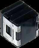
28 General characteristics Caractéristiques générales Applicable for types see below : General purpose : CTS1, CTS13, CTS32, CTS1M Extended ranges : CTS23, CTS23M, CTS33, CTS33M Special for power supplies and converters : CTS21, CTS21E CONSTRUCTION Soldering Soudure Glass metal seal Traversée étanche Soldering Soudure Applicables pour les modèles suivants : Usage général : CTS1, CTS13, CTS32, CTS1M Gammes étendues : CTS23, CTS23M, CTS33, CTS33M Spécial alimentations et convertisseurs : CTS21, CTS21E CONSTRUCTION Metal case métallique Soldering Soudure Nickel lead (positive) Fil nickel (positif) Nickel-Tantalum welding Soudure Nickel-Tantale Tantalum pentoxide Pentoxyde de tantale Tantalum powder Poudre de tantale Manganous dioxide Bioxyde de manganèse Graphite Graphite Argent Silver Nickel lead (négative) Fil nickel (négatif) MARKING MARQUAGE FIRCA CTS + + V µf % Brand/Marquage / Capacitance/Capacité Voltage/Tension Tolerance (except 20%) Tolérance (sauf 20%) Date code = year (année) : 2 digits week (semaine) : 2 digits PACKAGING Depending upon the quantities, there will be different types for packaging : small quantities : loose in plastic bags or boxes intermediate quantities : taped in plastic bags big quantities : taped on reel Dimensions about taping and reels are given on the next page. CONDITIONNEMENT Suivant les quantités, les boîtiers métalliques peuvent être conditionnés sous plusieurs formes : petites quantités : vrac en sachets ou boîtes plastique quantités moyennes : sur bande en sachets plastique grosses quantités : sur bande et bobine Les dimensions concernant la mise en bande et les bobines sont données sur la page suivante. 26
29 Taping : dimensions Mise en bande : dimensions LENGTH OF THE CAPACITOR Longueur du condensateur (+) White ( ) Color ± 1 L* 6 ± 1 K b S TAPE DIMENSIONS (in mm) Dimensions de la bande (mm) Case code L max. K max. * b ± 2 C max. ** S Qty per reel ± 0,5 Nb/bobine Std/max. A 8,1 9, B 12,8 14, C 18,2 18, D 20,8 20, * The size b of 53 mm for B case is the standard dimension. La côte b de 53 mm pour le boîtier B est la dimension standard ** Max. cumulative tolerance on 10 capacitors : ±2 mm Écart max. de tolérance cumulatif sur 10 condensateurs : ±2 mm C REEL SIZE (in mm) Dimensions de la bobine (mm) Ø 16 ± 1 or 27 ± 1 (-) 3 ± 0,5 Ø 81 ± 2 Size E of reels according to case sizes. Côté E des bobines selon les boîtiers. A = 67 B = 67 C-D = 87 Ø 268 ± 2 or 300 ± 2 E 27


30 CTS 1 (SI125) - CTS 13 (SI85) CTS 32 (IS125) - CTS 1M (=CSR13) Solid tantalum capacitors Hermetically sealed metal cases Axial leads Polarized types General purpose - Standard range Condensateurs tantale à électrolyte solide s métalliques hermétiques Sorties axiales Polarisés Gamme standard - Usage général ELECTRICAL AND CLIMATIC CHARACTERISTICS CTS 1 CTS 13 CTS 32 CTS 1M CARACTÉRISTIQUES ÉLECTRIQUES ET CLIMATIQUES Detail speciication CECC CECC CECC MIL-PRF-39003/01 Spéciication particulière CECC CECC Operating temperature 55 C +125 C 55 C 55 C +125 C 55 C +125 C Température d utilisation Damp heat 56 jours / days 56 jours / days 56 jours / days 56 jours / days Chaleur humide Capacitance range 0,1µF µf 0,1µF µf 1µF µf 0,1µF µf Gamme de capacité Tolerance 20%...10% 20%...10% 20%...10% 20%...10% Tolérance Voltage range 6,3V...125V 6,3V...63V 6,3V...63V 6,3V...100V Gamme de tension Max. capacitance change 55 C 10% 10% 10% 10% C / C maximum à 55 C Max. capacitance change +12% +12% +12% +8% C / C maximum à Max. capacitance change +125 C +15% - +15% +12% C / C maximum à +125 C Maximum DF at see table/voir tableau see table/voir tableau see table/voir tableau see table/voir tableau Tg maximum à Maximum DF at 55 C 1,5 x lim20 C 1,5 x lim20 C 1,5 x lim20 C = lim20 C Tg maximum à 55 C Maximum DF at 1,5 x lim20 C 1,5 x lim20 C 1,5 x lim20 C = lim20 C Tg maximum à Maximum DF at +125 C 2,0 x lim20 C 2,0 x lim20 C = lim20 C Tg maximum à +125 C Max. leakage current at see table/voir tableau see table/voir tableau see table/voir tableau see table/voir tableau Courant de fuite max. à Max. leakage current at 0,1 x C R U R 0,1 x C R U R 0,1 x C R U R 20 x lim 20 C Courant de fuite max. à Max. leakage current at +125 C 0,125 x C R U R - 0,125 x C R U R 25 x lim 20 C Courant de fuite max. à +125 C Max. impedance (20 C) : case A 10 Ω 10 Ω 10 Ω 10 Ω Impédance max. (20 C) : boîtier A Max. impedance (20 C) : case B 5 Ω 5 Ω 5 Ω 5 Ω Impédance max. (20 C) : boîtier B Max. impedance (20 C) : case C 2 Ω 2 Ω 2 Ω 2 Ω Impédance max. (20 C) : boîtier C Max. impedance (20 C) : case D 1 Ω 1 Ω 1 Ω 1 Ω Impédance max. (20 C) : boîtier D High surge current non / no non / no 1 million cycles 3 cycles-100% Tenue en charge - décharge Max. reverse voltage at % U R 15 % U R Tension inverse max. à Max. reverse voltage at % U R 5 % U R Tension inverse max. à Max. reverse voltage at +125 C % U R 1 % U R Tension inverse max. à +125 C Max. surge voltage at 1,3 x U R 1,3 x U R 1,3 x U R 1,3 x U R Surtension max. à Max. surge voltage at +125 C 1,3 x U C - 1,3 x U C 1,3 x U C Surtension max. à +125 C DIMENSIONS (mm) Case code Dimensions with insulating sleeve Dimensions avec gaine isolante Lt max L max D max d +10%/ 0,05 A 10,2 8,1 3,6 0,5 B 15,0 12,8 4,9 0,5 C 20,5 18,2 7,5 0,6 D 24,0 20,8 9,1 0,6 MARKING, PACKAGING, CONSTRUCTION : see general characteristics MARQUAGE, CONDITIONNEMENT, CONSTRUCTION : voir caractéristiques générales DIMENSIONS (mm) 30 min (*) L 30 min (*) d Lt (*) 23mm for capacitors delivered on tape D 28
31 CTS 1 - CTS 13 - CTS 32 - CTS 1M STANDARD RATINGS - ELECTRICAL CHARACTERISTICS Capacitance Capacité 100 Hz (µf) Case (code) Max. leakage current Courant de fuite max C Tangente d max. VALEURS STANDARD - CARACTÉRISTIQUES ÉLECTRIQUES Max. leakage current Courant de fuite max. Tangente d max. +25 C Rated voltage / Tension nominale () 6,3 V (6 V for CTS 1M) - Category voltage / Tension de catégorie (+125 C) 4 V 5,6 A CTS1 CTS13 CTS32 1 3,5 4,4 6 CTS1M 0,3 6 7,5 4 6,8 A CTS1 CTS13 CTS32 1 4,2 5,3 6 CTS1M 0,3 6 7, B CTS1 CTS13 CTS32 2, CTS1M 1, B CTS1 CTS13 CTS32 3, CTS1M 1, C CTS32 7, C CTS1 CTS13 CTS32 9, CTS1M 4, C CTS1 CTS13 CTS32 11, CTS1M 5, D CTS1 CTS13 CTS CTS1M 6, D CTS1 CTS13 CTS32 20, CTS1M 7, Rated voltage / Tension nominale () 10 V - Category voltage / Tension de catégorie (+125 C) 6,3 V 3,9 A CTS1 CTS13 CTS32 1 3,9 4,8 6 CTS1M 0,3 6 7,5 4 4,7 A CTS1 CTS13 CTS32 1 4,7 5,8 6 CTS1M 0,4 7 8, B CTS1 CTS13 CTS32 2, CTS1M B CTS1 CTS13 CTS32 3, CTS1M 2, B CTS1 CTS13 CTS32 3, CTS1M 2, C CTS1 CTS13 CTS32 8, CTS1M C CTS1 CTS13 CTS CTS1M C CTS1 CTS CTS1M D CTS1 CTS13 CTS CTS1M D CTS1 CTS13 CTS CTS1M Rated voltage / Tension nominale () 16 V (15 V for CTS 1M) - Category voltage / Tension de catégorie (+125 C) 10 V 1,8 A CTS1 CTS32 1 2,8 3,6 6 2,2 A CTS1 CTS32 1 3,5 4,4 6 2,7 A CTS1 CTS13 CTS32 1 4,3 5,4 6 CTS1M 0,3 6 7,5 4 3,3 A CTS1 CTS13 CTS32 1 5,2 6,6 6 CTS1M 0, B CTS1 CTS32 1, B CTS1 CTS32 2, B CTS1 CTS13 CTS32 2, CTS1M B CTS1 CTS13 CTS32 3, ,7 6 CTS1M C CTS1 CTS32 6, , C CTS1 CTS32 7, , C CTS1 CTS13 CTS32 8, CTS1M C CTS1 CTS13 CTS32 10, CTS1M D CTS1 CTS32 13, D CTS1 CTS D CTS1 CTS13 CTS32 19, CTS1M D CTS1 CTS13 CTS CTS1M Rated voltage / Tension nominale () 20 V - Category voltage / Tension de catégorie (+125 C) 13 V 1,2 A CTS1M 0,3 6 7,5 4 1,5 A CTS1M 0,3 6 7,5 4 1,8 A CTS13 1 3,6 6 CTS1M 0,3 6 7,5 4 2,2 A CTS13 1 4,4 6 CTS1M 0, ,2 B CTS1M B CTS1M 1, B CTS13 2, CTS1M 1, B CTS CTS1M C CTS1M 2, C CTS1M 3, C CTS13 7, CTS1M C CTS13 9, CTS1M 4, D CTS1M 5, D CTS1M D CTS13 16, CTS1M D CTS CTS1M Rated voltage / Tension nominale () 25 V - Category voltage / Tension de catégorie (+125 C) 16 V 1,2 A CTS ,7 6 1,5 A CTS1 CTS13 CTS32 1 3,7 4,6 6 8,2 B CTS1 CTS13 CTS B CTS1 CTS13 CTS32 2, , C +125 C 29
32 CTS 1 - CTS 13 - CTS 32 - CTS 1M STANDARD RATINGS - ELECTRICAL CHARACTERISTICS Capacitance Capacité 100 Hz (µf) Case (code) Max. leakage current Courant de fuite max C Tangente d max. VALEURS STANDARD - CARACTÉRISTIQUES ÉLECTRIQUES Max. leakage current Courant de fuite max. Tangente d max. +25 C Rated voltage / Tension nominale () 25 V - Category voltage / Tension de catégorie (+125 C) 16 V 27 C CTS1 CTS13 CTS32 6, C CTS1 CTS13 CTS32 8, D CTS1 CTS13 CTS D CTS1 CTS13 CTS Rated voltage / Tension nominale () 40 V (35 V for CTS 1M) - Category voltage / Tension de catégorie (+125 C) 25 V (23 V for CTS 1M) 0,1 A CTS1 CTS ,12 A CTS1 CTS ,15 A CTS1 CTS ,18 A CTS1 CTS ,22 A CTS1 CTS ,1 6 0,27 A CTS1 CTS ,3 6 0,33 A CTS1 CTS13 1 1,3 1,6 6 0,39 A CTS1 CTS13 1 1,5 1,9 6 0,47 A CTS1 CTS13 1 1,8 2,3 6 0,56 A CTS1 CTS13 1 2,2 2,8 6 0,68 A CTS1 CTS13 1 2,7 3,4 6 0,82 A CTS1 CTS13 1 3,2 4,1 6 1 A CTS1 CTS13 CTS ,2 A CTS1 CTS13 CTS32 1 4, ,5 B CTS1 CTS13 CTS ,5 6 1,8 B CTS1 CTS13 CTS32 1 7, ,2 B CTS1 CTS13 CTS32 1 8, ,7 B CTS1 CTS13 CTS ,5 6 3,3 B CTS1 CTS13 CTS32 1, ,2 6 3,9 B CTS1 CTS13 CTS32 1, ,7 6 4,7 B CTS1 CTS13 CTS32 1, ,5 6 5,6 B CTS1 CTS13 CTS32 2, ,5 6 CTS1M 1, ,8 B CTS1 CTS13 CTS32 2, ,7 6 CTS1M 1, ,2 C CTS1 CTS13 CTS32 3, C CTS1 CTS13 CTS C CTS1 CTS13 CTS32 4, C CTS1 CTS13 CTS C CTS1 CTS13 CTS32 7, C CTS1 CTS13 CTS32 8, CTS1M D CTS1 CTS13 CTS32 10, CTS1M 4, D CTS1 CTS13 CTS32 13, CTS1M 5, D CTS1 CTS13 CTS32 15, CTS1M D CTS1 CTS13 CTS32 18, CTS1M Rated voltage / Tension nominale () 50 V - Category voltage / Tension de catégorie (+125 C) 32 V 0,1 A CTS1 CTS CTS1M 0,3 5 6,3 2 0,12 A CTS1 CTS CTS1M 0,3 5 6,3 2 0,15 A CTS1 CTS CTS1M 0,3 5 6,3 2 0,18 A CTS1 CTS ,1 6 CTS1M 0,3 5 6,3 2 0,22 A CTS1 CTS13 1 1,1 1,3 6 CTS1M 0,3 5 6,3 2 0,27 A CTS1 CTS13 1 1,3 1,6 6 CTS1M 0,3 5 6,3 2 0,33 A CTS1 CTS13 1 1,6 2 6 CTS1M 0,3 5 6,3 2 0,39 A CTS1 CTS13 1 1,9 2,4 6 CTS1M 0,3 5 6,3 2 0,47 A CTS1 CTS13 1 2,3 2,9 6 CTS1M 0,3 5 6,3 2 0,56 A CTS1 CTS13 1 2,8 3,5 6 CTS1M 0,3 5 6,3 2 0,68 A CTS1 CTS13 1 3,4 4,2 6 CTS1M 0,3 5 6,3 2 0,82 A CTS1 CTS13 1 4,1 5,1 6 CTS1M 0,3 5 6,3 2 1 A CTS1 CTS13 CTS ,2 6 CTS1M 0, ,2 B CTS1 CTS13 CTS ,5 6 CTS1M 0, ,5 B CTS1 CTS13 CTS32 1 7,5 9,3 6 CTS1M 0, ,8 B CTS1 CTS13 CTS ,2 6 CTS1M 0, ,2 B CTS1 CTS13 CTS32 1, ,7 6 CTS1M 0, ,7 B CTS1 CTS13 CTS32 1, ,2 6 CTS1M ,3 B CTS1 CTS13 CTS32 1, CTS1M 1, ,9 B CTS1 CTS13 CTS32 1, CTS1M 1, ,7 B CTS1 CTS13 CTS32 2, CTS1M 1, ,6 C CTS1 CTS13 CTS32 2, CTS1M 2, ,8 C CTS1 CTS13 CTS32 3, CTS1M 2, ,2 C CTS1 CTS13 CTS32 4, CTS1M 2, C CTS1 CTS13 CTS CTS1M 2, C +125 C 30
33 CTS 1 - CTS 13 - CTS 32 - CTS 1M STANDARD RATINGS - ELECTRICAL CHARACTERISTICS Capacitance Capacité 100 Hz (µf) Case (code) Max. leakage current Courant de fuite max C Tangente d max. VALEURS STANDARD - CARACTÉRISTIQUES ÉLECTRIQUES Max. leakage current Courant de fuite max. Tangente d max. +25 C Rated voltage / Tension nominale () 50 V - Category voltage / Tension de catégorie (+125 C) 32 V 12 C CTS1 CTS13 CTS CTS1M C CTS1 CTS13 CTS32 7, CTS1M C CTS1 CTS13 CTS CTS1M 4, D CTS1 CTS13 CTS CTS1M 5, Rated voltage / Tension nominale () 63 V - Category voltage / Tension de catégorie (+125 C) 40 V 0,1 A CTS1 CTS ,12 A CTS1 CTS ,15 A CTS1 CTS ,1 6 0,18 A CTS1 CTS13 1 1,1 1,4 6 0,22 A CTS1 CTS13 1 1,3 1,7 6 0,27 A CTS1 CTS13 1 1,7 2,1 6 0,33 A CTS1 CTS ,5 6 0,39 A CTS1 CTS13 1 2, ,47 A CTS1 CTS13 1 2,9 3,7 6 0,56 A CTS1 CTS13 1 3,5 4,4 6 0,68 A CTS1 CTS13 1 4,2 5,3 6 0,82 B CTS1 CTS13 1 5,1 6,4 6 1 B CTS1 CTS13 CTS32 1 6,3 7,8 6 1,2 B CTS1 CTS13 CTS32 1 7,5 9,4 6 1,5 B CTS1 CTS13 CTS32 1 9,4 11,8 6 1,8 B CTS1 CTS13 CTS32 1, ,7 6 2,2 B CTS1 CTS13 CTS32 1, ,2 6 2,7 B CTS1 CTS13 CTS32 1, ,2 6 3,3 B CTS1 CTS13 CTS ,9 B CTS1 CTS13 CTS32 2, ,7 C CTS1 CTS13 CTS32 2, ,6 C CTS1 CTS13 CTS32 3, ,8 C CTS1 CTS13 CTS32 4, ,2 C CTS1 CTS13 CTS32 5, C CTS1 CTS13 CTS32 6, D CTS1 CTS13 CTS32 7, D CTS1 CTS13 CTS32 9, D CTS1 CTS13 CTS32 11, D CTS1 CTS13 CTS32 13, Rated voltage / Tension nominale () 80 V (75 V for CTS 1M) - Category voltage / Tension de catégorie (+125 C) 50 V 0,1 A CTS CTS1M 0,3 5 6,3 2 0,12 A CTS ,2 6 CTS1M 0,3 5 6,3 2 0,15 A CTS1 1 1,2 1,5 6 CTS1M 0,3 5 6,3 2 0,18 A CTS1 1 1,4 1,8 6 CTS1M 0,3 5 6,3 2 0,22 A CTS1 1 1,7 2,2 6 CTS1M 0,3 5 6,3 2 0,27 A CTS1 1 2,1 2,7 6 CTS1M 0,3 5 6,3 2 0,33 A CTS1 1 2,6 3,3 6 CTS1M 0,3 5 6,3 2 0,39 A CTS1 1 3,1 3,9 6 CTS1M 0,3 5 6,3 2 0,47 A CTS1 1 3,7 4,7 6 CTS1M 0,3 5 6,3 2 0,56 A CTS1 1 4,4 5,6 6 CTS1M 0,3 5 6,3 2 0,68 A CTS1 1 5,4 6,8 6 CTS1M 0,3 5 6,3 2 0,82 B CTS1 1 6,5 8,2 6 CTS1M 0,3 5 6,3 2 1 B CTS CTS1M 0,3 5 6,3 2 1,2 B CTS1 1 9, CTS1M 0,3 5 6,3 4 1,5 B CTS1 1, CTS1M 0, ,8 B CTS1 1, CTS1M 0, ,2 B CTS1 1, CTS1M 0, ,7 B CTS1 2, CTS1M ,3 B CTS1 2, CTS1M 1, ,9 B CTS1 3, CTS1M 1, ,7 C CTS1 3, CTS1M ,6 C CTS1 4, CTS1M ,8 C CTS1 5, CTS1M ,2 C CTS1 6, CTS1M C CTS CTS1M D CTS1 9, CTS1M D CTS CTS1M C +125 C 31
34 CTS 1 - CTS 13 - CTS 32 - CTS 1M STANDARD RATINGS - ELECTRICAL CHARACTERISTICS Capacitance Capacité 100 Hz (µf) Case (code) Max. leakage current Courant de fuite max C Tangente d max. VALEURS STANDARD - CARACTÉRISTIQUES ÉLECTRIQUES Max. leakage current Courant de fuite max. Rated voltage / Tension nominale () 100 V - Category voltage / Tension de catégorie (+125 C) 63 V 0,1 A CTS ,2 6 CTS1M 0,3 5 6,3 2 0,12 A CTS1 1 1,2 1,5 6 CTS1M 0,3 5 6,3 2 0,15 A CTS1 1 1,5 1,8 6 CTS1M 0,3 5 6,3 2 0,18 A CTS1 1 1,8 2,2 6 CTS1M 0,3 5 6,3 2 0,22 A CTS1 1 2,2 2,7 6 CTS1M 0,3 5 6,3 2 0,27 A CTS1 1 2,7 3,3 6 CTS1M 0,3 5 6,3 2 0,33 A CTS1 1 3,3 4,1 6 CTS1M 0,3 5 6,3 2 0,39 A CTS1 1 3,9 4,8 6 CTS1M 0,3 5 6,3 2 0,47 A CTS1 1 4,7 5,8 6 CTS1M 0,3 5 6,3 2 0,56 A CTS1 1 5,6 7 6 CTS1M 0,3 5 6,3 2 0,68 B CTS1 1 6,8 8,5 6 CTS1M 0,3 5 6,3 2 0,82 B CTS1 1 8, CTS1M 0,4 5 6,3 2 1 B CTS CTS1M 0,5 5 6,3 2 1,2 B CTS1 1, CTS1M 0,5 5 6,3 4 1,5 B CTS1 1, CTS1M 0, ,8 B CTS1 1, CTS1M 0, ,2 B CTS1 2, CTS1M 0, ,7 B CTS1 2, CTS1M 1, ,3 C CTS1 3, CTS1M 1, ,9 C CTS1 3, CTS1M 1, ,7 C CTS1 4, CTS1M 2, ,6 C CTS1 5, CTS1M 2, ,8 C CTS1 6, CTS1M 2, ,2 D CTS1 8, D CTS Rated voltage / Tension nominale () 125 V - Category voltage / Tension de catégorie (+125 C) 80 V 0,1 A CTS1 1 1,2 1,5 6 0,12 A CTS1 1 1,5 1,8 6 0,15 A CTS1 1 1,8 2,3 6 0,18 A CTS1 1 2,2 2,8 6 0,22 A CTS1 1 2,7 3,4 6 0,27 A CTS1 1 3,3 4,2 6 0,33 A CTS1 1 4,1 5,1 6 0,39 B CTS1 1 4, ,47 B CTS1 1 5,8 7,3 6 0,56 B CTS ,7 6 0,68 B CTS1 1 8, ,82 B CTS B CTS1 1, ,2 B CTS1 1, ,5 B CTS1 1, ,8 B CTS1 2, ,2 B CTS1 2, ,7 C CTS1 3, ,3 C CTS1 4, ,9 C CTS1 4, ,7 C CTS1 5, ,6 C CTS ,8 C CTS1 8, ,2 D CTS1 10, D CTS1 12, C +125 C Tangente d max. +25 C 32

35 CTS 23 (SIS125) - CTS 23M (=CSR23) CTS 33 (SISFR125) - CTS 33M (=CSR33) Solid tantalum capacitors Hermetically sealed metal cases Axial leads Polarized types General purpose - Extended range Condensateurs tantale à électrolyte solide s métalliques hermétiques Sorties axiales Polarisés Gamme étendue - Usage général ELECTRICAL AND CLIMATIC CHARACTERISTICS CTS 23 CTS 23M CTS 33 CTS 33M CARACTÉRISTIQUES ÉLECTRIQUES ET CLIMATIQUES Detail speciication CECC MIL PRF 39003/03 CECC MIL-PRF-39003/06 Spéciication particulière Operating temperature 55 C +125 C 55 C +125 C 55 C +125 C 55 C +125 C Température d utilisation Damp heat 56 days/jours 56 jours / days 56 days/jours 56 days/jours Chaleur humide Capacitance range 1µF µf 1,2µF µf 1,2µF µf 1,2µF µf Gamme de capacité Tolerance 20%...10% 20%...10% 20%...10% 20%...10% Tolérance Voltage range 6,3V...63V 6,3V...50V 6,3V...50V 6,3V...50V Gamme de tension Max. capacitance change 55 C 10% 10% 10% 10% C / C maximum à 55 C Max. capacitance change +12% +8% +8% +8% C / C maximum à Max. capacitance change +125 C +15% +12% +12% +12% C / C maximum à +125 C Maximum DF at see table/voir tableau see table/voir tableau see table/voir tableau see table/voir tableau Tg maximum à Maximum DF at 55 C = lim20 C 1,5 x lim20 C = lim20 C = lim20 C Tg maximum à 55 C Maximum DF at = lim20 C 1,5 x lim20 C = lim20 C = lim20 C Tg maximum à Maximum DF at +125 C = lim20 C = lim20 C = lim20 C Tg maximum à +125 C Max. leakage current at see table/voir tableau see table/voir tableau see table/voir tableau see table/voir tableau Courant de fuite max. à Max. leakage current at 0,1 x C R U R 10 x lim 20 C 0,1 x C R U R Courant de fuite max. à Max. leakage current at +125 C 0,125 x C R U R 12,5 x lim 20 C 0,125 x C R U R Courant de fuite max. à +125 C Max. impedance (20 C) : case A 10 Ω 10 Ω 10 Ω 10 Ω Impédance max. (20 C) : boîtier A Max. impedance (20 C) : case B 5 Ω 5 Ω 5 Ω 5 Ω Impédance max. (20 C) : boîtier B Max. impedance (20 C) : case C 2 Ω 2 Ω 2 Ω 2 Ω Impédance max. (20 C) : boîtier C Max. impedance (20 C) : case D 1 Ω 1 Ω 1 Ω 1 Ω Impédance max. (20 C) : boîtier D High surge current 1 million cycles 3 cycles-100% 1 million cycles 3 cycles-100% Tenue en charge - décharge Max. reverse voltage at 15 % U R 15 % U R 15 % U R 15 % U R Tension inverse max. à Max. reverse voltage at 5 % U R 5 % U R 5 % U R 5 % U R Tension inverse max. à Max. reverse voltage at +125 C 1 % U R 1 % U R 1 % U R 1 % U R Tension inverse max. à +125 C Max. surge voltage at 1,3 x U R 1,3 x U R 1,3 x U R 1,3 x U R Surtension max. à Max. surge voltage at +125 C 1,3 x U C 1,3 x U C 1,3 x U C 1,3 x U C Surtension max. à +125 C DIMENSIONS (mm) Case code Dimensions with insulating sleeve Dimensions avec gaine isolante Lt max L max D max d +10%/ 0,05 A 10,2 8,1 3,6 0,5 B 15,0 12,8 4,9 0,5 C 20,5 18,2 7,5 0,6 D 24,0 20,8 9,1 0,6 MARKING, PACKAGING, CONSTRUCTION : see general characteristics MARQUAGE, CONDITIONNEMENT, CONSTRUCTION : voir caractéristiques générales DIMENSIONS (mm) 30 min (*) L 30 min (*) d D Lt (*) 23mm for capacitors delivered on tape 33
36 CTS 23 - CTS 23M - CTS 33 - CTS 33M STANDARD RATINGS - ELECTRICAL CHARACTERISTICS VALEURS STANDARD - CARACTÉRISTIQUES ÉLECTRIQUES Capacitance Capacité 100 Hz (µf) Case (code) Max. I leak I fuite max. Tang. d max. Max. I leak I fuite max. +25 C Tang. d max. +25 C Max. I leak I fuite max. Tang. d max. Max. I leak I fuite max. +25 C Rated voltage / Tension nominale () 6,3 V - Category voltage / Tension de catégorie (+125 C) 4 V 10 A CTS23M 0,9 6 CTS33M 0, A CTS CTS23M 1 6 CTS CTS33M 0, A CTS CTS B CTS23 6,3 8 CTS23M 6 8 CTS CTS33M B CTS23 7,5 8 CTS C CTS23 20,8 10 CTS23M 15 8 CTS CTS33M C CTS23 24,5 10 CTS23M CTS33 2,4 10 CTS33M C CTS23 29,6 10 CTS23M CTS33 2,9 10 CTS33M D CTS23 42,8 10 CTS23M CTS33 4,2 10 CTS33M D CTS23 51,6 10 CTS23M CTS33 5,1 10 CTS33M D CTS23 63,0 10 CTS23M CTS33 6,3 10 CTS33M * D CTS23 75,6 10 Rated voltage / Tension nominale () 10 V - Category voltage / Tension de catégorie (+125 C) 6,3 V 6,8 A CTS23M 1 6 CTS33M 0,5 6 8,2 A CTS CTS23M 1,2 6 CTS CTS33M 0, A CTS CTS B CTS23 4,7 6 CTS23M 5 6 CTS CTS33M B CTS23 5,6 6 CTS23M 6 6 CTS CTS33M B CTS23 6,8 8 CTS23M 7 6 CTS CTS33M B CTS23 8,2 8 CTS23M 8 6 CTS CTS33M C CTS CTS23M 15 8 CTS33 2,2 10 CTS33M C CTS CTS23M 15 8 CTS33 2,7 10 CTS33M D CTS CTS23M CTS33 3,9 10 CTS33M D CTS CTS23M CTS33 4,7 10 CTS33M D CTS CTS23M CTS33 5,6 10 CTS33M 4 10 Rated voltage / Tension nominale () 16 V - Category voltage / Tension de catégorie (+125 C) 10 V 4,7 A CTS23M 1 4 CTS33M 0,5 4 5,6 A CTS CTS23M 1,3 4 CTS CTS33M 0,5 4 6,8 A CTS CTS B CTS23 5,2 6 CTS23M 6 6 CTS CTS33M B CTS23 6,2 8 CTS23M 6 6 CTS CTS33M C CTS CTS23M 15 8 CTS33 2,4 10 CTS33M C CTS23 28,8 10 CTS23M 15 8 CTS33 2,8 10 CTS33M D CTS23M 20 8 CTS33M D CTS23 43,2 10 CTS23M 20 8 CTS33 4,3 10 CTS33M D CTS23 52,8 10 CTS23M 20 8 CTS33 5,2 10 CTS33M 2 8 Rated voltage / Tension nominale () 20 V - Category voltage / Tension de catégorie (+125 C) 13 V 2,7 A CTS23M 0,8 4 CTS33M 0,5 4 3,3 A CTS23M 1 4 CTS33M 0,5 4 3,9 A CTS CTS23M 1,2 4 CTS CTS33M 0,5 4 4,7 A CTS CTS B CTS23M 4 6 CTS33M B CTS23M 4 6 CTS33M B CTS23 5,4 6 CTS23M 5 6 CTS CTS33M C CTS23M 9 6 CTS33M C CTS23M 10 6 CTS33M C CTS23M 10 6 CTS33M C CTS CTS23M 15 6 CTS CTS33M C CTS CTS23M 15 6 CTS33 2,4 10 CTS33M D CTS23M 20 8 CTS33M D CTS CTS23M 20 8 CTS33 3,6 10 CTS33M D CTS CTS33 4,4 10 Rated voltage / Tension nominale () 25 V - Category voltage / Tension de catégorie (+125 C) 16 V 2,2 A CTS CTS ,7 A CTS CTS ,3 A CTS CTS B CTS CTS B CTS23 3,7 6 CTS B CTS23 4,5 6 CTS B CTS23 5,5 6 CTS Tang. d max. +25 C * out of CECC range * hors gamme CECC 34
37 CTS 23 - CTS 23M - CTS 33 - CTS 33M STANDARD RATINGS - ELECTRICAL CHARACTERISTICS VALEURS STANDARD - CARACTÉRISTIQUES ÉLECTRIQUES Capacitance Capacité 100 Hz (µf) Case (code) Max. I leak I fuite max. Tang. d max. Max. I leak I fuite max. +25 C Tang. d max. +25 C Max. I leak I fuite max. Tang. d max. Max. I leak I fuite max. +25 C Rated voltage / Tension nominale () 25 V - Category voltage / Tension de catégorie (+125 C) 16 V 56 C CTS CTS33 1, C CTS CTS33 1, C CTS23 20,5 10 CTS * D CTS CTS33 2, D CTS CTS D CTS23 37,5 10 CTS33 3,7 10 Rated voltage / Tension nominale () 40 V (35 V for CTS 23M - CTS 33M) - Category voltage / Tension de catégorie (+125 C) 16 V (23 V for CTS 23M - CTS 33M) 1,2 A CTS ,5 A CTS CTS ,8 A CTS CTS23M 1 4 CTS CTS33M 0,5 4 8,2 B CTS23 3,2 6 CTS23M 3,5 6 CTS CTS33M B CTS CTS23M 4 6 CTS CTS33M C CTS23 10,8 8 CTS C CTS23 13,2 8 CTS23M 10 6 CTS33 1,3 8 CTS33M C CTS23 15,6 8 CTS23M 10 6 CTS33 1,5 8 CTS33M C CTS23 18,8 8 CTS23M 10 6 CTS33 1,8 8 CTS33M D CTS23 22,4 10 CTS23M 15 6 CTS33 2,2 10 CTS33M D CTS23 27,2 10 CTS23M 15 6 CTS33 2,7 10 CTS33M D CTS23 32,8 10 CTS33 3, D CTS CTS * D CTS Rated voltage / Tension nominale () 50 V - Category voltage / Tension de catégorie (+125 C) 32 V 1,2 A CTS CTS23M 0,9 4 CTS CTS33M 0,5 4 1,5 A CTS CTS23M 1,2 4 CTS CTS33M 0,5 4 5,6 B CTS23 2,8 6 CTS23M 4,5 4 CTS CTS33M 1 4 6,8 B CTS23 3,4 6 CTS23M 4,5 6 CTS CTS33M C CTS CTS23M 10 6 CTS33 1,1 8 CTS33M C CTS23 13,5 8 CTS23M 10 6 CTS33 1,3 8 CTS33M D CTS23 16,5 8 CTS23M 10 6 CTS33 1,6 8 CTS33M D CTS23 19,5 8 CTS23M 10 6 CTS33 1,9 8 CTS33M * D CTS23 23, * D CTS * D CTS Rated voltage / Tension nominale () 63 V - Category voltage / Tension de catégorie (+125 C) 40 V 1* A CTS ,7* B CTS23 2,9 6 5,6* B CTS23 3,5 6 15* C CTS23 9,4 8 18* C CTS23 11,3 8 22* C CTS23 13,8 8 27* D CTS * D CTS23 20, * D CTS23 24, * D CTS23 29,6 10 Tang. d max. +25 C * out of CECC range * hors gamme CECC 35

38 CTS 21 (SIZR125) - CTS 21M (=CSR21) CTS 21E (SIZR125) ESCC 3002/003 Solid tantalum capacitors Hermetically sealed metal cases Axial leads Polarized types For power supplies and converters Condensateurs tantale à électrolyte solide s métalliques hermétiques Sorties axiales Polarisés Pour alimentation et convertisseurs ELECTRICAL AND CLIMATIC CHARACTERISTICS CTS 21 CTS 21M CTS 21E CARACTÉRISTIQUES ÉLECTRIQUES ET CLIMATIQUES Detail speciication CECC MIL-PRF-39003/09 CECC Spéciication particulière ESCC 3002/003 Operating temperature 55 C +125 C 55 C +125 C 55 C +125 C Température d utilisation Damp heat 56 days/jours 56 days/jours 56 days/jours Chaleur humide Capacitance range 5,6µF µf 5,6µF µf 22µF µf Gamme de capacité Tolerance 20%...10% 20%...10% 20%...10% Tolérance Voltage range 6,3V...50V 6,3V...50V 6,3V...50V Gamme de tension Max. capacitance change 55 C 10% 10% 10% C / C maximum à 55 C Max. capacitance change +8% +8% +8% C / C maximum à Max. capacitance change +125 C +12% +12% +12% C / C maximum à +125 C Maximum DF at see table/voir tableau see table/voir tableau see table/voir tableau Tg maximum à Maximum DF at 55 C = 2 x lim20 C = 2 x lim20 C = 2 x lim20 C Tg maximum à 55 C Maximum DF at = 1,5 x lim20 C = 1,5 x lim20 C = 1,5 x lim20 C Tg maximum à Maximum DF at +125 C = 1,5 x lim20 C = 1,5 x lim20 C = 1,5 x lim20 C Tg maximum à +125 C Max. leakage current at see table/voir tableau see table/voir tableau see table/voir tableau Courant de fuite max. à Max. leakage current at 0,1 x C R U R 20 x lim 20 C 0,1 x C R U R Courant de fuite max. à Max. leakage current at +125 C 0,125 x C R U R 25 x lim 20 C 0,125 x C R U R Courant de fuite max. à +125 C Max. ESR at 100 khz see table/voir tableau see table/voir tableau see table/voir tableau RSE maximum (100 khz) à Max. ripple current 1kHz see table/voir tableau see table/voir tableau see table/voir tableau Courant eficace max. à 1kHz Max. ripple current 100 khz see table/voir tableau see table/voir tableau see table/voir tableau Courant eficace max. à 100 khz High surge current 1 million cycles 3 cycles-100% 1 million cycles Tenue en charge - décharge Max. reverse voltage at 15 % U R 15 % U R 15 % U R Tension inverse max. à Max. reverse voltage at 5 % U R 5 % U R 5 % U R Tension inverse max. à Max. reverse voltage at +125 C 1 % U R 1 % U R 1 % U R Tension inverse max. à +125 C Max. surge voltage at 1,3 x U R 1,3 x U R 1,3 x U R Surtension max. à Max. surge voltage at +125 C 1,3 x U C 1,3 x U C 1,3 x U C Surtension max. à +125 C DIMENSIONS (mm) Case code Dimensions with insulating sleeve Dimensions avec gaine isolante Lt max L max D max d +10%/ 0,05 C 20,5 18,2 7,5 0,6 D 24,0 20,8 9,1 0,6 DIMENSIONS (mm) 30 min (*) L 30 min (*) d D MARKING, PACKAGING, CONSTRUCTION : see general characteristics MARQUAGE, CONDITIONNEMENT, CONSTRUCTION : voir caractéristiques générales Lt (*) 23mm for capacitors delivered on tape 36
39 CTS 21 - CTS 21M STANDARD RATINGS - ELECTRICAL CHARACTERISTICS Capacitance Capacité 1kHz (µf) Case (code) Max. I leak I fuite max. Tang. d max. 1kHz Max. ESR RSE max. 100 khz (mω) Irms Max. Ieff. max. 1 khz (A) Irms Max. Ieff. max. 100 khz (A) VALEURS STANDARD - CARACTÉRISTIQUES ÉLECTRIQUES Max. I leak I fuite max. +25 C Tang. d max. 1kHz +25 C Max. ESR RSE max. 100 khz +25 C (mω) Irms Max. Ieff. max. 1 khz +25 C (A) Rated voltage / Tension nominale () 6,3 V (6 V for CTS 21M) - Category voltage / Tension de catégorie (+125 C) 4 V 120 C CTS21 7, ,5 3,2 150 C CTS21 9, ,3 CTS21M 4, ,3 180 C CTS21M 5, ,4 3,4 270 D CTS ,4 4,1 CTS21M 6, ,4 4,1 330 D CTS21 20, ,8 4,3 CTS21M 7, ,8 4,3 Rated voltage / Tension nominale () 10 V - Category voltage / Tension de catégorie (+125 C) 6,3 V 82 C CTS21 8, ,8 2,9 CTS21M ,8 2,9 100 C CTS ,2 3 CTS21M , C CTS21M ,5 3,2 180 D CTS ,4 3,7 CTS21M ,4 3,7 220 D CTS ,4 3,9 CTS21M ,4 3,9 Rated voltage / Tension nominale () 16 V (15 V for CTS 21M) - Category voltage / Tension de catégorie (+125 C) 10 V 56 C CTS21 8, ,8 2,6 CTS21M ,8 2,6 68 C CTS21 10, ,2 2,7 CTS21M ,2 2,7 120 D CTS21 19, ,8 3,5 CTS21M ,8 3,5 150 D CTS ,1 3,6 CTS21M ,1 3,6 Rated voltage / Tension nominale () 20 V - Category voltage / Tension de catégorie (+125 C) 13 V 27 C CTS21M 2, ,2 2,2 33 C CTS21M 3, ,4 2,3 39 C CTS21 7, ,7 2,4 CTS21M ,7 2,4 47 C CTS21 9, ,8 2,5 CTS21M 4, ,8 2,5 56 D CTS21M 5, ,2 2,9 68 D CTS21M , D CTS21 16, ,5 3,1 CTS21M ,5 3,1 100 D CTS ,5 3,3 CTS21M ,5 3,3 Rated voltage / Tension nominale () 25 V - Category voltage / Tension de catégorie (+125 C) 16 V 27 C CTS21 6, ,2 2,2 33 C CTS21 8, ,4 2,3 56 D CTS ,2 2,9 68 D CTS ,4 3 Rated voltage / Tension nominale () 35 or 40 V (35 V for CTS 21M) - Category voltage / Tension de catégorie (+125 C) 23 or 25 V 22 C CTS21 7, ,5 2,1 CTS21M ,5 2,1 27 D CTS21 9, ,9 2,4 CTS21M 4, ,9 2,4 33 D CTS21 11, ,9 2,5 CTS21M 5, ,9 2,5 39 D CTS21 13, ,6 CTS21M ,6 47 D CTS21 16, ,2 2,7 CTS21M ,2 2,7 Rated voltage / Tension nominale () 50 V - Category voltage / Tension de catégorie (+125 C) 32 V 5,6 C CTS21 2, ,6 1,5 CTS21M 2, ,6 1,5 6,8 C CTS21 3, ,7 1,6 CTS21M 2, ,7 1,6 8,2 C CTS21 4, ,9 1,6 CTS21M 2, ,9 1,6 10 C CTS ,1 1,7 CTS21M 2, ,1 1,7 12 C CTS ,3 1,8 CTS21M ,3 1,8 15 C CTS21 7, ,4 1,9 CTS21M ,4 1,9 18 C CTS ,4 2,0 CTS21M 4, ,4 2,0 22 D CTS ,7 2,3 CTS21M 5, ,7 2,3 Irms Max. Ieff. max. 100 khz +25 C (A) 37
40 CTS 21E STANDARD RATINGS - ELECTRICAL CHARACTERISTICS Capacitance Capacité 1kHz (µf) Case (code) Max. I leak I fuite max. Tang. d max. 1kHz VALEURS STANDARD - CARACTÉRISTIQUES ÉLECTRIQUES Max. ESR RSE max. 100 khz (mω) Irms Max. Ieff. max. 1 khz (A) Rated voltage / Tension nominale () 6,3 V - Category voltage / Tension de catégorie (+125 C) 4 V 330 C CTS21E 20, ,4 3,9 390 C CTS21E 24, ,6 4,1 470 C CTS21E 29, ,6 4,2 680 D CTS21E 42, ,0 5,2 820 D CTS21E 51, ,0 5, D CTS21E ,1 5,7 Rated voltage / Tension nominale () 10 V - Category voltage / Tension de catégorie (+125 C) 6,3 V 220 C CTS21E ,2 3,6 270 C CTS21E ,4 3,7 390 D CTS21E ,8 4,5 470 D CTS21E ,8 4,5 560 D CTS21E ,9 4,8 Rated voltage / Tension nominale () 16 V - Category voltage / Tension de catégorie (+125 C) 10 V 150 C CTS21E ,0 3,3 180 C CTS21E 28, ,4 3,4 270 D CTS21E 43, ,4 4,1 330 D CTS21E 52, ,8 4,3 Rated voltage / Tension nominale () 20 V - Category voltage / Tension de catégorie (+125 C) 13 V 100 C CTS21E ,2 3,0 120 C CTS21E ,5 3,2 180 D CTS21E ,4 3,7 220 D CTS21E ,4 3,9 Rated voltage / Tension nominale () 25 V - Category voltage / Tension de catégorie (+125 C) 16 V 56 C CTS21E ,8 2,6 68 C CTS21E ,2 2,7 82 C CTS21E 20, ,2 2,9 150 D CTS21E 37, ,8 3,6 Rated voltage / Tension nominale () 35 or 40 V - Category voltage / Tension de catégorie (+125 C) 23 or 25 V 33 C CTS21E 11, ,4 2,3 39 C CTS21E 13, ,7 2,4 47 C CTS21E 16, ,8 2,5 56 D CTS21E 19, ,2 2,9 68 D CTS21E 23, ,4 3,0 82 D CTS21E 28, ,5 3,1 100 D CTS21E ,5 3,3 120 D CTS21E ,8 3,5 Rated voltage / Tension nominale () 50 V - Category voltage / Tension de catégorie (+125 C) 32 V 22 C CTS21E ,5 2,1 27 C CTS21E 13, ,5 2,2 33 D CTS21E 16, ,9 2,5 39 D CTS21E 19, ,0 2,6 47 D CTS21E 23, ,2 2,7 56 D CTS21E ,2 2,9 68 D CTS21E ,4 3,0 Rated voltage / Tension nominale () 63 V - Category voltage / Tension de catégorie (+125 C) 40 V 47* D CTS21E 29, ,2 2,7 Irms Max. Ieff. max. 100 khz (A) * out of CECC range * hors gamme CECC 38

41 CTS 20 (NSI125) CTS 20E (NSIS125) Solid tantalum capacitors Hermetically sealed metal cases Axial leads Non Polarized types Condensateurs tantale à électrolyte solide s métalliques hermétiques Sorties axiales Non polarisés ELECTRICAL AND CLIMATIC CHARACTERISTICS CARACTÉRISTIQUES ÉLECTRIQUES ET CLIMATIQUES CTS 20 CTS 20E Detail speciication CECC Spéciication particulière Operating temperature 55 C +125 C 55 C +125 C Température d utilisation Damp heat 56 jours / days 56 jours / days Chaleur humide Capacitance range 0,22µF µf 0,47µF µf Gamme de capacité Tolerance 20%...10% 20%...10% Tolérance Voltage range 6,3V...63V 6,3V...63V Gamme de tension Max. capacitance change 55 C 10% 10% C / C maximum à 55 C Max. capacitance change +12% +12% C / C maximum à Max. capacitance change +125 C +15% +15% C / C maximum à +125 C Maximum DF at see table/voir tableau see table/voir tableau Tg maximum à Maximum DF at 55 C see table/voir tableau see table/voir tableau Tg maximum à 55 C Maximum DF at see table/voir tableau see table/voir tableau Tg maximum à Maximum DF at +125 C see table/voir tableau see table/voir tableau Tg maximum à +125 C Max. leakage current at see table/voir tableau see table/voir tableau Courant de fuite max. à Max. leakage current at see table/voir tableau see table/voir tableau Courant de fuite max. à Max. leakage current at +125 C see table/voir tableau see table/voir tableau Courant de fuite max. à +125 C Max. impedance (20 C) : case A see table/voir tableau see table/voir tableau Impédance max. (20 C) : boîtier A Max. impedance (20 C) : case B see table/voir tableau see table/voir tableau Impédance max. (20 C) : boîtier B Max. impedance (20 C) : case C see table/voir tableau see table/voir tableau Impédance max. (20 C) : boîtier C Max. impedance (20 C) : case D see table/voir tableau see table/voir tableau Impédance max. (20 C) : boîtier D High surge current non / no non / no Tenue en charge - décharge Max. reverse voltage at U R U R Tension inverse max. à Max. reverse voltage at U R U R Tension inverse max. à Max. reverse voltage at +125 C U C U C Tension inverse max. à +125 C Max. surge voltage at 1,15 x U R 1,15 x U R Surtension max. à Max. surge voltage at +125 C 1,15 x U C 1,15 x U C Surtension max. à +125 C DIMENSIONS (mm) Case code Dimensions with insulating sleeve Dimensions avec gaine isolante DIMENSIONS (mm) L Lt max L max D max d +10%/ 0,05 A 19,1 15,5 4,5 0,5 B ,6 0,5 C ,4 0,6 D ,6 d FIRCA CTS20 + µf V% + Lt D MARKING, PACKAGING, CONSTRUCTION : see general characteristics MARQUAGE, CONDITIONNEMENT, CONSTRUCTION : voir caractéristiques générales Note : the older case size B2 is no more on the table of standard ratings but can be manufactured for replacement use. Note : l ancien boîtier B2 n apparaît plus sur la grille des valeurs mais est toujours fabriqué pour la maintenance. 39
42 CTS 20 STANDARD RATINGS - ELECTRICAL CHARACTERISTICS Capacitance Capacité 100 Hz (µf) Case (code) Max. leakage current Courant de fuite max C VALEURS STANDARD - CARACTÉRISTIQUES ÉLECTRIQUES Tangente d max. Max. Impedance Impédance max. (Ω) Rated voltage / Tension nominale () 6,3 V - Category voltage / Tension de catégorie (+125 C) 4 V 3,3 A CTS20 2 4,1 5, B CTS20 2, , C CTS20 8, D CTS20 18, Rated voltage / Tension nominale () 10 V - Category voltage / Tension de catégorie (+125 C) 6,3 V 2,2 A CTS20 2 4,4 5, B CTS , C CTS20 9, D CTS Rated voltage / Tension nominale () 16 V - Category voltage / Tension de catégorie (+125 C) 10 V 1,5 A CTS20 2 4, B CTS20 3, C CTS20 10, D CTS20 21, Rated voltage / Tension nominale () 20 V - Category voltage / Tension de catégorie (+125 C) 13 V 1 A CTS ,8 B CTS20 2, C CTS20 8, D CTS20 18, Rated voltage / Tension nominale () 25 V - Category voltage / Tension de catégorie (+125 C) 16 V 0,68 A CTS20 2 3,4 4, ,7 B CTS20 2, , C CTS20 7, , D CTS20 16, Rated voltage / Tension nominale () 40 V - Category voltage / Tension de catégorie (+125 C) 25 V 0,22 A CTS , ,33 A CTS20 2 2,6 3, ,47 A CTS20 2 3,7 4, ,68 B CTS20 2 5,4 6, B CTS ,5 B CTS ,2 B CTS , ,3 B CTS20 2, ,7 C CTS20 3, ,8 C CTS20 5, C CTS D CTS D CTS20 17, Rated voltage / Tension nominale () 50 V - Category voltage / Tension de catégorie (+125 C) 32 V 0,22 A CTS20 2 2,2 2, ,33 A CTS20 2 3,3 4, ,47 A CTS20 2 4,7 5, ,68 B CTS20 2 6,8 8, B CTS , ,5 B CTS , ,2 B CTS20 2, , ,3 C CTS20 3, , ,7 C CTS20 4, , ,8 C CTS20 6, D CTS Rated voltage / Tension nominale () 63 V - Category voltage / Tension de catégorie (+125 C) 40 V 0,22 A CTS20 2 2,7 3, ,33 A CTS20 2 4,1 5, ,47 B CTS20 2 5,9 7, ,68 B CTS20 2 8,5 10, B CTS ,6 15, ,5 B CTS ,9 23, ,8 B CTS20 2, , ,2 C CTS20 2, , ,3 C CTS20 4, , ,7 C CTS20 5, ,8 D CTS20 8, D CTS20 12, C +125 C 40
43 CTS 20E STANDARD RATINGS - ELECTRICAL CHARACTERISTICS Capacitance Capacité 100 Hz (µf) Case (code) Max. leakage current Courant de fuite max C VALEURS STANDARD - CARACTÉRISTIQUES ÉLECTRIQUES Tangente d max. Max. Impedance Impédance max. (Ω) Rated voltage / Tension nominale () 6,3 V - Category voltage / Tension de catégorie (+125 C) 4 V 5,6 A CTS20E 2 7 8, ,8 A CTS20E 2 8,5 10, B CTS20E 5, B CTS20E , C CTS20E 18, C CTS20E 22, C CTS20E 27, D CTS20E D CTS20E 41, D CTS20E 49, D CTS20E 59, D CTS20E 70, Rated voltage / Tension nominale () 10 V - Category voltage / Tension de catégorie (+125 C) 6,3 V 3,9 A CTS20E 2 7,8 9, ,7 A CTS20E 2 9,4 11, B CTS20E 4, B CTS20E 5, , B CTS20E 6, , B CTS20E 7, , C CTS20E C CTS20E D CTS20E D CTS20E Rated voltage / Tension nominale () 16 V - Category voltage / Tension de catégorie (+125 C) 10 V 2,7 A CTS20E 2 8,6 10, ,3 A CTS20E 2 10,5 13, B CTS20E 4, B CTS20E 5, C CTS20E 17, C CTS20E 21, C CTS20E 26, D CTS20E 38, D CTS20E Rated voltage / Tension nominale () 20 V - Category voltage / Tension de catégorie (+125 C) 13 V 1,8 A CTS20E 2 7, ,2 A CTS20E 2 8, B CTS20E 4, C CTS20E 18, C CTS20E 22, D CTS20E 32, D CTS20E Rated voltage / Tension nominale () 25 V - Category voltage / Tension de catégorie (+125 C) 16 V 1 A CTS20E 2 5 6, ,5 A CTS20E 2 7,5 9, ,6 B CTS20E 2, ,8 B CTS20E 3, , ,2 B CTS20E 4, , B CTS20E , C CTS20E 13, C CTS20E 16, C CTS20E 19, D CTS20E C +125 C 41
44 CTS 20E STANDARD RATINGS - ELECTRICAL CHARACTERISTICS Capacitance Capacité 100 Hz (µf) Case (code) Max. leakage current Courant de fuite max C VALEURS STANDARD - CARACTÉRISTIQUES ÉLECTRIQUES Tangente d max. Max. Impedance Impédance max. (Ω) Rated voltage / Tension nominale () 40 V - Category voltage / Tension de catégorie (+125 C) 25 V 0,56 A CTS20E 2 4,4 5, ,68 A CTS20E 2 5,4 6, ,82 A CTS20E 2 6,5 8, ,9 B CTS20E 3, ,7 B CTS20E 3, C CTS20E 9, C CTS20E C CTS20E 14, C CTS20E 17, D CTS20E 21, D CTS20E 26, D CTS20E 31, D CTS20E 37, D CTS20E 44, Rated voltage / Tension nominale () 50 V - Category voltage / Tension de catégorie (+125 C) 32 V 0,56 A CTS20E 2 5, ,68 A CTS20E 2 6,8 8, ,7 B CTS20E 2, , ,3 B CTS20E 3, , C CTS20E C CTS20E D CTS20E D CTS20E D CTS20E D CTS20E D CTS20E Rated voltage / Tension nominale () 63 V - Category voltage / Tension de catégorie (+125 C) 40 V 0,47 A CTS20E 2 5,9 7, ,2 B CTS20E , ,7 B CTS20E 3, , ,6 C CTS20E , ,8 C CTS20E 8, ,2 C CTS20E 10, C CTS20E 12, D CTS20E 18, D CTS20E 22, D CTS20E 27, C +125 C 42
45 General characteristics Caractéristiques générales Applicable for types see below : General purpose : CTS 4-44, SBM 125, CTS 41, CTS 27, CTS26 Special for power supplies and converters : CTS 41RSE CONSTRUCTION Applicables pour les modèles suivants : Usage général : CTS 4-44, SBM 125, CTS 41, CTS 27, CTS26 Special alimentations et convertisseurs : CTS 41RSE CONSTRUCTION Tantalum powder Poudre de tantale Tantalum pentoxide Pentoxyde de tantale Manganous dioxide Bioxyde de manganèse Graphite Graphite Argent Silver Nickel lead (positive) Fil nickel (positif) Soldering Soudure Epoxy resin Résine époxy Tantalum wire Fil de tantale Nickel lead (negative) Fil de nickel (négatif) MARKING MARQUAGE Capacitance/Capacité (µf) Tolérance (sauf 20%) 10% = K or silver dot K ou point argent 5% = J or gold dot J ou point or Voltage/Tension (V) White dot for CTS41 RSE Point blanc pour CTS41 RSE Polarity mark : red dot Repère polarité : point rouge 100 µ + CTS 27 F Date code year/année : 2 digits week/semaine : 2 digits CTS 27 Tolerance 10% : silver/argent 5% : gold/or Capa tance/capacité (µf) Multiplier/Multiplicateur 2nd digit/2ème chiffre 1rst digit/1er chiffre (see colour codes ) (voir code couleurs) Case sizes B, C and D s B, C et D Case size A A Coded marking Marquage en code Direct marking Marquage en clair COLOR CODE Color Couleur Digit Chiffre Multiplier Multiplicateur Color Couleur Digit Chiffre CODE COULEURS Multiplier Multiplicateur Black / Noir 0 Green /Vert 5 10 Brown /Marron 1 Blue /Bleu 6 x 1 Red /Rouge 2 Violet /Violet 7 x 10 Orange /Orange 3 Grey /Gris 8 Yellow /Jaune White /Blanc 9 PACKAGING CONDITIONNEMENT CTS27 : case sizes A and B : on tape (see next page) case sizes C and D : boxes or plastic bags CTS27 : boîtiers A et B : en bande (voir page suivante) boîtiers C et D : boîtes ou sachets plastiques CTS 41 - CTS CTS 41RSE - CTS26 - SBM 125 : boxes or plastic bags CTS 41 - CTS CTS 41RSE - CTS26 - SBM_125 : boîtes ou sachets plastiques 43
46 Tape and reel packaging Mise en bande et bobine TAPING FOR CTS 27 TYPE (mm) Mise en bande des CTS 27 (mm) P 2 Dh Dh W W 1 W 2 W 0 D 0 L H H 1 Note : For cases A and B only Pour boîtiers A et B seulement W 2 l F P d P 0 t REEL SIZE (mm) Dimension des bandes (mm) Unreeling direction Sens de déroulement Ø 302 ±2 Ø 27 ±1 or Ø 30 ±1 Ø 81 ±2 2,6 ±0,5 42 ±2 Symbol Designation Dimensions Symbol Designation Dimensions W Tape width Largeur de la bande ,5 L Length of residual snipped leads Longueur restante, sorties coupées 11 max. W Hold-down tape width Bande de maintien 12,5 min. P 0 Sprocket hole pitch * Pas des trous d entrainement 12,7 ±0,3 W 2 Hold-down tape position Position de la bande de maintien 3 max. h Lateral deviation of component Ecart d alignement du composant ± 2 max. W 1 Sprocket hole position Position des trous d entrainement 3 +0,75 0,5 P Component pitch Ecart entre composants 12,7 ±1 D 0 Sprocket hole diameter Diamètre des trous 4 ±0,3 t Total tape tickness Epaisseur totale de la bande 0,7 ±2 H Component base to tape center Axe bande à la base du composant Case code A B H 1 Component top to tape center Axe bande au dessus du composant 32,2 max. F Lead wire spacing ** Ecartement des ils de sortie 2,54 +0,6 0,2 5,08 +0,6 0,2 d Lead wire diameter Diamètre des ils de sortie 0,5 ±0,05 P 1 Hole center to component center Axe du trou à l axe du composant 5,08 ±0,7 3,85 ±0,7 l Lead protrusion Dépassement des sorties 2 max. P 2 Hole center to lead center Axe du trou à l axe de sortie 6,35 ±1,3 6,35 ±1,3 * Pitch tolerance over any 20 pitch = ± 1 mm ** F. measured at the upper edge of the tape Quantity of unit per reel = 1000 * Tolérance de pas cumulée sur 20 pas = ± 1 mm ** F. mesuré au bord supérieur de la bande Quantité de pièces par bobine =
 is the axial version of CTS 4 (SBM R).")
47 CTS 41 (SBM41) - CTS 41RSE (FR125) CTS 4 (SBM R) - CTS 44* (SBM A) Solid tantalum capacitors Moulded cases Radial leads Polarized types Condensateurs tantale à électrolyte solide s moulés Sorties radiales Polarisés ELECTRICAL AND CLIMATIC CHARACTERISTICS * CTS 44 (SBM A) is the axial version of CTS 4 (SBM R). Body dimensions, electrical and climatic characteristics are the same than those of CTS 4 (SBM R). * Le CTS 44 (SBM A) est la version à sorties axiales du CTS4 (SBM R). Les dimensions du corps et les caractéristiques électriques et climatiques sont les mêmes que celles du CTS4. CTS 41 CTS 4/44 CTS 41RSE CARACTÉRISTIQUES ÉLECTRIQUES ET CLIMATIQUES Detail speciication CECC CECC Spéciication particulière Operating temperature 55 C +125 C 55 C 55 C +125 C Température d utilisation Damp heat 56 jours / days 21 jours / days 56 jours / days Chaleur humide Capacitance range 0,1µF µf 0,1µF µf 4,7µF µf Gamme de capacité Tolerance 20%...10% 20%...10% 20%...10% Tolérance Voltage range 6,3V...50V 6,3V...50V 6,3V...50V Gamme de tension Max. capacitance change 55 C 10% 10% 10% C / C maximum à 55 C Max. capacitance change +12% +12% +12% C / C maximum à Max. capacitance change +125 C +15% % C / C maximum à +125 C Maximum DF at see table/voir tableau see table/voir tableau see table/voir tableau Tg maximum à Maximum DF at 55 C = 1,5 x lim20 C = 1,5 x lim20 C = 1,5 x lim20 C Tg maximum à 55 C Maximum DF at = 1,5 x lim20 C = 1,5 x lim20 C = 1,5 x lim20 C Tg maximum à Maximum DF at +125 C = 2,0 x lim20 C --- = 2,0 x lim20 C Tg maximum à +125 C Max. leakage current at see table/voir tableau see table/voir tableau see table/voir tableau Courant de fuite max. à Max. leakage current at see table/voir tableau see table/voir tableau see table/voir tableau Courant de fuite max. à Max. leakage current at +125 C see table/voir tableau --- see table/voir tableau Courant de fuite max. à +125 C Max. ESR at 100 khz see table/voir tableau RSE maximum (100 khz) à Max. impedance (100 khz) see table/voir tableau see table/voir tableau --- Impédance max. (100 khz) à Max. ripple current 100 khz see table/voir tableau Courant eficace max. à 100 khz High surge current 1 million cycles non / no 1 million cycles Tenue en charge - décharge Max. reverse voltage at 10 % U R % U R Tension inverse max. à Max. reverse voltage at 5 % U R % U R Tension inverse max. à Max. reverse voltage at +125 C 1 % U R % U R Tension inverse max. à +125 C Max. surge voltage at 1,3 x U R 1,3 x U R 1,3 x U R Surtension max. à Max. surge voltage at +125 C 1,3 x U C --- 1,3 x U C Surtension max. à +125 C DIMENSIONS (mm) DIMENSIONS (mm) Case code Dimensions Dimensions L E L max H max E max e ± 0,3 d +10%/ 0,05 A 2,1 3,4 1,8 1,27 0,3 B 3,3 4,4 2,1 2,54 0,3 C 4,9 5,9 2,1 3,81 0,3 H D 6,0 7,6 3,0 5,08 0,4 E 6,1 8,1 3,5 5,08 0,4 F 9,8 12,3 4,1 7,62 0,4 MARKING, PACKAGING, CONSTRUCTION : see general characteristics e 10 d MARQUAGE, CONDITIONNEMENT, CONSTRUCTION : voir caractéristiques générales 45
48 CTS 41 - CTS 4/44 - CTS 41RSE STANDARD RATINGS - ELECTRICAL CHARACTERISTICS VALEURS STANDARD - CARACTÉRISTIQUES ÉLECTRIQUES Capacitance Capacité 100 Hz (µf) Case (code) Max. I leak I fuite max C Tang. d max. Max. Impedance Impédance max. (Ω) Max. I leak I fuite max. Tang. d max. Max. ESR RSE max. 100 khz (mω) Rated voltage / Tension nominale () 6,3 V - Category voltage / Tension de catégorie (+125 C) 4 V 0,47 A CTS ,68* A CTS ,3 B CTS41 CTS4 1 2,1 2, C CTS41 CTS4 1 6,3 6, RSE ,40 33 D CTS41 CTS4 2, RSE 2, ,65 47 E CTS41 CTS RSE , F CTS41 CTS4 9, RSE 9, ,15 Rated voltage / Tension nominale () 10 V - Category voltage / Tension de catégorie (+125 C) 6,3 V 0,33 A CTS ,47* A CTS ,2 B CTS41 CTS4 1 2,2 2, ,8 C CTS41 CTS4 1 6,8 6, RSE ,35 22 D CTS41 CTS4 2, RSE 2, ,61 33 E CTS41 CTS4 3, RSE 3, , F CTS41 CTS RSE ,00 Rated voltage / Tension nominale () 16 V - Category voltage / Tension de catégorie (+125 C) 10 V 0,22 A CTS ,33* A CTS ,5 B CTS41 CTS4 1 2,4 2, D CTS41 CTS4 2, RSE 2, ,55 22 E CTS41 CTS4 3, RSE 3, ,63 68 F CTS41 CTS RSE ,90 Rated voltage / Tension nominale () 20 V - Category voltage / Tension de catégorie (+125 C) 13 V 0,1 A CTS ,15 A CTS ,22* A CTS B CTS41 CTS ,3 C CTS41 CTS4 1 6,6 6, ,7 C CTS41 CTS4 1 9,4 9, RSE ,32 6,8 D CTS41 CTS4 1, D CTS41 CTS RSE ,48 15 E CTS41 CTS RSE ,57 47 F CTS41 CTS4 9, RSE 9, ,82 Rated voltage / Tension nominale () 25 V - Category voltage / Tension de catégorie (+125 C) 16 V 0,68 B CTS41 CTS4 1 1,7 1, ,2 C CTS41 CTS4 1 5,5 5, ,8* D CTS4 1, E CTS41 CTS4 2, RSE 2, ,50 33 F CTS41 CTS4 8, RSE 8, ,76 Rated voltage / Tension nominale () 32 V - Category voltage / Tension de catégorie (+125 C) 20 V 0,47 B CTS41 CTS4 1 1,5 1, ,5 C CTS41 CTS4 1 4,8 4, ,7 D CTS41 CTS4 1, RSE 1, ,39 6,8 E CTS41 CTS4 2, RSE 2, ,45 22 F CTS41 CTS RSE ,71 Rated voltage / Tension nominale () 40 V - Category voltage / Tension de catégorie (+125 C) 25 V 0,1* B CTS ,15* B CTS ,22* B CTS ,33 B CTS41 CTS4 1 1,3 1, ,47* B CTS4 1 1, ,68* C CTS4 1 2, * C CTS ,5* C CTS ,2* D CTS4 1 8, ,3 D CTS41 CTS4 1, Irms Max. Ieff. max. (A) 46
49 CTS 41 - CTS 4/44 - CTS 41RSE STANDARD RATINGS - ELECTRICAL CHARACTERISTICS VALEURS STANDARD - CARACTÉRISTIQUES ÉLECTRIQUES Capacitance Capacité 100 Hz (µf) Case (code) Max. I leak I fuite max C Tang. d max. Max. Impedance Impédance max. (Ω) Max. I leak I fuite max. Tang. d max. Max. ESR RSE max. 100 khz (mω) Rated voltage / Tension nominale () 40 V - Category voltage / Tension de catégorie (+125 C) 25 V 4,7* D CTS4 1, ,8* E CTS4 2, * F CTS F CTS41 CTS RSE ,63 Rated voltage / Tension nominale () 50 V - Category voltage / Tension de catégorie (+125 C) 32 V 0,1 B CTS41 CTS ,15 B CTS41 CTS ,22 B CTS41 CTS4 1 1,1 1,1 6-0,33* C CTS4 1 1, ,47* C CTS4 1 2, ,68* C CTS4 1 3, C CTS41 CTS ,5 D CTS41 CTS4 1 7,5 7, ,2 D CTS41 CTS4 1, ,3 E CTS41 CTS4 1, ,7 E CTS41 CTS4 2, RSE 2, ,40 6,8 F CTS41 CTS4 3, RSE 3, ,50 10 F CTS41 CTS RSE ,55 Irms Max. Ieff. max. (A) * out of CECC range * hors gamme CECC NOTES Voltage and leakage current values at +125 C are not applicable for CTS4 - CTS44 type. Rated voltage is not marked on the capacitors ; in the event of two different voltages for a same capacitance value in a same case size, the higher voltage is identiied by a color dot on the upper side of the capacitor (opposite side to the polarity mark). Green = 50V Yellow = 40V Examples : Case size F : 10 µf - 40 V : no identiication 10 µf - 50 V : green dot Case size B : 0,47 µf - 32 V : no identiication 0,47 µf - 40 V : yellow dot NOTES Les valeurs de tension et de courant de fuite à +125 C ne s appliquent pas au modèle CTS4 - CTS44. La tension nominale n est pas marquée sur les composants ; dans le cas où il existe deux tensions nominales pour une même valeur de capacité, dans la même taille de boîtier, la tension la plus élevée est repérée par un point de couleur sur le dessus du boîtier ( côté opposé au repère de polarité). Vert = 50V Jaune = 40V Exemples : F : 10 µf - 40 V : pas de repère 10 µf - 50 V : point vert B : 0,47 µf - 32 V : pas de repère 0,47 µf - 40 V : point jaune 47
50 SBMR 125 (Radial) SBMA 125 (Axial) Equivalent to TAH Solid tantalum capacitors Moulded cases Radial or Axial leads Polarized types Condensateurs tantale à électrolyte solide s moulés Sorties radiales ou axiales Polarisés ELECTRICAL AND CLIMATIC CHARACTERISTICS SBMR 125 SBMA 125 CARACTÉRISTIQUES ÉLECTRIQUES ET CLIMATIQUES TAH (for comparison purpose) Detail speciication CECC CECC CECC Spéciication particulière Operating temperature 55 C +125 C 55 C +125 C 55 C +125 C Température d utilisation Damp heat 21 jours / days 21 jours / days 21 jours / days Chaleur humide Capacitance range 0,1µF µf 0,1µF µf 0,1µF µf Gamme de capacité Tolerance 20%...10% 20%...10% 20%...10% Tolérance Voltage range 6,3V...50V 6,3V...50V 6,3V...35V Gamme de tension Max. capacitance change 55 C 10% 10% -12% C / C maximum à 55 C Max. capacitance change +12% +12% +12% C / C maximum à Max. capacitance change +125 C +15% +15% +15% C / C maximum à +125 C Maximum DF at see table/voir tableau see table/voir tableau = 6, 8 or 10% (see table/voir tableau) Tg maximum à Maximum DF at 55 C = 1,5 x lim20 C = 1,5 x lim20 C = 10, 11 or 13% Tg maximum à 55 C Maximum DF at = 1,5 x lim20 C = 1,5 x lim20 C = 8,10 or12% Tg maximum à Maximum DF at +125 C = 2,0 x lim20 C = 2,0 x lim20 C = 10, 11 or 13% Tg maximum à +125 C Max. leakage current at see table/voir tableau see table/voir tableau see table/voir tableau Courant de fuite max. à Max. leakage current at see table/voir tableau see table/voir tableau see table/voir tableau Courant de fuite max. à Max. leakage current at +125 C see table/voir tableau see table/voir tableau - see table/voir tableau Courant de fuite max. à +125 C Max. impedance (100 khz) see table/voir tableau see table/voir tableau see table/voir tableau Impédance max. (100 khz) à Max. ripple current 100 khz voir courbes / see curves voir courbes / see curves voir courbes / see curves Courant eficace max. à 100 khz High surge current non / no non / no non / no Tenue en charge - décharge Max. reverse voltage at Tension inverse max. à Max. reverse voltage at Tension inverse max. à Max. reverse voltage at +125 C Tension inverse max. à +125 C Max. surge voltage at 1,3 x U R 1,3 x U R 1,3 x U R Surtension max. à Max. surge voltage at +125 C 1,3 x U C 1,3 x U C 1,3 x U C Surtension max. à +125 C DIMENSIONS (mm) DIMENSIONS (mm) Case code Dimensions Dimensions L E L max H max E max e ± 0,3 d +10%/ 0,05 B / G 3,3 / 3,2 4,4 / 4,2 2,1 / 1,9 2,54 / 2,5 0,3 / 0,25 C / H 4,9 / 4,8 5,9 / 5,8 2,1 / 2,0 3,81 / 3,8 0,3 / 0,25 D / J 6,0 / 5,7 7,6 / 7,4 3,0 / 2,9 5,08 / 4,6 0,4 / 0,4 E / K 6,1 / 5,9 8,1 / 7,9 3,5 / 3,4 5,08 / 5,0 0,4 / 0,4 F / L 9,8 / 9,6 12,3 / 12,1 4,1 / 3,9 7,62 / 7,6 0,4 / 0,4 H 6 min. for SBMR min. for SBMA 125 d MARKING, PACKAGING, CONSTRUCTION : see general characteristics e MARQUAGE, CONDITIONNEMENT, CONSTRUCTION : voir caractéristiques générales 48
51 SBMR 125* STANDARD RATINGS - ELECTRICAL CHARACTERISTICS VALEURS STANDARD - CARACTÉRISTIQUES ÉLECTRIQUES Capacitance Capacité 100 Hz (µf) Case (code) Max. I leak I fuite max C Tang. d max. Max. Impedance Impédance max. (Ω) Max. I leak I fuite max. Tang. d max. Max. Impedance Impédance max. Rated voltage / Tension nominale () 6,3 V - Category voltage / Tension de catégorie (+125 C) 4 V 3,3 B SBM125* 0,5 2,1 2, TAH 0,5 5 6, C SBM125* 1 6,3 7,9 6 5 TAH , D SBM125* 2, ,2 6 5 TAH , E SBM125* ,5 6 2 TAH , F SBM125* ,5 6 2 TAH , Rated voltage / Tension nominale () 10 V - Category voltage / Tension de catégorie (+125 C) 6,3 V 2,2 B SBM125* 0,5 2,2 2, TAH 0,5 5 6, ,8 C SBM125* 1 6,8 8,5 6 5 TAH , D SBM125* 2, ,5 6 5 TAH , E SBM125* ,5 6 2 TAH , F SBM125* ,5 6 2 TAH ,5 8 2 Rated voltage / Tension nominale () 16 V - Category voltage / Tension de catégorie (+125 C) 10 V 1,5 B SBM125* 0,5 2,4 3, TAH 0,5 5 6, ,7 C SBM125* see rated voltage 20V TAH , D SBM125* 2, TAH , E SBM125* ,5 6 2 TAH , F SBM125* ,5 6 2 TAH ,5 8 2 Rated voltage / Tension nominale () 20 V - Category voltage / Tension de catégorie (+125 C) 13 V 1 B SBM125* 0,5 2 2, TAH 0,5 5 6, ,3 C SBM125* 1 6,6 8,3 6 5 TAH , ,7 C SBM125* 1 9,4 11, D SBM125* TAH , E SBM125* ,5 6 2 TAH , F SBM125* ,5 6 2 TAH ,5 6 2 Rated voltage / Tension nominale () 25 V - Category voltage / Tension de catégorie (+125 C) 16 V 0,68 B SBM125* 0,5 1,7 2, TAH 0,5 5 6, ,2 C SBM125* 1 5,5 6, TAH , ,8 D SBM125* 1, ,3 6 5 TAH , E SBM125* 2, ,3 6 2 TAH , F SBM125* 8, ,5 6 2 TAH ,5 6 2 Rated voltage / Tension nominale () 32 V - Category voltage / Tension de catégorie (+125 C) 20 V 0,47 B SBM125* 1 1,5 1, ,5 C SBM125* 1 4,8 4, ,7 D SBM125* 1, ,8 E SBM125* 2, F SBM125* C (Ω) *SBMA 125 is the axial version of SBMR 125. Body dimensions, electrical and climatic characteristics are the same than those of SBMR 125. This type is also supplied in accordance with CECC * le SBMA 125 est la version à sorties axiales du SBMR 125. Les dimensions du corps et les caractéristiques électriques et climatiques sont les mêmes que celles du SBMR 125. Ce produit est également dérivé de la spéciication CECC NOTE ABOUT EQUIVALENCE TAH-SBMR 125 This product is supplied in accordance with CECC Values with rated voltage 35V in the TAH range can be chosen in the SBMR 125 range with rated voltages of 50, 40 and 32V. If 32V is not high enough, it is possible to choose a 35V rated voltage. NOTE SUR L EQUIVALENCE TAH-SBMR 125 Ce produit est dérivé de la spéciication CECC Les valeurs prévues en 35V pour le TAH peuvent être choisies dans les tensions 50, 40 et 32 volts en SBMR 125. Si la tension de 32V n est pas sufisante, il y a alors possibilité de réaliser un SBMR 125 en tension de 35 V. 49
52 SBMR 125* STANDARD RATINGS - ELECTRICAL CHARACTERISTICS Capacitance Capacité 100 Hz (µf) Case (code) Max. I leak I fuite max C Tang. d max. Max. Impedance Impédance max. (Ω) VALEURS STANDARD - CARACTÉRISTIQUES ÉLECTRIQUES Max. I leak I fuite max. Tang. d max. Max. Impedance Impédance max. Rated voltage / Tension nominale () 6,3 V - Category voltage / Tension de catégorie (+125 C) 4 V 0,1 B SBM125* see rated voltage 50V TAH 0,5 5 6,25 6-0,15 B SBM125* see rated voltage 50V TAH 0,5 5 6,25 6-0,22 B SBM125* see rated voltage 50V TAH 0,5 5 6,25 6-0,33 B SBM125* see rated voltage 40V TAH 0,5 5 6,25 6-0,47 B SBM125* see rated voltage 32V TAH 0,5 5 6,25 6-0,47 B SBM125* 0,5 5 6,25 6 TAH 0,5 5 6,25 6-0,68 C SBM125* , TAH , C SBM125* see rated voltage 50V TAH , ,5 C SBM125* see rated voltage 32V TAH , ,5 C SBM125* , TAH , ,2 D SBM125* see rated voltage 50V TAH , ,3 D SBM125* see rated voltage 40V TAH , ,7 D SBM125* see rated voltage 32V TAH , ,7 D SBM125* ,5 6 5 TAH , ,8 E SBM125* see rated voltage 32V TAH , ,8 E SBM125* ,5 6 5 TAH , F SBM125* see rated voltage 50V TAH , F SBM125* see rated voltage 40V TAH , F SBM125* see rated voltage 32V TAH , F SBM125* ,5 6 2 TAH ,5 6 2 Rated voltage / Tension nominale () 40 V - Category voltage / Tension de catégorie (+125 C) 25 V 0,33 B SBM125* 0,5 1,3 1, ,3 D SBM125* 1, , F SBM125* Rated voltage / Tension nominale () 50 V - Category voltage / Tension de catégorie (+125 C) 32 V 0,1 B SBM125* 0, ,15 B SBM125* 0, ,22 B SBM125* 0,5 1,1 1,4 6-1 C SBM125* 1 5 6, ,5 D SBM125* 1 7,5 9, ,2 D SBM125* 1, , ,3 E SBM125* 1, ,7 E SBM125* 2, , ,8 F SBM125* , F SBM125* , C (Ω) MAXIMUM RIPPLE VOLTAGE (in % of rated voltage) Tension eficace maximum (en % de la tension nominale) *SBMA 125 is the axial version of SBMR 125. Body dimensions, electrical and climatic characteristics are the same than those of SBMR 125. This type is also supplied in accordance with CECC * le SBMA 125 est la version à sorties axiales du SBMR 125. Les dimensions du corps et les caractéristiques électriques et climatiques sont les mêmes que celles du SBMR 125. Ce produit est également dérivé de la spéciication CECC DERATING FACTORS OF MAXIMUM RIPPLE VOLTAGE Coeficient sur la tension eficace maximum % of rated voltage CASE SIZE F E D C B Frequency (Hz) Temperature ( C) Température ( C) Derating factor 25 1,0 50 0,7 85 0, ,3 50

53 CTS 27 (CIP 125) Solid tantalum capacitors Moulded cases Radial leads Polarized types Condensateurs tantale à électrolyte solide s moulés Sorties radiales Polarisés ELECTRICAL AND CLIMATIC CHARACTERISTICS CARACTÉRISTIQUES ÉLECTRIQUES ET CLIMATIQUES CTS 27 Detail speciication CECC Spéciication particulière Operating temperature 55 C +125 C Température d utilisation Damp heat 21 jours / days Chaleur humide Capacitance range 0,1µF µf Gamme de capacité Tolerance 20%...10% Tolérance Voltage range 6,3V...50V Gamme de tension Max. capacitance change 55 C 10% C / C maximum à 55 C Max. capacitance change +12% C / C maximum à Max. capacitance change +125 C +15% C / C maximum à +125 C Maximum DF at see table/voir tableau Tg maximum à Maximum DF at 55 C see table/voir tableau Tg maximum à 55 C Maximum DF at see table/voir tableau Tg maximum à Maximum DF at +125 C see table/voir tableau Tg maximum à +125 C Max. leakage current at see table/voir tableau Courant de fuite max. à Max. leakage current at see table/voir tableau Courant de fuite max. à Max. leakage current at +125 C see table/voir tableau Courant de fuite max. à +125 C Max. impedance (100 khz) see table/voir tableau Impédance max. (100 khz) à High surge current non / no Tenue en charge - décharge Max. reverse voltage at --- Tension inverse max. à Max. reverse voltage at --- Tension inverse max. à Max. reverse voltage at +125 C --- Tension inverse max. à +125 C Max. surge voltage at 1,3 x U R Surtension max. à Max. surge voltage at +125 C 1,3 x U C Surtension max. à +125 C DIMENSIONS (mm) DIMENSIONS (mm) Case code Dimensions Dimensions L E L max H max E max e ± 0,3 d +10%/ 0,05 A 4,7 7,3 4,2 2,5 0,5 B 7,3 10,5 4,8 5,0 0,5 C 12,3 10,5 7,3 10,16 0,6 D 12,3 10,5 12,3 10,16 0,6 H MARKING, PACKAGING, CONSTRUCTION : see general characteristics e 10 d MARQUAGE, CONDITIONNEMENT, CONSTRUCTION : voir caractéristiques générales 51
54 CTS 27 STANDARD RATINGS - ELECTRICAL CHARACTERISTICS Capacitance Capacité 100 Hz (µf) Case (code) Max. leakage current Courant de fuite max C VALEURS STANDARD - CARACTÉRISTIQUES ÉLECTRIQUES Tangente d max. Max. Impedance Impédance max. (Ω) Rated voltage / Tension nominale () 6,3 V - Category voltage / Tension de catégorie (+125 C) 4 V 6,8 A CTS27 1 4,2 4, B CTS27 2, , C CTS27 9, D CTS27 20, Rated voltage / Tension nominale () 10 V - Category voltage / Tension de catégorie (+125 C) 6,3 V 4,7 A CTS27 1 4,7 5, B CTS27 3, , C CTS D CTS Rated voltage / Tension nominale () 16 V - Category voltage / Tension de catégorie (+125 C) 10 V 2,2 A CTS27 1 3,5 4, ,3 A CTS27 1 5,2 6, B CTS27 2, B CTS27 3, , C CTS27 7, , C CTS27 10, D CTS D CTS Rated voltage / Tension nominale () 25 V - Category voltage / Tension de catégorie (+125 C) 16 V 1,5 A CTS27 1 3,7 4, B CTS27 2, , C CTS27 8, D CTS Rated voltage / Tension nominale () 40 V - Category voltage / Tension de catégorie (+125 C) 25 V 0,1* A CTS ,15* A CTS ,22* A CTS , ,33* A CTS27 1 1,3 1, ,47* A CTS27 1 1,8 2, ,68* A CTS27 1 2,7 3, A CTS ,5 B CTS , ,2 B CTS27 1 8, ,3 B CTS27 1, , ,7 B CTS27 1, , ,8 B CTS27 2, , C CTS C CTS C CTS27 8, D CTS27 13, D CTS27 18, Rated voltage / Tension nominale () 50 V - Category voltage / Tension de catégorie (+125 C) 32 V 0,1* A CTS ,15* A CTS ,22* A CTS27 1 1,1 1, ,33* A CTS27 1 1, ,47* B CTS27 1 2,3 2, ,68* B CTS27 1 3,4 4, * B CTS , ,5* B CTS27 1 7,5 9, ,2* B CTS27 1, , ,3* B CTS27 1, , ,7* B CTS27 2, ,8* C CTS27 3, * C CTS * C CTS27 7, * D CTS C +125 C * out of CECC range * hors gamme CECC 52

55 CTS 26 (CIM 85) Solid tantalum capacitors Moulded cases Radial leads Polarized types Condensateurs tantale à électrolyte solide s moulés Sorties radiales Polarisés ELECTRICAL AND CLIMATIC CHARACTERISTICS CARACTÉRISTIQUES ÉLECTRIQUES ET CLIMATIQUES CTS 26 Detail speciication CECC Spéciication particulière Operating temperature 55 C Température d utilisation Damp heat 21 jours / days Chaleur humide Capacitance range 0,33µF µf Gamme de capacité Tolerance 20%...10% Tolérance Voltage range 6,3V...50V Gamme de tension Max. capacitance change 55 C 10% C / C maximum à 55 C Max. capacitance change +12% C / C maximum à Max. capacitance change +125 C +15% C / C maximum à +125 C Maximum DF at see table/voir tableau Tg maximum à Maximum DF at 55 C see table/voir tableau Tg maximum à 55 C Maximum DF at see table/voir tableau Tg maximum à Maximum DF at +125 C --- Tg maximum à +125 C Max. leakage current at see table/voir tableau Courant de fuite max. à Max. leakage current at see table/voir tableau Courant de fuite max. à Max. leakage current at +125 C --- Courant de fuite max. à +125 C Max. impedance (100 khz) see table/voir tableau Impédance max. (100 khz) à High surge current non / no Tenue en charge - décharge Max. reverse voltage at --- Tension inverse max. à Max. reverse voltage at --- Tension inverse max. à Max. reverse voltage at +125 C --- Tension inverse max. à +125 C Max. surge voltage at 1,15 x U R Surtension max. à Max. surge voltage at +125 C --- Surtension max. à +125 C DIMENSIONS (mm) DIMENSIONS (mm) Case code Dimensions Dimensions L E L max H max E max e ± 0,3 d +10%/ 0,05 M 5,2 7,7 3,2 2,54 0,5 N 7,4 9,2 3,7 3,81 0,5 P 7,4 12,7 3,7 3,81 0,6 R 9,7 13,7 5,2 5,08 0,6 T 13,7 18,7 6,5 7,62 0,6 H MARKING, PACKAGING, CONSTRUCTION : see general characteristics e 10 d MARQUAGE, CONDITIONNEMENT, CONSTRUCTION : voir caractéristiques générales 53
56 CTS 26 STANDARD RATINGS - ELECTRICAL CHARACTERISTICS Capacitance Capacité 100 Hz (µf) Case (code) Max. leakage current Courant de fuite max C VALEURS STANDARD - CARACTÉRISTIQUES ÉLECTRIQUES Tangente d max. Max. Impedance Impédance max. (Ω) Rated voltage / Tension nominale () 6,3 V 6,8 M CTS26 1 4, N CTS26 1 9, P CTS26 2, R CTS26 9, T CTS26 20, Rated voltage / Tension nominale () 10 V 4,7 M CTS26 1 4, N CTS P CTS26 3, R CTS T CTS Rated voltage / Tension nominale () 16 V 3,3 M CTS26 1 5, ,8 N CTS , P CTS26 3, R CTS26 10, T CTS Rated voltage / Tension nominale () 20 V 2,2 M CTS26 1 4, ,7 N CTS26 1 9, P CTS R CTS26 9, T CTS Rated voltage / Tension nominale () 25 V 1,5 M CTS26 1 3, ,3 N CTS26 1 8, P CTS26 2, R CTS26 8, T CTS Rated voltage / Tension nominale () 40 V 0,33 M CTS26 1 1, ,47 M CTS26 1 1, ,68 M CTS26 1 2, M CTS ,5 N CTS ,2 N CTS26 1 8, ,3 P CTS26 1, ,7 P CTS26 1, ,8 P CTS26 2, R CTS R CTS R CTS26 8, T CTS26 13, T CTS26 18, Rated voltage / Tension nominale () 50 V 0,33 M CTS26 1 1, ,47 M CTS26 1 2, ,68 N CTS26 1 3, N CTS ,5 N CTS26 1 7, ,2 P CTS26 1, ,3 P CTS26 1, ,7 R CTS26 2, ,8 R CTS26 3, R CTS T CTS26 7, T CTS C +125 C 54
57 General characteristics Caractéristiques générales Applicable for types see below : General purpose : CTC 1, TCR, CTC 3, CTC 3E, CTC 23 Special for power supplies and converters : CTC 21, CTC 21E, CTC 42, CTC 42E, CTC 4 CONSTRUCTION Applicables pour les modèles suivants : Usage général : CTC 1, TCR, CTC 3, CTC 3E, CTC 23 Special alimentations et convertisseurs : CTC 21, CTC 21E, CTC 42, CTC 42E, CTC 4 CONSTRUCTION Chamfer = Polarity + Chanfrein = Pôle + Tantalum - lead frame welding Soudure tantale - lead frame Positive lead Sortie positive Silver epoxy bonding Collage époxy argent Negative lead Sortie négative Epoxy resin Résine époxy Tantalum pentoxide Pentoxyde de tantale Manganous dioxide Bioxyde de manganèse Argent Silver Tantalum powder Poudre de tantale Graphite Graphite MARKING CTC 3 - CTC 3E - CTC 4 - CTC 4RSE MARQUAGE CTC 21 - CTC 21E - CTC 42E - CTC 23 Polarity band + Bande repère pôle + Coded capacitance Capacité en code Voltage in V Tension en V Date code = Year (année) : 1 digit Week (semaine) : 2 digits K K indicates ±10% K indique ±10% + FIRCA + F + V + Positive mark + Repère du positif Capacitance in µf Capacité en µf Voltage in V Tension en V Date code = Year (année) : 2 digits Week (semaine) : 2 digits CAPACITANCE CODING CODE MARQUAGE CAPACITÉ Code C (µf) Code C (µf) Code C (µf) Code C (µf) 104 0, , , , , , , , , , , , PACKAGING CTC 3, CTC 3E, CTC 4, CTC 4RSE : on tape (see next page) CTC 21, CTC 21E, CTC 23, CTC42, CTC42E : boxes or plastic bags on tape (see data sheet CTC21) CONDITIONNEMENT CTC 3, CTC 3E, CTC 4, CTC 4RSE : en bande (voir page suivante) CTC 21, CTC 21E, CTC 23, CTC42, CTC42E : boîtes ou sachets plastiques en bande (voir spéciication CTC21) 55
58 Tape and reel packaging Mise en bande et bobine TAPING FOR CTC 3 - CTC 3E - CTC 4 TYPE MISE EN BANDE DES MODèLES CTC 3 - CTC 3E - CTC 4 G - + F Cover tape Bande de fermeture H J A B D L C E Tape running direction Sens de déroulement Semitransparent emboss plastic tape / Bandes alvéolées en plastique semi-transparent Polyester cover tape / Bande de fermeture en polyester t K 0.1 max. Dimension Dimension (mm) Size A Taille A Size B Taille B Size C Taille C Size D Taille D A 2,3 ±0,2 3,3 ±0,2 3,6 ±0,2 4,7 ±0,2 B 4,2 ±0,2 3,8 ±0,2 6,4 ±0,2 7,7 ±0,2 C 8 ±0,3 8 ±0,3 12 ±0,3 12 ±0,3 D 3,5 ±0,1 3,5 ±0,05 5,5 ±0,1 5,5 ±0,1 E 5 max. 5 max. 8,4 max. 8,4 max. F 4 ±0,1 4 ±0,1 8 ±0,1 8 ±0,1 G 2 ±0,1 H 4 ±0,1 J (Dia.) 1,5 +0,1/ 0 t 0,4 max. K 2,4 max. 2,4 max. 4,5 max. 4,5 max. L 1,75 +0,15/ 0,4 REEL SIZE (mm) DIMENSION BOBINE (mm) A t W A B C D E 178 ± 2 50 min. 13 ± 0,5 21 ± 0,8 B C Quantity per reel Quantité par bobine : E W W t 2 ± 0,5 10 ±1,5 for size A, B (Sizes/Tailles) A, B = 2000 max. (Sizes/Tailles) C, D = 500 max. 14 ±1,5 for size C, D 3 max. D 56
59 General characteristics Caractéristiques générales SOLDERING : PREFERED CONDITIONS CTC 21, CTC 21E, CTC 3, CTC 4, CTC 3E, CTC 4RSE, CTC 23, CTC 42, CTC 42E, CTC 1, CTP 21, TCR types : vapour phase or infrared (see temperature proiles below) and soldering iron. CTC 3, CTC 4, CTC 3E, CTC 4RSE : Double-Wave-Soldering (see temperature proiles below) SOUDURE : MÉTHODES CONSEILLÉES s CTC 21, CTC 21E, CTC 3, CTC 4, CTC 3E, CTC 4RSE, CTC 23, CTC 42, CTC 42E, CTC 1, CTP 21, TCR : Soudure en phase vapeur, infra-rouge (voir proils de température ci-dessous) ou au fer. s CTC 3, CTC 4, CTC 3E, CTC 4RSE : Soudure en double vague (voir proils de température ci-dessous) VAPOR PHASE SOLDERING, BATCH SYSTEM WITH PREHEATING : Brasage phase vapeur, système du bain avec préchauffage : VAPOR PHASE SOLDERING, IN-LINE SYSTEM WITH PREHEATING : Brasage phase vapeur, système en ligne avec préchauffage : C 180 C s C 180 C s 150 External preheating Préchauffage externe 150 External preheating Préchauffage externe Internal preheating Préchauffage interne Forced cooling Refroidissement forcé Internal preheating Préchauffage interne Forced cooling Refroidissement forcé INFRARED SOLDERING : Brasage par infrarouge : DOUBLE-WAVE-SOLDERING : Brasage en double vague : C 245 C 215 C 180 C 10 s C First wave Première vague 200 K/s 10 s Second wave Deuxième vague 5 K/s C C 2 K/s K/s 40 s C K/s Forced cooling Refroidissement forcé Bold line : prefered temperature/time proile Fine line : temperature/time proile limit Trait gras : proil température/durée conseillé Trait in : proil température/durée limite 57
60 General characteristics Caractéristiques générales ATTENTION For models CTC 21, CTC 21E, CTC 23, CTC 42 and CTC 42E, for which the nominal voltage (U R ) is > = 40 volts; due to their substantial volume and the thermo-mechanical constraints brought about during the soldering of circuits by the method infrared forced convection, we advise as far as it is possible by the design of the board to make this soldering manually using a soldering iron. Numerous experiments demonstrate that this solution although dificult to control gives very good results compared with the above-mentioned automated method. For soldering ovens using infrared forced convection, their mode of operation depends on the coeficient of absorption of the surface of the material and the thermal mass of the various components subjected to the infrared radiation. The temperature of the various components under these conditions is not easily managed or controlled during the passage through the oven. For some components, temperatures within the components were found to be much more than 15 C higher than the external temperatures. The parameters which affect the temperature of components are: Time and power Mass of the component Size of the component Dimension of the circuit Coeficient of absorption of the surfaces Density of components Wavelength of radiation of the source Relation between energy of radiation and energy of convection The standard proile of this process is given on the previous page and comes from the CECC standard A period of pre-heating is necessary to allow the evacuation of solvents contained in solder lux before starting the lux wetting. ADVICE Preheat the board (to eliminate the tracks of humidity) before the application of the solder lux. 4 hours minimum in +70 C. In the case of a double sided board, not to clean after the irst passage. It could result in a higher level of humidity which could affect the quality of the soldering during the second passage. A minimum solder joint is preferable. The solder does not have to run up too high up the connections. Good solder joints are realised with connections having a good solderability (check the angle of wetting). The mechanical adhesion of the component on the board is best assured when the connecting pad is directly in contact with the board. ATTENTION Pour les modèles CTC 21, CTC 21E, CTC 23, CTC 42 et CTC 42E, dont la tension nominale est >= 40 volts, du fait de leur volume important et des contraintes thermomécaniques induites lors de l opération de report sur le circuit par la méthode infrarouge convection forcée, nous conseillons dans la mesure des possibilités offertes par le design de la carte d effectuer ce report manuellement au fer. De nombreuses simulations démontrent que cette solution bien que dificilement maîtrisable donne de très bons résultats comparés à la méthode citée précédemment. Pour les fours de report par convection forcée, leur mode de fonctionnement dépend du coeficient d absorption de la surface du matériau et de la masse thermique de l ensemble des composants soumis à la radiation infrarouge. La température des composants dans ces conditions n est pas facilement maîtrisée lors du passage dans le four et pour ces composants, des températures de plus de 15 C par rapport aux températures relevées sur les circuits ont été observées à l intérieur même de ces éléments. Les paramètres qui agissent sur la température des composants sont : Temps et puissance, Masse du composant, Taille du composant, Dimension du circuit, Coeficient d absorption des surfaces, Densité des composants, Longueur d onde de radiation de la source, Rapport entre énergie de radiation et énergie de convection. Le proil standard de ce procédé est donné page précédente et est issu de la norme CECC Une période de préchauffage est nécessaire pour permettre l évacuation des solvants contenus dans les pâtes à braser avant d avoir l action du lux. CONSEIL Préchauffer le substrat (ain d éliminer les traces d humidité) avant l application de la pâte à braser. 4 heures minimum à +70 C. Dans le cas d un substrat double face, ne pas nettoyer après le premier passage. Cela pourrait induire un niveau élevé d humidité qui affecterai la qualité de la brasure durant le second passage. Un joint de brasure minimum est préférable. La brasure ne doit pas remonter trop haut sur les connexions. De bons joints de brasure sont réalisés avec des connexions ayant une bonne soudabilité (vériier l angle de mouillage). L adhésion mécanique de la pièce sur le substrat est d abord assurée par la brasure de la connexion directement en contact avec le substrat. 58
61 General characteristics Caractéristiques générales RECOMMENDED MOUNTING PAD GEOMETRY CTC 21, CTC 21E, CTC 23, CTC 42, CTC 42E, CTP 21 VAPOR PHASE OR INFRARED SOLDERING (in mm) FORME DES PLOTS DE REPORT CONSEILLÉS CTC 21, CTC 21E, CTC 23, CTC 42, CTC 42E, CTP 21 SOUDURE PHASE VAPEUR OU INFRAROUGE (en mm) B D C E A Case code Dimensions Dimensions (mm) A min. B nom. C nom. D nom. E nom. F nom. F C 2,6 3,3 7,6 14,2 1,35 2,3 D 3,6 3,3 7,6 14,2 1,35 3,8 A RECOMMENDED MOUNTING PAD GEOMETRY CTC 3, CTC 3E, CTC 3 Low Proile, CTC 4, CTC 4RSE VAPOR PHASE OR INFRARED SOLDERING (in mm) FORME DES PLOTS DE REPORT CONSEILLÉS CTC 3, CTC 3E, CTC 3 Low Proile, CTC 4, CTC 4RSE SOUDURE PHASE VAPEUR OU INFRAROUGE (en mm) B D C E Case code Dimensions Dimensions (mm) A min. B nom. C nom. D nom. E nom. A A 1,80 2,15 1,35 5,65 1,23 B 2,80 2,15 1,65 5,95 1,23 C 2,80 2,70 3,15 8,55 1,28 V/D/E 3,00 2,70 4,45 9,85 1,28 WAVE SOLDERING (in mm) SOUDURE VAGUE (en mm) D B C E Case code Dimensions Dimensions (mm) A min. B nom. C nom. D nom. E nom. A A 0,87 2,15 1,35 5,65 1,23 B 1,54 2,15 1,65 5,95 1,23 C 1,54 2,70 3,15 8,55 1,28 V/D/E 1,68 2,70 4,45 9,85 1,28 RECOMMENDED MOUNTING PAD GEOMETRY CTC 1 VAPOR PHASE OR INFRARED SOLDERING (in mm) FORME DES PLOTS DE REPORT CONSEILLÉS CTC 1 SOUDURE PHASE VAPEUR OU INFRAROUGE (en mm) B C B Case code Dimensions Dimensions (mm) Width (A) PAD Metallization (B) Separation (C) A A 1.6[0.065] 1.3[0.050] 1.0[0.040] B 1.6[0.065] 1.8[0.070] 1.4[0.055] C 1.6[0.065] 1.8[0.070] 3.0[0.120] D 2.9[0.115] 1.8[0.070] 1.8[0.070] E 2.9[0.115] 1.8[0.070] 3.0[0.120] F 3.8[0.150] 1.8[0.070] 3.6[0.140] G 3.2[0.125] 1.8[0.070] 4.3[0.170] H 4.2[0.165] 2.3[0.090] 4.3[0.170] 59

62 CTC 1 (ESCC 3011 types 1005 up to 2815) Solid tantalum capacitors To be used in hybrid circuits SMD - Surface mount Polarized types Condensateurs tantale à électrolyte solide Pour circuit hybride CMS - Montage en surface Polarisés ELECTRICAL AND CLIMATIC CHARACTERISTICS CTC 1 CARACTÉRISTIQUES ÉLECTRIQUES ET CLIMATIQUES Detail speciication CECC Spéciication particulière ESCC 3011/001 up to 008 Operating temperature 55 C +125 C Température d utilisation Damp heat 56 days/jours Chaleur humide Capacitance range 0,1µF µf Gamme de capacité Tolerance 20%...10% Tolérance Voltage range 4V...50V Gamme de tension Max. capacitance change 55 C 12% C / C maximum à 55 C Max. capacitance change +10% C / C maximum à Max. capacitance change +125 C +15% C / C maximum à +125 C Maximum DF at see table/voir tableau Tg maximum à Maximum DF at 55 C see table/voir tableau Tg maximum à 55 C Maximum DF at see table/voir tableau Tg maximum à Maximum DF at +125 C see table/voir tableau Tg maximum à +125 C Max. leakage current at see table/voir tableau Courant de fuite max. à Max. leakage current at see table/voir tableau Courant de fuite max. à Max. leakage current at +125 C see table/voir tableau Courant de fuite max. à +125 C Max. ESR at 100 khz - RSE maximum (100 khz) à High surge current non / no Tenue en charge - décharge Max. reverse voltage at 15 % U R Tension inverse max. à Max. reverse voltage at 5 % U R Tension inverse max. à Max. reverse voltage at +125 C 1 % U R Tension inverse max. à +125 C Max. surge voltage at 1,3 x U R Surtension max. à Max. surge voltage at +125 C 1,3 x U C Surtension max. à +125 C DIMENSIONS (mm) Case code Dimensions Dimensions L 1 x W L 1 ± 0,4 W ± 0,4 H ± 0,4 L 2 ± 0,15 A ,54 1,27 1,27 0,76 B ,81 1,27 1,27 0,76 C ,08 1,27 1,27 0,76 D ,81 2,54 1,27 0,76 E ,08 2,54 1,27 0,76 F ,59 3,43 1,78 0,76 G ,73 2,79 2,79 1,27 H ,24 3,81 2,79 1,27 DIMENSIONS (mm) For hot solder dipped termination, add 0,4 mm to all dimensions Pour un étamage à chaud, ajouter 0,4 mm à toutes les dimensions L 2 L 2 W L 1 Polarity indication is given by anode tantalum wire protruding in the center of the positive end cap. Terminal Max. lenght : (0,38) Anode (+) Indication de polarité donnée par le il de tantale au centre de la sortie positive. Dépassement Max. : (0,38) H 60
63 CTC 1 STANDARD RATINGS - ELECTRICAL CHARACTERISTICS Capacitance Capacité 100 Hz (µf) Case Max. leakage current Courant de fuite max. VALEURS STANDARD - CARACTÉRISTIQUES ÉLECTRIQUES Tangente d max. (code) / +125 C 55 C +125 C * Rated voltage / Tension nominale () 4 V - Category voltage / Tension de catégorie (+125 C) 2,5 V 2,2 A CTC1 1,0 1, ,7 B CTC1 1,0 1, ,8 C CTC1 1,0 2, D CTC1 1,0 4, E CTC1 1,0 6, F CTC1 1,3 13, G CTC1 2,7 27, H CTC1 4,0 40, Rated voltage / Tension nominale () 6,3 V - Category voltage / Tension de catégorie (+125 C) 4 V 1,5 A CTC1 1,0 1, ,3 B CTC1 1,0 2, ,7 C CTC1 1,0 3, ,8 D CTC1 1,0 4, E CTC1 1,0 6, F CTC1 1,4 13, G CTC1 3,0 29, H CTC1 4,3 42, Rated voltage / Tension nominale () 10 V - Category voltage / Tension de catégorie (+125 C) 6,3 V 1 A CTC1 1,0 1, ,2 B CTC1 1,0 2, ,3 C CTC1 1,0 3, ,7 D CTC1 1,0 4, ,8 E CTC1 1,0 6, F CTC1 1,5 15, G CTC1 3,3 33, H CTC1 4,7 47, Rated voltage / Tension nominale () 16 V - Category voltage / Tension de catégorie (+125 C) 10 V 0,68 A CTC1 1,0 1, ,5 B CTC1 1,0 2, ,2 C CTC1 1,0 3, ,3 D CTC1 1,0 5, ,7 E CTC1 1,0 7, F CTC1 1,6 16, G CTC1 3,5 35, H CTC1 5,3 52, Rated voltage / Tension nominale () 20 V - Category voltage / Tension de catégorie (+125 C) 13 V 0,47 A CTC1 1,0 1, B CTC1 1,0 2, ,5 C CTC1 1,0 3, ,2 D CTC1 1,0 4, ,3 E CTC1 1,0 6, ,8 F CTC1 1,4 13, G CTC1 3,0 30, H CTC1 4,4 44, Rated voltage / Tension nominale () 25 V - Category voltage / Tension de catégorie (+125 C) 16 V 0,33 A CTC1 1,0 1, ,68 B CTC1 1,0 1, C CTC1 1,0 2, ,5 D CTC1 1,0 3, ,2 E CTC1 1,0 5, ,7 F CTC1 1,2 11, ,8 G CTC1 1,7 17, G CTC1 2,5 25, H CTC1 3,8 37, * Measured with category voltage U +125 C * Mesure sous la tension de catégorie U C à +125 C Voltage 20V is out of CECC range La tension 20V est hors gamme CECC 61
64 CTC 1 STANDARD RATINGS - ELECTRICAL CHARACTERISTICS Capacitance Capacité 100 Hz (µf) Case Max. leakage current Courant de fuite max. VALEURS STANDARD - CARACTÉRISTIQUES ÉLECTRIQUES Tangente d max. (code) / +125 C 55 C +125 C * Rated voltage / Tension nominale () 40 V - Category voltage / Tension de catégorie (+125 C) 25 V 0,22 A CTC1 1,0 1, ,47 B CTC1 1,0 1, ,68 C CTC1 1,0 2, D CTC1 1,0 4, ,5 E CTC1 1,0 6, ,3 F CTC1 1,3 13, ,7 G CTC1 1,9 18, ,8 H CTC1 2,7 27, H CTC1 4,0 40, Rated voltage / Tension nominale () 50 V - Category voltage / Tension de catégorie (+125 C) 32 V 0,1 A CTC1 1,0 1, ,15 A CTC1 1,0 1, ,22 B CTC1 1,0 1, ,33 B CTC1 1,0 1, ,47 C CTC1 1,0 2, ,68 D CTC1 1,0 3, E CTC1 1,0 5, ,5 F CTC1 1,0 7, ,2 F CTC1 1,1 11, ,3 G CTC1 1,7 16, ,7 H CTC1 2,4 23, * Measured with category voltage U +125 C * Mesure sous la tension de catégorie U C à +125 C Voltage 20V is out of CECC range La tension 20V est hors gamme CECC TERMINATIONS Terminations are made of Nickel, nickel plated, on which four plating inishes may be achieved : Standard termination : G gold plating for standard epoxy bonding & soldering paste Upon request : G+ additional gold plating for ball-bonding or ultrasonic bonding T tinning electrolytic (Sn - Pb) F tinning electrolytic (100% Sn) TERMINAISONS Les embouts de sorties sont en Nickel nickelé, sur lesquels quatre initions sont possibles : Finition standard : G lash Or pour report par colle époxy et crème à braser Sur demande : G+ dépôt Or renforcé pour ball bonding thermocompression ou soudure ultrasonique T étamage électrolytique (Sn - Pb) F étamage électrolytique (100% Sn) PACKING Standard Optional : Bulk : Tape & Reel When ordering add the sufix «R» just after the termination code. CONDITIONNEMENT Standard Option : Vrac : Mise en bande et bobine Ajouter le sufixe «R» après la désignation. HOW TO ORDER Ex. : CTC1 E 1µF 10% 50V G R LIBELLÉ DE COMMANDE Ex. : CTC1 E 1µF 10% 50V G R 62
65 per IEC Tape and reel packaging Mise en bande et bobine TAPE DIMENSIONS (mm) DIMENSIONS DES BANDES (mm) D 0 P 0 P 2 E W ± 0,3 E ± 0,1 F ± 0,05 P 0 ± 0,1 D 0 + 0,1 0 D 1 ± 0,1 G min. P 1 ± 0,1 P 2 ± 0,05 8,0 1,75 3,5 4,0 1,5 1,0 0,75 4/8 2,0 12,0 1,75 5,5 4,0 1,5 1,5 0,75 8,0 2,0 16,0 1,75 7,5 4,0 1,5 2,0 0,75 8,0 2,0 Cover tape Bande de couverture K 0 A 0 B 0 «T» «L» F + + D 1 P 1 G W Note : Note : A 0 B 0 K 0 are deined by component size Reel diameter : 180 mm (nominal) Diameter of central hole : 12,8 mm A 0 B 0 K 0 sont déinis par la taille du composant Diamètre de la bobine : standard 180 mm (nominal) Diamètre du trou central : 12,8 mm Direction of unreeling Sens de déroulement TAPE WIDTH, MAXIMUM PER REEL, COMPONENTS POSITION AND PITCH (P1) LARGEUR DE BANDE, QUANTITÉ MAXIMUM PAR BOBINE, POSITION DU COMPOSANT ET PAS (P1) Case (code) Tape width Largeur de bande (mm) Quantity per Reel Quantité par bobine (mm) Note : The minimum quantity per reel is 50% of the above mentioned one Note : La quantité minimum par bobine est de 50% des quantités mentionnées ci-dessus Position Position A 8, T 4,0 B 8, L 8,0 C 8, L 8,0 D 8, L 8,0 E 8, L 8,0 F 12, T 8,0 G 16,0 600 T 8,0 H 16,0 600 T 8,0 Pitch Pas COMPONENT POSITION T = Transversal (+ termination away from the sprocket hole) L = Longitudinal (+ termination in the direction of unreeling) POSITION DU COMPOSANT T = Transversale (sortie + opposée aux picots d entrainement) L = Longitudinale (sortie + dans le sens de déroulement) 63
66 TCR (Low ESR/Faible RSE) Solid tantalum capacitors To be used in hybrid circuits SMD - Surface mount Polarized types Condensateurs tantale à électrolyte solide Pour circuit hybride CMS - Montage en surface Polarisés ELECTRICAL AND CLIMATIC CHARACTERISTICS CARACTÉRISTIQUES ÉLECTRIQUES ET CLIMATIQUES TCR Detail speciication MIL-PRF 55365/4 STYLE CWR06 Spéciication particulière Operating temperature 55 C +125 C Température d utilisation Damp heat 56 jours / days Chaleur humide Capacitance range 0,1µF µf Gamme de capacité Tolerance 20%...10%...5% Tolérance Voltage range 4V...50V Gamme de tension Max. capacitance change 55 C 10% C / C maximum à 55 C Max. capacitance change +10% C / C maximum à Max. capacitance change +125 C +15% C / C maximum à +125 C Maximum DF at see table/voir tableau Tg maximum à Maximum DF at 55 C see table/voir tableau Tg maximum à 55 C Maximum DF at see table/voir tableau Tg maximum à Maximum DF at +125 C see table/voir tableau Tg maximum à +125 C Max. leakage current at see table/voir tableau Courant de fuite max. à Max. leakage current at see table/voir tableau Courant de fuite max. à Max. leakage current at +125 C see table/voir tableau Courant de fuite max. à +125 C Max. ESR at 100 khz see table/voir tableau RSE maximum (100 khz) à High surge current optional 100 % - 10 cycles Tenue en charge - décharge Max. reverse voltage at 15 % U R Tension inverse max. à Max. reverse voltage at 5 % U R Tension inverse max. à Max. reverse voltage at +125 C 1 % U R Tension inverse max. à +125 C Max. surge voltage at 1,3 x U R Surtension max. à Max. surge voltage at +125 C 1,3 x U C Surtension max. à +125 C DIMENSIONS (mm) Case code Dimensions Dimensions L 1 x W L 1 ± 0,4 W ± 0,4 H ± 0,4 L 2 ± 0,15 A ,54 1,27 1,27 0,76 B ,81 1,27 1,27 0,76 C ,08 1,27 1,27 0,76 D ,81 2,54 1,27 0,76 E ,08 2,54 1,27 0,76 F ,59 3,43 1,78 0,76 G ,73 2,79 2,79 1,27 H ,24 3,81 2,79 1,27 DIMENSIONS (mm) For hot solder dipped termination, add 0,4 mm to all dimensions Pour un étamage à chaud, ajouter 0,4 mm à toutes les dimensions L 2 L 2 W L 1 H Polarity indication is given by anode tantalum wire protruding in the center of the positive end cap. Terminal Max. lenght : (0,38) Anode (+) Indication de polarité donnée par le il de tantale au centre de la sortie positive. Dépassement Max. : (0,38) 64
67 TCR STANDARD RATINGS - ELECTRICAL CHARACTERISTICS Capacitance Capacité 100 Hz (µf) Case Max. leakage current Courant de fuite max. VALEURS STANDARD - CARACTÉRISTIQUES ÉLECTRIQUES Tangente d max. Max. ESR RSE max. 100 khz (Ω) (code) +125 C 55 C +125 C * Rated voltage / Tension nominale () 4 V - Category voltage / Tension de catégorie (+125 C) 2,5 V 2,2 A TCR 1,0 10,0 12, ,0 4,7 B TCR 1,0 10,0 12, ,0 6,8 C TCR 1,0 10,0 12, ,5 10 D TCR 1,0 10,0 12, ,0 15 E TCR 1,0 10,0 12, ,5 33 F TCR 2,0 20,0 24, ,2 68 G TCR 3,0 30,0 36, ,1 100 H TCR 4,0 40,0 48, ,9 Rated voltage / Tension nominale () 6,3 V - Category voltage / Tension de catégorie (+125 C) 4 V 1,5 A TCR 1,0 10,0 12, ,0 3,3 B TCR 1,0 10,0 12, ,0 4,7 C TCR 1,0 10,0 12, ,5 6,8 D TCR 1,0 10,0 12, ,5 10 E TCR 1,0 10,0 12, ,5 22 F TCR 2,0 20,0 24, ,2 47 G TCR 3,0 30,0 36, ,1 68 H TCR 4,0 40,0 48, ,9 Rated voltage / Tension nominale () 10 V - Category voltage / Tension de catégorie (+125 C) 6 V 1 A TCR 1,0 10,0 12, ,0 2,2 B TCR 1,0 10,0 12, ,0 3,3 C TCR 1,0 10,0 12, ,5 4,7 D TCR 1,0 10,0 12, ,5 6,8 E TCR 1,0 10,0 12, ,5 15 F TCR 2,0 20,0 24, ,5 33 G TCR 3,0 30,0 36, ,1 47 H TCR 5,0 50,0 60, ,9 Rated voltage / Tension nominale () 15 V - Category voltage / Tension de catégorie (+125 C) 10 V 0,68 A TCR 1,0 10,0 12, ,0 1,5 B TCR 1,0 10,0 12, ,0 2,2 C TCR 1,0 10,0 12, ,5 3,3 D TCR 1,0 10,0 12, ,0 4,7 E TCR 1,0 10,0 12, ,0 10 F TCR 2,0 20,0 24, ,5 22 G TCR 4,0 40,0 48, ,1 33 H TCR 5,0 50,0 60, ,9 Rated voltage / Tension nominale () 20 V - Category voltage / Tension de catégorie (+125 C) 13 V 0,47 A TCR 1,0 10,0 12, ,0 0,68 B TCR 1,0 10,0 12, ,0 1 B TCR 1,0 10,0 12, ,0 1,5 C TCR 1,0 10,0 12, ,0 2,2 D TCR 1,0 10,0 12, ,0 3,3 E TCR 1,0 10,0 12, ,0 6,8 F TCR 2,0 20,0 24, ,4 15 G TCR 3,0 30,0 36, ,1 22 H TCR 4,0 40,0 48, ,9 * Measured with category voltage U C at 125 C * Mesure sous tension de catégorie U C à 125 C 65
68 TCR STANDARD RATINGS - ELECTRICAL CHARACTERISTICS Capacitance Capacité 100 Hz (µf) Case Max. leakage current Courant de fuite max. VALEURS STANDARD - CARACTÉRISTIQUES ÉLECTRIQUES Tangente d max. Max. ESR RSE max. 100 khz (mω) (code) +125 C 55 C +125 C * Rated voltage / Tension nominale () 25 V - Category voltage / Tension de catégorie (+125 C) 17 V 0,33 A TCR 1,0 10,0 12, ,0 0,68 B TCR 1,0 10,0 12, ,0 1 C TCR 1,0 10,0 12, ,5 1,5 D TCR 1,0 10,0 12, ,5 2,2 E TCR 1,0 10,0 12, ,5 4,7 F TCR 2,0 20,0 24, ,5 6,8 G TCR 2,0 20,0 24, ,2 10 G TCR 3,0 30,0 36, ,4 15 H TCR 4,0 40,0 48, ,0 Rated voltage / Tension nominale () 35 V - Category voltage / Tension de catégorie (+125 C) 17 V 0,22 A TCR 1,0 10,0 12, ,0 0,47 B TCR 1,0 10,0 12, ,0 0,68 C TCR 1,0 10,0 12, ,0 1 D TCR 1,0 10,0 12, ,5 1,5 E TCR 1,0 10,0 12, ,5 3,3 F TCR 1,0 10,0 12, ,5 4,7 G TCR 2,0 20,0 24, ,5 6,8 H TCR 3,0 30,0 36, ,3 Rated voltage / Tension nominale () 50 V - Category voltage / Tension de catégorie (+125 C) 33 V 0,1 A TCR 1,0 10,0 12, ,0 0,15 A TCR 1,0 10,0 12, ,0 0,22 B TCR 1,0 10,0 12, ,0 0,33 B TCR 1,0 10,0 12, ,0 0,47 C TCR 1,0 10,0 12, ,0 0,68 D TCR 1,0 10,0 12, ,0 1 E TCR 1,0 10,0 12, ,0 1,5 F TCR 1,0 10,0 12, ,0 2,2 F TCR 2,0 20,0 24, ,5 3,3 G TCR 2,0 20,0 24, ,0 4,7 H TCR 3,0 30,0 36, ,5 * Measured with category voltage U C at 125 C * Mesure sous tension de catégorie U C à 125 C TERMINATIONS Terminations are made of Nickel, nickel plated, on which four plating inishes may be achieved : STANDARD TERMINATION : G gold plating for standard epoxy bonding & soldering paste UPON REQUEST : G+ additional gold plating for ball-bonding or ultrasonic bonding T tinning electrolytic (Sn - Pb) F tinning electrolytic (100% Sn) PACKING Standard Optional HOW TO ORDER : Bulk : Tape & Reel When ordering add the sufix «R» just after the termination code. Ex. : TCR E 1µF 10% 50V G R TERMINAISONS Les embouts de sorties sont en Nickel nickelé, sur lesquels quatre initions sont possibles : FINITION STANDARD : G lash Or pour report par colle époxy et crème à braser SUR DEMANDE : G+ dépot Or renforcé pour ball bonding thermocompression ou soudure ultrasonique T étamage électrolytique (Sn - Pb) F étamage électrolytique (100% Sn) CONDITIONNEMENT Standard Option : Vrac : Mise en bande et bobine Ajouter le sufixe «R» après la désignation. LIBELLÉ DE COMMANDE Ex. : TCR E 1µF 10% 50V G R 66
69 per IEC Tape and reel packaging Mise en bande et bobine TAPE DIMENSIONS (mm) DIMENSIONS DES BANDES (mm) D 0 P 0 P 2 E W ± 0,3 E ± 0,1 F ± 0,05 P 0 ± 0,1 D 0 + 0,1 0 D 1 ± 0,1 G min. P 1 ± 0,1 P 2 ± 0,05 8,0 1,75 3,5 4,0 1,5 1,0 0,75 4/8 2,0 12,0 1,75 5,5 4,0 1,5 1,5 0,75 8,0 2,0 16,0 1,75 7,5 4,0 1,5 2,0 0,75 8,0 2,0 Cover tape Bande de couverture K 0 A 0 B 0 «T» «L» F + + D 1 P 1 G W Note : A 0 B 0 K 0 are deined by component size Reel diameter : 180 mm (nominal) Diameter of central hole : 12,8 mm A 0 B 0 K 0 sont déinis par la taille du composant Diamètre de la bobine : standard 180 mm (nominal) Diamètre du trou central : 12,8 mm Direction of unreeling Sens de déroulement TAPE WIDTH, MAXIMUM PER REEL, COMPONENTS POSITION AND PITCH (P1) LARGEUR DE BANDE, QUANTITÉ MAXIMUM PAR BOBINE, POSITION DU COMPOSANT ET PAS (P1) Case (code) Tape width Largeur de bande (mm) Quantity per Reel Quantité par bobine (mm) Note : The minimum quantity per reel is 50% of the above mentioned one Note : La quantité minimum par bobine est de 50% des quantités mentionnées ci-dessus Position Position A 8, T 4,0 B 8, L 8,0 C 8, L 8,0 D 8, L 8,0 E 8, L 8,0 F 12, T 8,0 G 16,0 600 T 8,0 H 16,0 600 T 8,0 Pitch Pas COMPONENT POSITION T = Transversal (+ termination away from the sprocket hole) L = Longitudinal (+ termination in the direction of unreeling) POSITION DU COMPOSANT T = Transversale (sortie + opposée aux picots d entrainement) L = Longitudinale (sortie + dans le sens de déroulement) 67
70 CTC 3 - CTC 4 CTC 3E Solid tantalum capacitors Moulded cases SMD - Surface mount 100% Tin (Sn) plated - Polarized types General purpose Condensateurs tantale à électrolyte solide s moulés CMS - Montage en surface Étamage électrolytique 100% (Sn) - Polarisés Usage général ELECTRICAL AND CLIMATIC CHARACTERISTICS CTC 3 CTC 4 CTC 3E Detail speciication CECC CECC CECC Spéciication particulière CECC CARACTÉRISTIQUES ÉLECTRIQUES ET CLIMATIQUES Operating temperature 55 C +125 C 55 C +125 C 55 C +125 C Température d utilisation Damp heat 56 days/jours 56 days/jours 56 days/jours Chaleur humide Capacitance range 0,1µF µf 0,1µF µf 0,15µF µf Gamme de capacité Tolerance 20%...10% 20%...10% 20%...10% Tolérance Voltage range 4V...50V 4V...50V 4V...50V Gamme de tension Max. capacitance change 55 C 10% 10% 10% C / C maximum à 55 C Max. capacitance change +10% +10% +10% C / C maximum à Max. capacitance change +125 C +12% +12% +15% C / C maximum à +125 C Maximum DF at see table/voir tableau see table/voir tableau see table/voir tableau Tg maximum à Maximum DF at 55 C = 1,5 x lim20 C = 1,5 x lim20 C see table/voir tableau Tg maximum à 55 C Maximum DF at = 1,5 x lim20 C = 1,5 x lim20 C see table/voir tableau Tg maximum à Maximum DF at +125 C = 2,0 x lim20 C = 2,0 x lim20 C see table/voir tableau Tg maximum à +125 C Max. leakage current at see table/voir tableau see table/voir tableau see table/voir tableau Courant de fuite max. à Max. leakage current at see table/voir tableau see table/voir tableau see table/voir tableau Courant de fuite max. à Max. leakage current at +125 C see table/voir tableau see table/voir tableau see table/voir tableau Courant de fuite max. à +125 C Max. ESR at 100 khz --- see table/voir tableau see table/voir tableau RSE maximum (100 khz) à Max. impedance (100 khz) see table/voir tableau Impédance max. (100 khz) à Max. ripple current 100 khz --- see table/voir tableau --- Courant eficace max. à 100 khz High surge current non / no 1 million cycles non / no Tenue en charge - décharge Max. reverse voltage at 15 % U R 15 % U R 15 % U R Tension inverse max. à Max. reverse voltage at 5 % U R 5 % U R 5 % U R Tension inverse max. à Max. reverse voltage at +125 C 1 % U R 1 % U R 1 % U R Tension inverse max. à +125 C Max. surge voltage at 1,3 x U R 1,3 x U R 1,3 x U R Surtension max. à Max. surge voltage at +125 C 1,3 x U C 1,3 x U C 1,3 x U C Surtension max. à +125 C DIMENSIONS (mm) DIMENSIONS (mm) Case code Dimensions Dimensions L W L W H P Tw Th min. A 3,2 ±0,2 1,6 ±0,2 1,6 ±0,2 0,8 ±0,3 1,2 ±0,1 0,7 B 3,5 ±0,2 2,8 ±0,2 1,9 ±0,2 0,8 ±0,3 2,2 ±0,1 0,7 C 6,0 ±0,3 3,2 ±0,3 2,5 ±0,3 1,3 ±0,3 2,2 ±0,1 1,0 D 7,3 ±0,3 4,3 ±0,3 2,8 ±0,3 1,3 ±0,3 2,4 ±0,1 1,0 H P Tw Th MARKING, PACKAGING, CONSTRUCTION : see general characteristics MARQUAGE, CONDITIONNEMENT, CONSTRUCTION : voir caractéristiques générales W Tw 68
71 (Standard range/gamme standard) CTC 3 - CTC 4 STANDARD RATINGS - ELECTRICAL CHARACTERISTICS VALEURS STANDARD - CARACTÉRISTIQUES ÉLECTRIQUES Capacitance Capacité 100 Hz (µf) Case (code) Max. I leak I fuite max C Tang. d max. Max. Impedance Impédance max. (Ω) Max. ESR RSE max. 100 khz (Ω) Rated voltage / Tension nominale () 4 V - Category voltage / Tension de catégorie (+125 C) 2,5 V 3,3 A CTC3 0,5 5 6,2 6 9 CTC4 9,0 88 4,7 A CTC3 0,5 5 6,2 6 8 CTC4 7, B CTC3 0,5 5 6,2 6 4,5 CTC4 4, * A CTC3 0,6 6 7, B CTC3 0,6 6 7,5 6 3,5 CTC4 3, C CTC3 0, CTC4 2, * B CTC3 1, ,5 33 C CTC3 1, ,5 CTC4 1, * C CTC3 2, ,6 68 D CTC3 2, ,8 CTC4 1, D CTC ,5 CTC4 0,8 433 Rated voltage / Tension nominale () 6,3 V - Category voltage / Tension de catégorie (+125 C) 4 V 2,2 A CTC3 0,5 5 6, CTC4 9,0 88 3,3 A CTC3 0,5 5 6,2 6 7 CTC4 7,5 97 6,8 B CTC3 0,5 5 6,2 6 4,5 CTC4 4, * A CTC3 0,6 6 7, B CTC3 0,6 6 7,5 6 3,5 CTC4 3, C CTC3 0, CTC4 2, * B CTC3 1, ,5 22 C CTC3 1, ,5 CTC4 1, * C CTC3 2,9 29, ,6 47 D CTC3 2,9 29, ,8 CTC4 1, D CTC ,5 CTC4 0, * D CTC3 6, ,7 8 1,5 CTC4 0, D CTC3 9,4 94, ,7 Rated voltage / Tension nominale () 10 V - Category voltage / Tension de catégorie (+125 C) 6,3 V 1,5 A CTC3 0,5 5 6,2 6 10,5 CTC4 8,0 94 2,2 A CTC3 0,5 5 6,2 6 7 CTC4 7,5 97 4,7 B CTC3 0,5 5 6,2 6 4,5 CTC4 4, ,8 B CTC3 0,6 6,8 8,5 6 3,5 CTC4 3, C CTC CTC4 2, * B CTC3 1, ,7 6 3,5 15 C CTC3 1, ,7 6 2,5 CTC4 1, * C CTC ,6 33 D CTC ,8 CTC4 0, D CTC3 4, ,7 6 1,5 CTC4 0, * D CTC3 6, ,8 100* D CTC ,7 Rated voltage / Tension nominale () 16 V - Category voltage / Tension de catégorie (+125 C) 10 V 1 A CTC3 0,5 5 6, CTC4 10,0 84 1,5 A CTC3 0,5 5 6,2 6 8 CTC4 8,0 94 3,3* A CTC3 0,5 5 6, ,3 B CTC3 0,5 5 6,2 6 5 CTC4 4, ,7 B CTC3 0,7 7,5 9,4 6 3,5 CTC4 3, ,8* B CTC3 1, ,5 6,8 C CTC3 1, CTC4 1, * B CTC3 1, ,5 10 C CTC3 1, ,5 CTC4 1, * C CTC3 2, ,8 22* C CTC3 3, ,6 22 D CTC3 3, ,8 CTC4 0, D CTC ,5 CTC4 0, * D CTC3 7, ,8 Irms Max. Ieff. max. (ma) * out of CECC range * hors gamme CECC 69
72 CTC 3 - CTC 4 (Standard range/gamme standard) STANDARD RATINGS - ELECTRICAL CHARACTERISTICS VALEURS STANDARD - CARACTÉRISTIQUES ÉLECTRIQUES Capacitance Capacité 100 Hz (µf) Case (code) Max. I leak I fuite max C Tang. d max. Max. Impedance Impédance max. (Ω) Max. ESR RSE max. 100 khz (Ω) Rated voltage / Tension nominale () 20 V - Category voltage / Tension de catégorie (+125 C) 13 V 0,68 A CTC3 0,5 5 6, CTC4 12, A CTC3 0,5 5 6,2 4 9 CTC4 10,0 84 1,5* A CTC3 0,5 5 6, ,2* A CTC3 0,5 5 6, ,2 B CTC3 0,5 5 6,2 6 6 CTC4 3, ,3 B CTC3 0,7 7 8,5 6 4,5 CTC4 3, ,7* B CTC3 0, ,5 4,7 C CTC3 0, CTC4 2, ,8 C CTC3 1,3 13, ,5 CTC4 1, * C CTC ,8 15 D CTC ,8 CTC4 1, D CTC3 4, ,5 CTC4 0, * D CTC3 6, ,5 6 0,9 Rated voltage / Tension nominale () 25 V - Category voltage / Tension de catégorie (+125 C) 16 V 0,47 A CTC3 0,5 5 6, CTC4 14,0 71 0,68 A CTC3 0,5 5 6, CTC4 10,0 84 1,5 B CTC3 0,5 5 6,2 6 7 CTC4 5, ,3 C CTC3 0, ,5 CTC4 2, ,7 C CTC3 1,1 11,7 14,6 6 2,8 CTC4 2, ,8* C CTC3 1, ,2 6 1,9 10 D CTC3 2, CTC4 1, D CTC3 3,7 37,5 46,8 6 1,5 CTC4 1, * D CTC3 5, ,7 6 0,9 Rated voltage / Tension nominale () 35 V - Category voltage / Tension de catégorie (+125 C) 23 V 0,1 A CTC3 0,5 5 6, CTC4 20,0 54 0,15 A CTC3 0,5 5 6, CTC4 19,0 58 0,22 A CTC3 0,5 5 6, CTC4 18,0 62 0,33 A CTC3 0,5 5 6, CTC4 15,0 68 0,47 B CTC3 0,5 5 6, CTC4 8,0 89 0,68 B CTC3 0,5 5 6,2 4 8 CTC4 6, B CTC3 0,5 5 6,2 4 7 CTC4 5, ,5 C CTC3 0,5 5 6,3 6 6 CTC4 4, ,2 C CTC3 0,7 7,7 9,6 6 4 CTC4 3, ,3 C CTC3 1,1 11,5 14,4 6 3 CTC4 2, ,7 D CTC3 1, ,5 CTC4 1, ,8 D CTC3 2,3 23,8 29,7 6 2 CTC4 1, D CTC3 3, ,7 6 1,5 CTC4 1,0 387 Rated voltage / Tension nominale () 50 V - Category voltage / Tension de catégorie (+125 C) 33 V 0,1 A CTC3 0,5 5 6, CTC4 20,0 56 0,15 B CTC3 0,5 5 6, CTC4 16,0 69 0,22 B CTC3 0,5 5 6, CTC4 14,0 76 0,33 B CTC3 0,5 5 6, CTC4 10,0 82 0,47 C CTC3 0,5 5 6,2 4 9 CTC4 8, ,68 C CTC3 0,5 5 6,2 4 7 CTC4 7, C CTC3 0,5 5 6,2 4 6 CTC4 5, ,5 D CTC3 0,7 7,5 9,3 6 5 CTC4 3, ,2 D CTC3 1, ,7 6 3,5 CTC4 2, ,3 D CTC3 1,6 16,5 20,6 6 2 CTC4 2, ,7 D CTC3 2,3 23,5 29,3 6 1,5 CTC4 1,4 327 Irms Max. Ieff. max. (ma) * out of CECC range * hors gamme CECC 70
73 (Extended range/gamme étendue) CTC 3E STANDARD RATINGS - ELECTRICAL CHARACTERISTICS VALEURS STANDARD - CARACTÉRISTIQUES ÉLECTRIQUES Capacitance Capacité 100 Hz (µf) Case (code) Max. I leak I fuite max C Tang. d max. Max. ESR RSE max. 100 khz (Ω) Rated voltage / Tension nominale () 4 V - Category voltage / Tension de catégorie (+125 C) 2,5 V 33 A CTC3E 1,3 13,2 16, ,0 47 A CTC3E 1, ,5 68 A CTC3E 2,7 27, ,0 68 B CTC3E 2,7 27, ,5 100 C CTC3E 4, ,0 150 B CTC3E 6, ,0 150 C CTC3E 6, ,2 220 B CTC3E 8, ,5 220 C CTC3E 8, ,2 330 D CTC3E 13, ,2 470 D CTC3E 18, ,8 680 D CTC3E 27, ,5 Rated voltage / Tension nominale () 6,3 V - Category voltage / Tension de catégorie (+125 C) 4 V 15 A CTC3E 0,9 9,4 11, ,0 22 A CTC3E 1,4 13,9 17, ,0 33 A CTC3E 2, ,5 47 A CTC3E 2, , ,6 47 B CTC3E 2, ,5 68 B CTC3E 4, , ,0 100 B CTC3E 6, ,7 22, ,5 30 3,0 100 C CTC3E 6, , ,2 150 B CTC3E 9, , ,5 30 3,0 220 C CTC3E 13, ,2 330 D CTC3E 19, ,5 470 D CTC3E 28, , ,5 Rated voltage / Tension nominale () 10 V - Category voltage / Tension de catégorie (+125 C) 6,3 V 6,8 A CTC3E 0,6 6,8 8, ,0 10 A CTC3E 1, , ,0 15 A CTC3E 1, , ,0 22 A CTC3E 2, , ,0 22 B CTC3E 2, , ,0 33 A CTC3E 3, ,5 22, ,5 30 6,0 33 B CTC3E 3, , ,5 47 B CTC3E 4, , ,0 47 C CTC3E 4, , ,2 68 B CTC3E 6, ,0 68 C CTC3E 6, ,2 100 B CTC3E 10, ,2 150 C CTC3E 15, , ,2 150 D CTC3E 15, , ,7 220 D CTC3E 22, ,5 330 D CTC3E 33, , ,5 Rated voltage / Tension nominale () 16 V - Category voltage / Tension de catégorie (+125 C) 10 V 4,7 A CTC3E 0,7 7,5 9, ,0 6,8 A CTC3E 1, , ,0 10 B CTC3E 1, ,0 15 B CTC3E 2, ,0 22 B CTC3E 3, ,2 33 C CTC3E 5, ,2 47 C CTC3E 7, , ,2 68 D CTC3E 10, ,7 100 D CTC3E 16, ,7 150 D CTC3E 24, ,7 55 C +125 C 71
74 CTC 3E (Extended range/gamme étendue) STANDARD RATINGS - ELECTRICAL CHARACTERISTICS VALEURS STANDARD - CARACTÉRISTIQUES ÉLECTRIQUES Capacitance Capacité 100 Hz (µf) Case (code) Max. I leak I fuite max C Tang. d max. Max. ESR RSE max. 100 khz (Ω) Rated voltage / Tension nominale () 20 V - Category voltage / Tension de catégorie (+125 C) 13 V 3,3 A CTC3E 0,7 6,6 8, ,0 4,7 A CTC3E 1, , ,0 6,8 A CTC3E 1, , ,0 6,8 B CTC3E 1,3 13, ,5 10 A CTC3E 2, ,0 10 B CTC3E 2, ,0 15 B CTC3E 3, , ,5 15 C CTC3E 3, , ,7 22 B CTC3E 4, ,0 22 C CTC3E 4, ,2 33 B CTC3E 6, , ,0 33 C CTC3E 6, , ,2 47 C CTC3E 9, , ,9 47 D CTC3E 9, , ,7 68 D CTC3E 13, ,7 Rated voltage / Tension nominale () 25 V - Category voltage / Tension de catégorie (+125 C) 16 V 1,5 A CTC3E 0,5 5 6, ,0 2,2 A CTC3E 0,5 5,5 6, ,0 2,2 B CTC3E 0,5 5,5 6, ,5 3,3 A CTC3E 0,9 8,3 10, ,0 3,3 B CTC3E 0,9 8,3 10, ,5 4,7 A CTC3E 1, ,0 4,7 B CTC3E 1, ,5 6,8 B CTC3E 1, , ,0 10 B CTC3E 2, , ,0 10 C CTC3E 2, , ,5 15 B CTC3E 3, , ,0 15 C CTC3E 3, , ,5 22 C CTC3E 5, , ,5 33 C CTC3E 8, , ,2 33 D CTC3E 8, , ,7 47 D CTC3E 11, , ,7 68 D CTC3E , ,7 Rated voltage / Tension nominale () 35 V - Category voltage / Tension de catégorie (+125 C) 23 V 0,47 A CTC3E 0,5 5 6, ,0 0,68 A CTC3E 0,5 5 6, ,0 1 A CTC3E 0,5 5 6, ,0 1,5 B CTC3E 0,5 5,2 6, ,0 2,2 B CTC3E 0,8 7,7 9, ,0 3,3 B CTC3E 1, ,5 4,7 C CTC3E 1,6 16,4 20, ,5 6,8 C CTC3E 2, , ,0 10 C CTC3E 3, , ,0 15 D CTC3E 5,3 52,5 65, ,8 22 D CTC3E 7, , ,7 Rated voltage / Tension nominale () 50 V - Category voltage / Tension de catégorie (+125 C) 33 V 0,15 A CTC3E 0,5 5 6, ,0 0,47 B CTC3E 0,5 5 6, ,0 0,68 B CTC3E 0,5 5 6, ,0 1,5 C CTC3E 0,7 7,5 9, ,5 2,2 C CTC3E 1, , ,5 6,8 D CTC3E 3, , ,0 55 C +125 C 72
75 (Low proile/taille basse) CTC 3E Solid tantalum capacitors Moulded cases SMD - Surface mount 100% Tin (Sn) plated - Polarized types General purpose Condensateurs tantale à électrolyte solide s moulés CMS - Montage en surface Étamage électrolytique 100% (Sn) - Polarisés Usage général ELECTRICAL AND CLIMATIC CHARACTERISTICS Detail speciication CTC 3E CARACTÉRISTIQUES ÉLECTRIQUES ET CLIMATIQUES Spéciication particulière Operating temperature 55 C +125 C Température d utilisation Damp heat 56 days/jours Chaleur humide Capacitance range 1µF µf Gamme de capacité Tolerance 20%...10% Tolérance Voltage range 4V...50V Gamme de tension Max. capacitance change 55 C 10% C / C maximum à 55 C Max. capacitance change +10% C / C maximum à Max. capacitance change +125 C +15% C / C maximum à +125 C Maximum DF at see table/voir tableau Tg maximum à Maximum DF at 55 C see table/voir tableau Tg maximum à 55 C Maximum DF at see table/voir tableau Tg maximum à Maximum DF at +125 C see table/voir tableau Tg maximum à +125 C Max. leakage current at see table/voir tableau Courant de fuite max. à Max. leakage current at see table/voir tableau Courant de fuite max. à Max. leakage current at +125 C see table/voir tableau Courant de fuite max. à +125 C Max. ESR at 100 khz see table/voir tableau RSE maximum (100 khz) à High surge current non / no Tenue en charge - décharge Max. reverse voltage at 15 % U R Tension inverse max. à Max. reverse voltage at 5 % U R Tension inverse max. à Max. reverse voltage at +125 C 1 % U R Tension inverse max. à +125 C Max. surge voltage at 1,3 x U R Surtension max. à Max. surge voltage at +125 C 1,3 x U C Surtension max. à +125 C DIMENSIONS (mm) DIMENSIONS (mm) Case code Dimensions Dimensions L W L W H P Tw Th min. S 3,2 ±0,2 1,6 ±0,2 1,2 ±0,2 0,8 ±0,2 1,2 ±0,1 0,3 T 3,5 ±0,2 2,8 ±0,2 1,2 ±0,2 0,8 ±0,3 2,2 ±0,1 0,3 U 6,0 ±0,3 3,2 ±0,3 1,5 ±0,3 1,3 ±0,3 2,2 ±0,1 0,5 V 7,3 ±0,3 4,3 ±0,3 2,0 ±0,3 1,3 ±0,3 2,4 ±0,1 1,1 H P Tw Th MARKING, PACKAGING, CONSTRUCTION : see general characteristics MARQUAGE, CONDITIONNEMENT, CONSTRUCTION : voir caractéristiques générales W Tw 73
76 CTC 3E STANDARD RATINGS - ELECTRICAL CHARACTERISTICS Capacitance Capacité 100 Hz (µf) Case (code) Max. I leak I fuite max. VALEURS STANDARD - CARACTÉRISTIQUES ÉLECTRIQUES Tang. d max. Max. ESR RSE max. 100 khz (Ω) +125 C 55 C +125 C Rated voltage / Tension nominale () 4 V - Category voltage / Tension de catégorie (+125 C) 2,5 V 6,8 S CTC3E 0,5 5 6, ,0 10 S CTC3E 0,5 5 6, ,0 15 T CTC3E 0,6 6 7, ,0 22 S CTC3E 0, ,0 22 T CTC3E 0, ,0 33 U CTC3E 1, , ,8 47 T CTC3E 1, , ,8 47 U CTC3E 1, , ,8 68 U CTC3E 2, ,8 100 T CTC3E ,0 150 V CTC3E ,7 220 V CTC3E 8, ,7 330 V CTC3E 13, ,7 Rated voltage / Tension nominale () 6,3 V - Category voltage / Tension de catégorie (+125 C) 4 V 4,7 S CTC3E 0,5 5 6, ,0 6,8 S CTC3E 0,5 5 6, ,0 10 T CTC3E 0,6 6 7, ,0 15 S CTC3E 0, , , ,0 15 T CTC3E 0, ,0 22 T CTC3E 1, , ,0 22 U CTC3E 1, , ,8 33 T CTC3E ,0 33 U CTC3E ,8 47 U CTC3E 2, ,8 100 U CTC3E ,8 100 V CTC3E ,7 150 V CTC3E ,7 220 V CTC3E 13, ,7 Rated voltage / Tension nominale () 10 V - Category voltage / Tension de catégorie (+125 C) 6,3 V 3,3 S CTC3E 0,5 5 6, ,0 4,7 S CTC3E 0,5 5 6, ,0 6,8 S CTC3E 0,7 7 8, ,0 6,8 T CTC3E 0,6 6,8 8, ,0 10 S CTC3E 1, , ,0 10 T CTC3E 1, , ,0 15 T CTC3E 1, , ,0 15 U CTC3E 1, , ,8 22 T CTC3E 2, , ,0 22 U CTC3E 2, , ,8 33 U CTC3E 3, , ,8 33 V CTC3E 3, , ,7 47 U CTC3E 4, , ,2 47 V CTC3E 4, , ,7 68 U CTC3E 6, ,8 68 V CTC3E 6, ,7 100 V CTC3E ,7 150 V CTC3E , ,7 Rated voltage / Tension nominale () 16 V - Category voltage / Tension de catégorie (+125 C) 10 V 2,2 S CTC3E 0,5 5 6, ,0 4,7 T CTC3E 0,7 7,5 9, ,0 10 T CTC3E 1, ,0 10 U CTC3E 1, ,8 15 U CTC3E 2, ,8 22 U CTC3E 3, ,0 33 U CTC3E 5, , ,0 47 V CTC3E 7, ,7 100 V CTC3E ,7 Rated voltage / Tension nominale () 20 V - Category voltage / Tension de catégorie (+125 C) 13 V 1,0 S CTC3E 0,5 5 6, ,0 1,5 S CTC3E 0,5 5 6, ,0 3,3 T CTC3E 0,7 6,6 8, ,0 6,8 U CTC3E 1,3 13, ,9 10 U CTC3E ,8 22 V CTC3E 4, ,7 33 V CTC3E 6, , ,7 Rated voltage / Tension nominale () 25 V - Category voltage / Tension de catégorie (+125 C) 16 V 22 V CTC3E 5, , ,7 Rated voltage / Tension nominale () 35 V - Category voltage / Tension de catégorie (+125 C) 23 V 10 V CTC3E 3, , ,0 Rated voltage / Tension nominale () 50 V - Category voltage / Tension de catégorie (+125 C) 33 V 1 V CTC3E 0,5 5 6, ,0 74
77 CTC 4RSE Solid tantalum capacitors Moulded cases SMD - Surface mount 100% Tin (Sn) plated - Polarized types Low ESR Condensateurs tantale à électrolyte solide s moulés CMS - Montage en surface Étamage électrolytique 100% (Sn) - Polarisés Faible RSE ELECTRICAL AND CLIMATIC CHARACTERISTICS CARACTÉRISTIQUES ÉLECTRIQUES ET CLIMATIQUES CTC 4RSE Operating temperature 55 C +125 C Température d utilisation Damp heat 56 days/jours Chaleur humide Capacitance range 4,7µF µf Gamme de capacité Tolerance 20%...10% Tolérance Voltage range 4V...50V Gamme de tension Max. capacitance change 55 C 10% C / C maximum à 55 C Max. capacitance change +10% C / C maximum à Max. capacitance change +125 C +12% C / C maximum à +125 C Maximum DF at see table/voir tableau Tg maximum à Maximum DF at 55 C see table/voir tableau Tg maximum à 55 C Maximum DF at see table/voir tableau Tg maximum à Maximum DF at +125 C see table/voir tableau Tg maximum à +125 C Max. leakage current at see table/voir tableau Courant de fuite max. à Max. leakage current at see table/voir tableau Courant de fuite max. à Max. leakage current at +125 C see table/voir tableau Courant de fuite max. à +125 C Max. ESR at 100 khz see table/voir tableau RSE maximum (100 khz) à Max. ripple current 100 khz see table/voir tableau Courant eficace max. à 100 khz High surge current 100 % - 4 cycles Tenue en charge - décharge Max. reverse voltage at 15 % U R Tension inverse max. à Max. reverse voltage at 5 % U R Tension inverse max. à Max. reverse voltage at +125 C 1 % U R Tension inverse max. à +125 C Max. surge voltage at 1,3 x U R Surtension max. à Max. surge voltage at +125 C 1,3 x U C Surtension max. à +125 C DIMENSIONS (mm) DIMENSIONS (mm) Case code Dimensions Dimensions L W L W H P Tw Th min. V 7,3 ±0,3 4,3 ±0,3 2,0 ±0,3 1,3 ±0,3 2,4 ±0,1 1,0 D 7,3 ±0,3 4,3 ±0,3 2,8 ±0,3 1,3 ±0,3 2,4 ±0,1 1,0 E 7,3 ±0,3 4,3 ±0,3 4,0 ±0,3 1,3 ±0,3 2,4 ±0,1 1,0 H P Tw Th MARKING, PACKAGING, CONSTRUCTION : see general characteristics MARQUAGE, CONDITIONNEMENT, CONSTRUCTION : voir caractéristiques générales W Tw 75
78 CTC 4 RSE STANDARD RATINGS - ELECTRICAL CHARACTERISTICS VALEURS STANDARD - CARACTÉRISTIQUES ÉLECTRIQUES Capacitance Capacité 100 Hz (µf) Case (code) Max. I leak I fuite max C 55 C Tang. d max. 100 Hz +125 C Max. RSE ESR max. 100 khz (mω) Rated voltage / Tension nominale () 4 V - Category voltage / Tension de catégorie (+125 C) 2,5 V 1000 E CTC 4RSE ,5 Rated voltage / Tension nominale () 6,3 V - Category voltage / Tension de catégorie (+125 C) 4 V 68 D CTC 4RSE 4,3 42,8 53, ,9 100 V CTC 4RSE 6,3 63,0 78, ,9 150 E CTC 4RSE 9,5 94,5 118, ,3 220 D CTC 4RSE 13,9 138,6 173, ,2 220 E CTC 4RSE 13,9 138,6 173, ,3 330 D CTC 4RSE 20,8 207,9 259, ,2 330 E CTC 4RSE 20,8 207,9 259, ,3 470 D CTC 4RSE 29,6 296,1 370, ,1 470 E CTC 4RSE 29,6 296,1 370, ,6 Rated voltage / Tension nominale () 10 V - Category voltage / Tension de catégorie (+125 C) 6,3 V 47 D CTC 4RSE 4, , ,9 68 V CTC 4RSE 6, ,9 68 D CTC 4RSE 6, ,0 68 E CTC 4RSE 6, ,0 100 V CTC 4RSE ,9 100 D CTC 4RSE ,2 100 E CTC 4RSE ,3 150 D CTC 4RSE , ,2 150 E CTC 4RSE , ,3 220 V CTC 4RSE ,9 220 D CTC 4RSE ,1 220 E CTC 4RSE ,3 330 D CTC 4RSE , ,1 330 E CTC 4RSE , ,7 Rated voltage / Tension nominale () 16 V - Category voltage / Tension de catégorie (+125 C) 10 V 33 D CTC 4RSE 5,3 52, ,8 47 D CTC 4RSE 7, ,0 68 D CTC 4RSE 10, ,0 100 D CTC 4RSE ,1 100 E CTC 4RSE ,3 150 E CTC 4RSE ,3 Rated voltage / Tension nominale () 20 V - Category voltage / Tension de catégorie (+125 C) 13 V 15 D CTC 4RSE , ,7 22 D CTC 4RSE 4, ,8 33 D CTC 4RSE 6, , ,9 47 D CTC 4RSE 9, , ,9 47 E CTC 4RSE 9, , ,0 68 D CTC 4RSE 13, ,0 68 E CTC 4RSE 13, ,0 Irms Max. Ieff. max. (A) 76
79 CTC 4 RSE STANDARD RATINGS - ELECTRICAL CHARACTERISTICS VALEURS STANDARD - CARACTÉRISTIQUES ÉLECTRIQUES Capacitance Capacité 100 Hz (µf) Case (code) Max. I leak I fuite max C 55 C Tang. d max. 100 Hz +125 C Max. RSE ESR max. 100 khz (mω) Rated voltage / Tension nominale () 25 V - Category voltage / Tension de catégorie (+125 C) 16 V 15 D CTC 4RSE 3,8 37,5 46, ,7 15 E CTC 4RSE 3,8 37,5 46, ,9 22 D CTC 4RSE 5, , ,9 22 E CTC 4RSE 5, , ,9 33 D CTC 4RSE 8,3 82,5 103, ,7 33 E CTC 4RSE 8,3 82,5 103, ,0 47 E CTC 4RSE 11,8 117,5 146, ,9 68 E CTC 4RSE 17, , ,9 Rated voltage / Tension nominale () 35 V - Category voltage / Tension de catégorie (+125 C) 23 V 6,8 E CTC 4RSE 2,4 23,8 29, ,7 10 D CTC 4RSE 3, , ,7 10 E CTC 4RSE 3, , ,8 15 D CTC 4RSE 5,3 52,5 65, ,7 15 E CTC 4RSE 5,3 52,5 65, ,9 22 D CTC 4RSE 7, , ,7 22 E CTC 4RSE 7, , ,8 33 E CTC 4RSE 11,6 115,5 144, ,8 47 E CTC 4RSE 16,5 164,5 205, ,7 Rated voltage / Tension nominale () 50 V - Category voltage / Tension de catégorie (+125 C) 32 V 4,7 D CTC 4RSE 2,4 23,5 29, ,7 4,7 E CTC 4RSE 2,4 23,5 29, ,7 6,8 D CTC 4RSE 3, , ,7 15 E CTC 4RSE 7, , ,7 Irms Max. Ieff. max. (A) 77
80 CTC 21 (ESCC 3012/002) CTC 21E (ESCC 3012/003 except 100 V) Solid tantalum capacitors Moulded cases SMD - Surface mount Polarized types For power supplies and converters Condensateurs tantale à électrolyte solide s moulés CMS - Montage en surface Polarisés Pour alimentations et convertisseurs ELECTRICAL AND CLIMATIC CHARACTERISTICS CTC 21 CTC 21E CARACTÉRISTIQUES ÉLECTRIQUES ET CLIMATIQUES Detail speciication CECC CECC Spéciication particulière ESCC 3012/002 ESCC 3012/003 Operating temperature 55 C +125 C 55 C +125 C Température d utilisation Damp heat 56 days/jours 56 days/jours Chaleur humide Capacitance range 5,6µF µf 10 µf µf Gamme de capacité Tolerance 20%...10% 20%...10% Tolérance Voltage range 6,3V...63V 6,3V...100V Gamme de tension Max. capacitance change 55 C 10% 10% C / C maximum à 55 C Max. capacitance change +8% +8% C / C maximum à Max. capacitance change +125 C +12% +12% C / C maximum à +125 C Maximum DF at see table/voir tableau see table/voir tableau Tg maximum à Maximum DF at 55 C = 2,0 x lim20 C = 2,0 x lim20 C Tg maximum à 55 C Maximum DF at = 1,5 x lim20 C = 1,5 x lim20 C Tg maximum à Maximum DF at +125 C = 1,5 x lim20 C = 1,5 x lim20 C Tg maximum à +125 C Max. leakage current at see table/voir tableau see table/voir tableau Courant de fuite max. à Max. leakage current at see table/voir tableau see table/voir tableau Courant de fuite max. à Max. leakage current at +125 C see table/voir tableau see table/voir tableau Courant de fuite max. à +125 C Max. ESR at 500 khz see table/voir tableau see table/voir tableau RSE maximum (500 khz) à Max. ripple current 1 khz see table/voir tableau see table/voir tableau Courant eficace max. à 1 khz Max. ripple current 500 khz see table/voir tableau see table/voir tableau Courant eficace max. à 500 khz High surge current 1 million cycles 1 million cycles Tenue en charge - décharge Max. reverse voltage at 10 % U R 10 % U R Tension inverse max. à Max. reverse voltage at 5 % U R 5 % U R Tension inverse max. à Max. reverse voltage at +125 C 1 % U R 1 % U R Tension inverse max. à +125 C Max. surge voltage at 1,3 x U R 1,3 x U R Surtension max. à Max. surge voltage at +125 C 1,3 x U C 1,3 x U C Surtension max. à +125 C DIMENSIONS (mm) Case code L 0,1 +0,5 W 0,1 +0,5 H 0,1 +0,5 Dimensions Dimensions Tw ± 0,3 P ± 0,3 T ± 0,3 DIMENSIONS (mm) H L W C ,5 7 1,5 2 D 11 12,5 5,5 10,5 1,5 3 P Tw MARKING, PACKAGING, CONSTRUCTION : see general characteristics MARQUAGE, CONDITIONNEMENT, CONSTRUCTION : voir caractéristiques générales W T 78
81 (Standard range/gamme standard) CTC 21 STANDARD RATINGS - ELECTRICAL CHARACTERISTICS VALEURS STANDARD - CARACTÉRISTIQUES ÉLECTRIQUES Capacitance Capacité 100 Hz (µf) Case (code) Max. I leak I fuite max C Tang. d max. Max. ESR RSE max. 100 khz (mω) Irms Max. Ieff. max. 1 khz (A) Irms Max. Ieff. max. 500 khz (A) Rated voltage / Tension nominale () 6,3 V - Category voltage / Tension de catégorie (+125 C) 4 V 120 C CTC21 7, ,5 3,2 150 C CTC21 9, ,0 3,3 270 D CTC21 17, ,4 4,1 330 D CTC21 20, ,8 4,3 Rated voltage / Tension nominale () 10 V - Category voltage / Tension de catégorie (+125 C) 6,3 V 82 C CTC21 8, ,8 2,9 100 C CTC21 10, ,2 3,0 180 D CTC21 18, ,4 3,7 220 D CTC21 22, ,4 3,9 Rated voltage / Tension nominale () 16 V - Category voltage / Tension de catégorie (+125 C) 10 V 56 C CTC21 8, ,8 2,6 68 C CTC21 10, ,2 2,7 120 D CTC21 19, ,8 3,5 150 D CTC21 24, ,1 3,6 Rated voltage / Tension nominale () 20 V - Category voltage / Tension de catégorie (+125 C) 13 V 39 C CTC21 7, ,7 2,4 47 C CTC21 9, ,8 2,5 82 D CTC21 16, ,5 3,1 100 D CTC21 20, ,5 3,3 Rated voltage / Tension nominale () 25 V - Category voltage / Tension de catégorie (+125 C) 16 V 27 C CTC21 6, ,2 2,2 33 C CTC21 8, ,4 2,3 56 D CTC21 14, ,2 2,9 68 D CTC21 17, ,4 3,0 Rated voltage / Tension nominale () 40 V - Category voltage / Tension de catégorie (+125 C) 25 V 22 C CTC21 8, ,5 2,1 33 D CTC21 13, ,9 2,5 47 D CTC21 18, ,2 2,7 Rated voltage / Tension nominale () 50 V - Category voltage / Tension de catégorie (+125 C) 32 V 15 C CTC21 7, ,4 1,9 18 C CTC21 9, ,4 2,0 22 D CTC21 11, ,7 2,3 Rated voltage / Tension nominale () 63 V - Category voltage / Tension de catégorie (+125 C) 40 V 5,6 C CTC21 3, ,6 1,5 6,8 C CTC21 4, ,7 1,6 8,2 C CTC21 5, ,9 1,6 10 C CTC21 6, ,1 1,7 18 D CTC21 11, ,5 2,1 22 D CTC21 13, ,7 2,3 TERMINATIONS Four inishes may be achieved : STANDARD TERMINATION : T tinning electrolytic (Sn - Pb) UPON REQUEST : S hot solder dipped (add 0,4 mm to dimensions L and H) A silver plating for epoxy bonding F tinning electrolytic (100% Sn) TERMINAISONS Quatre initions sont possibles : FINITION STANDARD : T étamage électrolytique (Sn - Pb) SUR DEMANDE : S étamage à chaud (ajouter 0,4 mm aux dimensions L et H) A argentées pour report direct par colle époxy F étamage électrolytique (100% Sn) HOW TO ORDER Ex. : CTC21E C 33µF 10% 40V T LIBELLÉ DE COMMANDE Ex. : CTC21E C 33µF 10% 40V T 79
82 CTC 21E (Extended range/gamme étendue) STANDARD RATINGS - ELECTRICAL CHARACTERISTICS VALEURS STANDARD - CARACTÉRISTIQUES ÉLECTRIQUES Capacitance Capacité 100 Hz (µf) Case (code) Max. I leak I fuite max C * Tang. d max. Max. ESR RSE max. 500 khz (mω) Irms Max. Ieff. max. 1 khz (A) Irms Max. Ieff. max. 500 khz (A) Rated voltage / Tension nominale () 6,3 V - Category voltage / Tension de catégorie (+125 C) 4 V 270 C CTC21E 17, ,0 2,9 330 C CTC21E 20, ,0 2,9 560 D CTC21E 35, ,5 3,6 680 D CTC21E 42, ,5 3,6 Rated voltage / Tension nominale () 10 V - Category voltage / Tension de catégorie (+125 C) 6,3 V 180 C CTC21E 18, ,9 2,7 220 C CTC21E 22, ,0 2,9 390 D CTC21E 39, ,5 3,6 470 D CTC21E 47, ,5 3,6 Rated voltage / Tension nominale () 16 V - Category voltage / Tension de catégorie (+125 C) 10 V 120 C CTC21E 19, ,8 2,6 150 C CTC21E 24, ,0 2,9 270 D CTC21E 43, ,3 3,5 330 D CTC21E 52, ,5 3,6 Rated voltage / Tension nominale () 20 V - Category voltage / Tension de catégorie (+125 C) 13 V 82 C CTC21E 16, ,7 2,4 100 C CTC21E 20, ,7 2,5 180 D CTC21E 36, ,1 3,0 220 D CTC21E 44, ,2 3,1 Rated voltage / Tension nominale () 25 V - Category voltage / Tension de catégorie (+125 C) 16 V 39 C CTC21E 9, ,4 2,0 47 C CTC21E 11, ,5 2,1 82 D CTC21E 20, ,8 2,6 100 D CTC21E 25, ,9 2,7 Rated voltage / Tension nominale () 40 V - Category voltage / Tension de catégorie (+125 C) 25 V 33 C CTC21E 13, ,3 1,9 56 D CTC21E 22, ,6 2,3 68 D CTC21E 27, ,7 2,4 Rated voltage / Tension nominale () 50 V - Category voltage / Tension de catégorie (+125 C) 32 V 22 C CTC21E 11, ,2 1,7 47 D CTC21E 23, ,6 2,3 Rated voltage / Tension nominale () 63 V - Category voltage / Tension de catégorie (+125 C) 40 V 12 C CTC21E 7, ,1 1,5 15 C CTC21E 9, ,1 1,6 33 D CTC21E 20, ,5 2,1 Rated voltage / Tension nominale () 100 V - Category voltage / Tension de catégorie (+125 C) 63 V 10 C CTC21E 10, ,0 1,4 22 D CTC21E 22, ,3 1,9 * Please consult us for use above +125 C * Nous consulter pour des applications supérieures à +125 C PACKING CONDITIONNEMENT Standard Optional : Bulk : Tape & Reel When ordering add the sufix «R» just after the termination code. Standard Option : Vrac : Mise en bande et bobine Ajouter le sufixe «R» après la désignation. HOW TO ORDER LIBELLÉ DE COMMANDE Ex. : CTC21E C 33µF 10% 40V T R Ex. : CTC21E C 33µF 10% 40V T R 80
83 per IEC Tape and reel packaging Mise en bande et bobine TAPE DIMENSIONS (mm) DIMENSIONS DES BANDES (mm) D 0 P 2 P 0 E W ± 0,3 E ± 0,1 F ± 0,05 P 0 ± 0,1 D 0 + 0,1 0 D 1 ± 0,1 G min. P 1 ± 0,1 P 2 ± 0,05 24,0 1,75 11,5 4,0 1,5 1,5 0,75 12,0 2,0 24,0 1,75 11,5 4,0 1,5 1,5 0,75 16,0 2,0 Cover tape Bande de couverture K 0 A 0 B 0 «T» «L» +FIRCA + +C +FIRCA + +D D 1 P 1 G F W Note : Note : A 0 B 0 K 0 are deined by component size Reel diameter : 330 mm (nominal) Diameter of central hole : 12,8 mm A 0 B 0 K 0 sont déinis par la taille du composant Diamètre de la bobine : standard 330 mm (nominal) Diamètre du trou central : 12,8 mm Direction of unreeling Sens de déroulement TAPE WIDTH, MAXIMUM PER REEL, COMPONENTS POSITION AND PITCH (P1) LARGEUR DE BANDE, QUANTITÉ MAXIMUM PAR BOBINE, POSITION DU COMPOSANT ET PAS (P1) Case (code) Tape width Largeur de bande (mm) Quantity per Reel Quantité par bobine (mm) Note : The minimum quantity per reel is 50% of the above mentioned one Note : La quantité minimum par bobine est de 50% des quantités mentionnées ci-dessus Position Position C 24,0 800 T 12,0 D 24,0 400 L 16,0 Pitch Pas COMPONENT POSITION T = Transversal (+ termination away from the sprocket hole) L = Longitudinal (+ termination in the direction of unreeling) POSITION DU COMPOSANT T = Transversale (sortie + opposée aux picots d entraînement) L = Longitudinale (sortie + dans le sens de déroulement) 81
84 CTC 23 Solid tantalum capacitors Moulded cases SMD - Surface mount Polarized types High capacitance / voltage values Condensateurs tantale à électrolyte solide s moulés CMS - Montage en surface Polarisés Fortes valeurs de capacité - tension ELECTRICAL AND CLIMATIC CHARACTERISTICS CARACTÉRISTIQUES ÉLECTRIQUES ET CLIMATIQUES CTC 23 Operating temperature 55 C +125 C Température d utilisation Damp heat 56 jours / days Chaleur humide Capacitance range 15µF µf Gamme de capacité Tolerance 20%...10% Tolérance Voltage range 6,3V...63V Gamme de tension Max. capacitance change 55 C 10% C / C maximum à 55 C Max. capacitance change +8% C / C maximum à Max. capacitance change +125 C +12% C / C maximum à +125 C Maximum DF at see table/voir tableau Tg maximum à Maximum DF at 55 C = lim 20 C Tg maximum à 55 C Maximum DF at = lim 20 C Tg maximum à Maximum DF at +125 C = lim 20 C Tg maximum à +125 C Max. leakage current at see table/voir tableau Courant de fuite max. à Max. leakage current at see table/voir tableau Courant de fuite max. à Max. leakage current at +125 C see table/voir tableau Courant de fuite max. à +125 C Max. Impedance at 100 khz see table/voir tableau Impédance maximum (100 khz) à Max. reverse voltage at 10 % U R Tension inverse max. à Max. reverse voltage at 5 % U R Tension inverse max. à Max. reverse voltage at +125 C 1 % U R Tension inverse max. à +125 C Max. surge voltage at 1,3 x U R Surtension max. à Max. surge voltage at +125 C 1,3 x U C Surtension max. à +125 C DIMENSIONS (mm) Case code L 0,1 +0,5 W 0,1 +0,5 H 0,1 +0,5 Dimensions Dimensions Tw ± 0,3 P ± 0,3 T ± 0,3 DIMENSIONS (mm) H L W C ,5 7 1,5 2 D 11 12,5 5,5 10,5 1,5 3 P Tw MARKING, PACKAGING, CONSTRUCTION : see general characteristics MARQUAGE, CONDITIONNEMENT, CONSTRUCTION : voir caractéristiques générales W T 82
85 (Standard range/gamme standard) CTC 23 STANDARD RATINGS - ELECTRICAL CHARACTERISTICS VALEURS STANDARD - CARACTÉRISTIQUES ÉLECTRIQUES Capacitance Capacité 100 Hz (µf) Case (code) Max. I leak I fuite max. Tang. d max. Max. Impedance Impédance max. (Ω) Rated voltage / Tension nominale () 6,3 V - Category voltage / Tension de catégorie (+125 C) 4 V 330 C CTC23 20, C CTC23 24, C CTC23 29, D CTC23 42, ,5 820 D CTC23 51, , D CTC ,5 Rated voltage / Tension nominale () 10 V - Category voltage / Tension de catégorie (+125 C) 6,3 V 220 C CTC C CTC D CTC ,5 470 D CTC ,5 560 D CTC ,5 Rated voltage / Tension nominale () 16 V - Category voltage / Tension de catégorie (+125 C) 10 V 150 C CTC C CTC23 28, D CTC23 43, ,5 330 D CTC23 52, ,5 Rated voltage / Tension nominale () 20 V - Category voltage / Tension de catégorie (+125 C) 13 V 100 C CTC C CTC C CTC D CTC ,5 220 D CTC ,5 270 D CTC ,5 Rated voltage / Tension nominale () 25 V - Category voltage / Tension de catégorie (+125 C) 16 V 33 C CTC23 8,2 82, C CTC23 11, C CTC C CTC23 20, D CTC ,5 120 D CTC ,5 150 D CTC23 37, ,5 Rated voltage / Tension nominale () 40 V - Category voltage / Tension de catégorie (+125 C) 25 V 33 C CTC23 13, C CTC23 15, D CTC23 18, ,5 68 D CTC23 27, ,5 82 D CTC23 32, ,5 100 D CTC ,5 Rated voltage / Tension nominale () 50 V - Category voltage / Tension de catégorie (+125 C) 32 V 22 C CTC C CTC23 13, D CTC23 23, ,5 56 D CTC ,5 Rated voltage / Tension nominale () 63 V - Category voltage / Tension de catégorie (+125 C) 4 V 15 C CTC23 9,4 94, C CTC23 11, D CTC23 20, ,5 39 D CTC23 24, , C NOTE See notes of CTC 21 NOTE Voir notes du CTC 21 83

86 CTC 42 CTC 42E Solid tantalum capacitors Moulded cases SMD - Surface mount Polarized types High capacitance / voltage values Condensateurs tantale à électrolyte solide s moulés CMS - Montage en surface Polarisés Fortes valeurs de capacité - tension ELECTRICAL AND CLIMATIC CHARACTERISTICS CARACTÉRISTIQUES ÉLECTRIQUES ET CLIMATIQUES CTC 42 CTC 42E Operating temperature 55 C +125 C 55 C +125 C Température d utilisation Damp heat 56 jours / days 56 jours / days Chaleur humide Capacitance range 12µF µf 22µF µf Gamme de capacité Tolerance 20%...10% 20%...10% Tolérance Voltage range 6,3V...63V 6,3V...80V Gamme de tension Max. capacitance change 55 C 10% 10% C / C maximum à 55 C Max. capacitance change +8% +8% C / C maximum à Max. capacitance change +125 C +12% +12% C / C maximum à +125 C Maximum DF at see table/voir tableau see table/voir tableau Tg maximum à Maximum DF at 55 C = 2,0 x lim20 C = 2,0 x lim20 C Tg maximum à 55 C Maximum DF at = 1,5 x lim20 C = 1,5 x lim20 C Tg maximum à Maximum DF at +125 C = 1,5 x lim20 C = 1,5 x lim20 C Tg maximum à +125 C Max. leakage current at see table/voir tableau see table/voir tableau Courant de fuite max. à Max. leakage current at see table/voir tableau see table/voir tableau Courant de fuite max. à Max. leakage current at +125 C see table/voir tableau see table/voir tableau Courant de fuite max. à +125 C Max. RSE at 100 khz see table/voir tableau see table/voir tableau ESR maximum (100 khz) à Max. ripple current 1 khz see table/voir tableau see table/voir tableau Courant eficace max. à 1 khz Max. ripple current 100 khz see table/voir tableau see table/voir tableau Courant eficace max. à 100 khz High surge current 1 million cycles 1 million cycles Tenue en charge - décharge Max. reverse voltage at 10 % U R 10 % U R Tension inverse max. à Max. reverse voltage at 5 % U R 5 % U R Tension inverse max. à Max. reverse voltage at +125 C 1 % U R 1 % U R Tension inverse max. à +125 C Max. surge voltage at 1,3 x U R 1,3 x U R Surtension max. à Max. surge voltage at +125 C 1,3 x U C 1,3 x U C Surtension max. à +125 C DIMENSIONS (mm) DIMENSIONS (mm) Case code Dimensions Dimensions L W L 0,1 +0,5 W 0,1 +0,5 H 0,1 +0,5 Tw ± 0,3 P ± 0,3 T ± 0,3 C ,5 7 1,5 2 D 12 12,5 11,5 10,5 1,5 3 H P Tw MARKING, PACKAGING, CONSTRUCTION : see general characteristics MARQUAGE, CONDITIONNEMENT, CONSTRUCTION : voir caractéristiques générales W T 84
87 (Standard range/gamme standard) CTC 42 STANDARD RATINGS - ELECTRICAL CHARACTERISTICS VALEURS STANDARD - CARACTÉRISTIQUES ÉLECTRIQUES Capacitance Capacité 100 Hz (µf) Case (code) Max. I leak I fuite max. Tang. d max. Max. ESR RSE max. 500 khz (mω) Irms Max. Ieff. max. 1 khz (A) Irms Max. Ieff. max. 500 khz (A) Rated voltage / Tension nominale () 6,3 V - Category voltage / Tension de catégorie (+125 C) 4 V 270 C CTC42 17, ,0 6,4 330 C CTC42 20, ,6 6,6 560 D CTC42 35, ,8 8,2 680 D CTC42 42, ,6 8,6 Rated voltage / Tension nominale () 10 V - Category voltage / Tension de catégorie (+125 C) 6,3 V 160 C CTC ,6 5,8 220 C CTC ,4 6,0 390 D CTC ,8 7,4 470 D CTC ,8 7,8 Rated voltage / Tension nominale () 16 V - Category voltage / Tension de catégorie (+125 C) 10 V 120 C CTC42 19, ,6 5,2 150 C CTC ,4 5,4 270 D CTC42 43, ,6 7,0 330 D CTC42 52, ,2 7,2 Rated voltage / Tension nominale () 20 V - Category voltage / Tension de catégorie (+125 C) 13 V 82 C CTC42 16, ,4 4,8 100 C CTC ,6 5,0 180 D CTC ,0 6,2 220 D CTC ,0 6,6 Rated voltage / Tension nominale () 25 V - Category voltage / Tension de catégorie (+125 C) 16 V 56 C CTC ,4 4,4 68 C CTC ,8 4,6 120 D CTC ,4 5,8 150 D CTC42 37, ,8 6,0 Rated voltage / Tension nominale () 40 V - Category voltage / Tension de catégorie (+125 C) 25 V 47 C CTC42 18, ,0 4,2 68 D CTC42 27, ,8 5,0 100 D CTC ,4 5,4 Rated voltage / Tension nominale () 50 V - Category voltage / Tension de catégorie (+125 C) 32 V 33 C CTC42 16, ,8 3,8 39 C CTC42 19, ,8 4,0 47 D CTC42 23, ,4 4,6 Rated voltage / Tension nominale () 63 V - Category voltage / Tension de catégorie (+125 C) 40 V 12 C CTC42 7, ,2 3,0 15 C CTC42 9, ,4 3,2 18 C CTC42 11, ,8 3,2 22 C CTC42 13, ,2 3,4 39 D CTC42 24, ,0 4,2 47 D CTC42 29, ,4 4, C NOTE See notes of CTC 21 PACKING Standard : Bulk NOTE Voir notes du CTC 21 CONDITIONNEMENT Standard : Vrac 85
88 CTC 42E (Extended range/gamme étendue) STANDARD RATINGS - ELECTRICAL CHARACTERISTICS VALEURS STANDARD - CARACTÉRISTIQUES ÉLECTRIQUES Capacitance Capacité 100 Hz (µf) Case (code) Max. I leak I fuite max. Tang. d max. Max. ESR RSE max. 500 khz (mω) Irms Max. Ieff. max. 1 khz (A) Irms Max. Ieff. max. 500 khz (A) Rated voltage / Tension nominale () 6,3 V - Category voltage / Tension de catégorie (+125 C) 4 V 560 C CTC42E 35, ,0 5,8 680 C CTC42E 42, ,0 5, D CTC42E 75, ,0 7, D CTC42E 94, ,0 7,2 Rated voltage / Tension nominale () 10 V - Category voltage / Tension de catégorie (+125 C) 6,3 V 390 C CTC42E ,8 5,4 470 C CTC42E ,0 5,8 820 D CTC42E ,0 7, D CTC42E ,0 7,2 Rated voltage / Tension nominale () 16 V - Category voltage / Tension de catégorie (+125 C) 10 V 270 C CTC42E 43, ,6 5,2 330 C CTC42E 52, ,0 5,8 560 D CTC42E 89, ,6 7,0 680 D CTC42E ,0 7,2 Rated voltage / Tension nominale () 20 V - Category voltage / Tension de catégorie (+125 C) 13 V 180 C CTC42E ,4 4,8 220 C CTC42E ,4 5,0 390 D CTC42E ,2 6,0 470 D CTC42E ,4 6,2 Rated voltage / Tension nominale () 25 V - Category voltage / Tension de catégorie (+125 C) 16 V 82 C CTC42E 20, ,8 4,0 100 C CTC42E ,0 4,2 180 D CTC42E ,6 5,2 220 D CTC42E ,8 5,4 Rated voltage / Tension nominale () 40 V - Category voltage / Tension de catégorie (+125 C) 25 V 68 C CTC42E 27, ,6 3,8 120 D CTC42E ,2 4,6 150 D CTC42E ,4 4,8 Rated voltage / Tension nominale () 50 V - Category voltage / Tension de catégorie (+125 C) 32 V 47 C CTC42E 23, ,4 3,4 100 D CTC42E ,2 4,6 Rated voltage / Tension nominale () 63 V - Category voltage / Tension de catégorie (+125 C) 40 V 27 C CTC42E ,2 3,0 33 C CTC42E 20, ,2 3,2 68 D CTC42E 42, ,0 4,2 Rated voltage / Tension nominale () 80 V - Category voltage / Tension de catégorie (+125 C) 50 V 22 C CTC42E ,0 2,8 47 D CTC42E ,6 3, C 86


89 CTP 21 Polymer Tantalum Capacitors Moulded cases SMD - Surface mount Polarised types Very low ESR Condensateurs Tantale Polymère s moulés CMS - Montage en surface Polarisés Très faible RSE ELECTRICAL AND CLIMATIC CHARACTERISTICS CARACTÉRISTIQUES ÉLECTRIQUES ET CLIMATIQUES CTP 21 Operating temperature 55 C +105 C Température d utilisation Damp heat 56 days/jours Chaleur humide Capacitance range 22µF µf Gamme de capacité Tolerance 20%...10% Tolérance Voltage range 16V...100V Gamme de tension Max. capacitance change 55 C 25% C / C maximum à 55 C Max. capacitance change +15% C / C maximum à Max. capacitance change +105 C +25% C / C maximum à +105 C Maximum DF at see table/voir tableau Tg maximum à Maximum DF at 55 C see table/voir tableau Tg maximum à 55 C Maximum DF at 1,2 x lim. 20 C Tg maximum à Maximum DF at +105 C 1,2 x lim. 20 C Tg maximum à +105 C Max. leakage current at see table/voir tableau Courant de fuite max. à Max. leakage current at 10 x lim. 20 C Courant de fuite max. à Max. leakage current at +105 C 10 x lim. 20 C / U C Courant de fuite max. à +105 C Max. ESR at 100 khz see table/voir tableau RSE maximum (100 khz) à High surge current Tenue en charge - décharge DIMENSIONS (mm) Case code Dimensions Dimensions DIMENSIONS (mm) L W L 0,1 + 0,5 W 0,1 + 0,5 H 0,1 + 0,5 T W 0,1 + 0,5 P T D 11 12,5 5,5 10,5 1,5 3 H P Tw MARKING, PACKAGING, CONSTRUCTION : see general characteristics MARQUAGE, CONDITIONNEMENT, CONSTRUCTION : voir caractéristiques générales W T 87
90 CTP 21 STANDARD RATINGS - ELECTRICAL CHARACTERISTICS Capacitance Capacité 100 Hz (µf) Case (code) Max. I leak I fuite max C Tang. d max. 100 Hz Tang. d max. 100 Hz 55 C VALEURS STANDARD - CARACTÉRISTIQUES ÉLECTRIQUES Tang. d max. 100 Hz Tang. d max. 100 Hz +105 C Max. ESR RSE max. 100 khz (mω) Rated voltage / Tension nominale () 16 V - Category voltage / Tension de catégorie (+105 C) 12 V 390 D CTP21 62, ,2 19,2 30 3,4 470 D CTP21 75, ,2 19,2 30 3,5 560 D CTP21 89, ,2 19,2 30 3,7 Rated voltage / Tension nominale () 25 V - Category voltage / Tension de catégorie (+105 C) 20 V 180 D CTP ,4 14,4 40 2,5 270 D CTP21 67, ,4 14,4 35 2,7 330 D CTP21 82, ,4 14,4 35 2,9 Rated voltage / Tension nominale () 40 V - Category voltage / Tension de catégorie (+105 C) 30 V 68 D CTP21 27, ,4 82 D CTP21 32, ,5 100 D CTP ,6 120 D CTP ,7 150 D CTP21 60, ,8 Rated voltage / Tension nominale () 50 V - Category voltage / Tension de catégorie (+105 C) 40 V 68 D CTP21 34, ,3 Rated voltage / Tension nominale () 63 V - Category voltage / Tension de catégorie (+105 C) 50 V 33 D CTP21 29, ,7 47 D CTP21 29, ,9 56 D CTP21 35, ,1 Rated voltage / Tension nominale () 75 V - Category voltage / Tension de catégorie (+105 C) 60 V 33 D CTP21 24, ,8 47 D CTP21 35, ,9 Rated voltage / Tension nominale () 80 V - Category voltage / Tension de catégorie (+105 C) 64 V 47 D CTP21 37, ,9 Rated voltage / Tension nominale () 100 V - Category voltage / Tension de catégorie (+105 C) 80 V 10 D CTP ,7 22 D CTP21 22, ,9 Irms Max. Ieff. max. 100 khz (A) Product under development Produit en développement 88


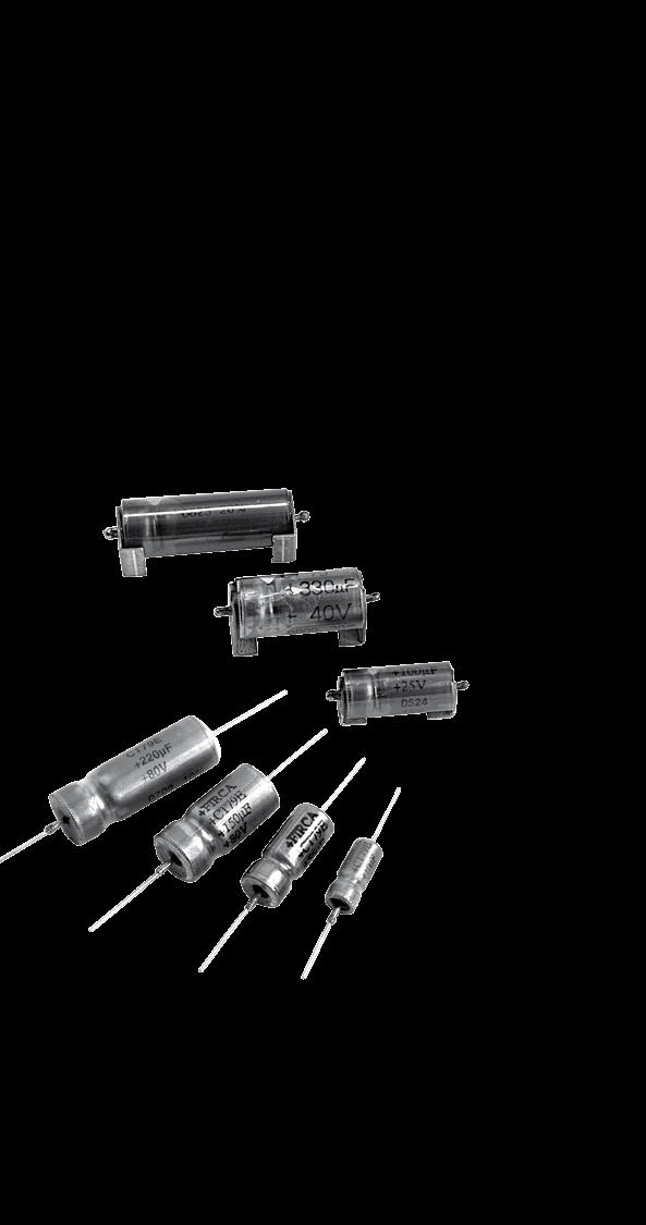
91 WET TANTALUM CAPACITORS Condensateurs tantale à électrolyte géliié
92 Electrical characteristics Caractéristiques électriques CAPACITANCE The capacitance is deined by a rated value (C R, indicated on the capacitor) and a tolerance (generally ±20%). The capacitance is measured at a 100 Hz frequency under a 0,1 to 1 V AC voltage and a 2,1 to 2,5 V bias (or 9 to 10V for U R 100 V). At room temperature, it must be in the range deined by the rated value and the tolerance. Capacitance change vs temperature : see typical curves below. Maximum changes are given, for each type, on the data sheets. CAPACITÉ La capacité est déinie par une valeur nominale (C R, indiquée sur le condensateur) et une tolérance (généralement de ±20%). La capacité est mesurée pour la plupart des modèles à une fréquence de 100 Hz (1 khz pour les modèles CTS 21-CTS 21E-CTC 21 et CTC 21E) avec une tension alternative de 0,1 à 1 V et une polarisation continue de 2,1 à 2,5 V. Elle doit être, à température ambiante, comprise dans la plage déinie par la capacité nominale et la tolérance. Variation en fonction de la tension de polarisation : négligeable CAPACITANCE CHANGE VS TEMPERATURE VARIATION EN FONCTION DE LA TEMPÉRATURE C/C +20% 0% 20% 40% 60% 80% T ( C) TOLERANCE (ON RATED CAPACITANCE) It deines, with the rated capacitance, the range in which the capacitance value must be at room temperature. e.g. : Rated capacitance : 100 µf Tolerance : 20% The measured capacitance must be between : (20% of 100) = 80 and (20% of 100) = 120 The standard tolerance for tantalum capacitors is 20%. TOLÉRANCE (SUR LA CAPACITÉ NOMINALE) Elle déinit, avec la capacité nominale, la plage dans laquelle doit être comprise la valeur de capacité à température ambiante. Exemple : Capacité nominale : 100 µf Tolérance : 20% La capacité mesurée doit alors être comprise entre : (20% de 100) = 80 et (20% de 100) = 120 La tolérance standard pour les condensateurs au tantale est de 20%. ±20% ± 20% ±20% ±20% ±20% ±20% The values (and multiples) that are indicated in bold characters (E6 serie) can be supplied with standard tolerances ±20% and ±10% (±5% on request). The values (and multiples) that are indicated in italics (E12 serie) can be only supplied with tolerance ±10% (±5% on request). Les valeurs indiquées en gras (et multiples), de la série E6, peuvent être fournies en tolérance standard de ±20% ou ±10% (sur demande ±5%). Les valeurs de la série E12 ( et multiples), en italique, sont fournies uniquement en tolérance ±10% (sur demande ±5%). 90
93 Electrical characteristics Caractéristiques électriques DIRECT DC VOLTAGE The rated voltage (U R ), indicated on the capacitor, is the maximum DC voltage which can be applied continuously between 55 C and. For the types which can be used up to 125 C, the voltage must be derated between and +125 C according to the following curve. TENSION CONTINUE DIRECTE ADMISIBLE La tension nominale (U R ), indiquée sur le condensateur, est la tension maximum d utilisation en régime permanent sur la plage de température de 55 C à. Pour les modèles spéciiés à 125 C, il faut appliquer, entre et +125 C un derating sur la tension, suivant le tableau ci-dessous. U R U C = 66% U R T ( C) The category voltage (U C ) is consequently the maximum DC voltage which can be applied continuously at +125 C. The surge voltage is the maximum voltage which can be applied for short periods. It is given for each type in the data sheet and is generally equal to 1,15 times U R between 55 C and and 1,15 times U C at +125 C. Tests are performed with charging periods of 30 seconds, through a 1000 Ω resistor, and discharging periods of 5min30s cycles are done. REVERSE VOLTAGE Capacitors in silver cases (CT 4 and CT 9 types) cannot withstand any reverse voltage : it will cause damage, more or less rapidly depending upon the voltage value. It is therefore necessary to be sure that the bias voltage is high enough to avoid that the AC voltage creates a reverse voltage (negative peak). Capacitors in tantalum cases (CT 79 type) can withstand 3 volts DC reverse voltage, at all the temperatures ( 55 C to 125 C). La tension de catégorie (U C ) est donc la tension maximum d utilisation en régime permanent à 125 C. La tension de pointe, ou surtension, est la tension maximum admissible en régime intermittent. Elle est déinie pour chaque modèle sur la iche technique et est généralement de 1,15 fois U R sur la plage 55 C et de 1,15 fois U C à +125 C. Les essais se font sur une durée de 30 secondes, au travers d une résistance de 1000 Ω, avec une décharge de 5 mn 30 s; 1000 cycles sont ainsi effectués. TENSION CONTINUE INVERSE ADMISSIBLE Les modèles en boîtier argent (de type CT 4 et CT 9) ne supportent aucune tension inverse : cela entraîne une détérioration plus ou moins rapide suivant la valeur de tension. Il faut donc s assurer que la tension continue de polarisation est sufisamment élevée pour que la composante alternative ne crée pas de tension inverse. Les modèles en boîtier tantale (de type CT 79) peuvent supporter une tension inverse maximum de 3 volts sur toute la plage de température ( 55 C à +125 C). 91
94 Electrical characteristics Caractéristiques électriques LEAKAGE CURRENT Leakage current is the residual current which lows through the capacitor after the charging time, under rated voltage. It is measured after a time not exceeding 5 minutes and is given in µa. It is equivalent to the insulation resistance of the capacitor and it must be as low as possible. Maximum leakage current is a function of capacitance and rated voltage values and is given, for each type, in the data sheets. LEAKAGE CURRENT CHANGE VS APPLIED VOLTAGE COURANT DE FUITE C est la valeur de courant résiduel traversant le condensateur lorsqu il est complètement chargé sous sa tension nominale (UR). Il est mesuré après un temps de charge ne devant pas excéder 5 minutes et est exprimé en µa. C est l équivalent de la résistance d isolement du condensateur et il doit donc être le plus faible possible. Le courant de fuite maximum est fonction des valeurs de capacité et de tension et est indiqué, pour chaque valeur, sur les tableaux des iches techniques. VARIATION COURANT DE FUITE EN FONCTION DE LA TENSION APPLIQUÉE Multiplier of leakage current / Multiplicateur du courant de fuite % U R - Percentage of rated voltage / Pourcentage tension nominale DISSIPATION FACTOR Dissipation factor is generally measured at the same time as the capacitance, with the same conditions. It is a function of the series resistance of the capacitor and the capacitance at low frequency. DF = ESR x C x 2p f At low frequency, the series resistance is the sum of an ohmic part (leads, contacts, MnO 2,...) and the dielectric losses. Dissipation factor is given in % and maximum limits are given for each type in the data sheets. TANGENTE DELTA (Tg ) ou facteur de dissipation Généralement mesurée simultanément avec la capacité (donc à 100 Hz ou 1 khz suivant les modèles), c est la représentation de la résistance série du condensateur en basse fréquence. Tg = RSE x C x 2p f En basse fréquence, la résistance série du condensateur est la somme d une partie ohmique (connexions, contacts, MnO 2,...) et des pertes diélectriques. La tangente de l angle de perte est exprimée en % et sa valeur maximum est indiquée sur les iches techniques pour chaque modèle. 92
95 Electrical characteristics Caractéristiques électriques EQUIVALENT SERIES RESISTANCE OR IMPEDANCE Equivalent circuit of a capacitor RÉSISTANCE SÉRIE ÉQUIVALENTE OU IMPÉDANCE Représentation d un condensateur en régime alternatif R R C L Z 1/ Cω Lω Impedance R : equivalent series resistance of the capacitor (leads,contacts, MnO 2, dielectric losses) L : inductance mainly due to the leads C : capacitance It is speciied at 100 Hz and 55 C and the formula for impedance is : Z = ( R 2 + ( Lq - 1/Cq) 2 ) It can be seen that : at low frequencies, impedance is a function of capacitance at high frequencies, impedance is a function of inductance at medium frequencies, it is a function of the ESR Maximum impedance : see data sheets. ESR CHANGE VS TEMPERATURE Variation de la RSE en fonction de la température RSE , 4 0, T ( C) Impédance R : résistance série équivalente du condensateur (ils, contacts, MnO 2, pertes diélectriques) L : inductance principalement due aux connexions C : capacité Elle est spéciiée à 100 Hz et 55 C et s écrit suivant l équation : Z = ( R 2 + ( Lq - 1/Cq) 2 ) On constate donc : qu en basse fréquence, l impédance est représentative de la capacité qu en haute fréquence, elle est liée à l inductance série qu en fréquence intermédiaire ( ex : 100 khz ), elle est peu différente de la valeur de la résistance série. Valeurs max d impédance : voir iches techniques. ESR CHANGE VS FREQUENCY Variation de la RSE en fonction de la fréquence RSE 0, 9 0, 8 0, 7 0, 6 0, 5 0, 4 0, 3 0, 2 0, k 10k 100 k f (Hz) 93
96 Electrical characteristics Caractéristiques électriques MAXIMUM RIPPLE CURRENT TYPES CT 79 - CT 79E - CT 79 HT200 - ST 79 Maximum ripple currents which are indicated in the data sheets are given for the following conditions : Temperature : Frequency : 40 khz Applied voltage : 0,66 U R If conditions are different, use the multipliers given in the table below to calculate the new maximum current. COURANT EFFICACE ADMISSIBLE MODèLES CT 79 - CT 79E - CT 79 HT200 - ST 79 Les valeurs maximum de courant eficace données dans les iches techniques sont applicables pour les conditions suivantes : Température : Fréquence : 40 khz Tension de polarisation : 0,66 UR Pour des conditions différentes, appliquer aux valeurs maximum indiquées les coeficients donnés dans le tableau ci-dessous. Frequency Fréquence 100 Hz 1 khz 10 khz 40 khz 100 khz Temperature 55 C 85 C 105 C 125 C 55 C 85 C 105 C 125 C 55 C 85 C 105 C 125 C 55 C 85 C 105 C 125 C 55 C 85 C 105 C 125 C Peak voltage in % of U R Tension de crête en % de U R 66% 0,6 0,6 0,46 0,27 0,72 0,72 0,55 0,32 0,88 0,88 0,68 0, ,77 0,45 1,1 1,1 0,85 0,5 70% 0,6 0,58 0,44 0,72 0,7 0,52 0,88 0,85 0,64 1 0,97 0,73 1,1 1,07 0,8 80% 0,6 0,52 0,35 0,72 0,62 0,42 0,88 0,76 0,52 1 0,87 0,59 1,1 0,96 0,65 90% 0,6 0,46 0,72 0,55 0,88 0,67 1 0,77 1,1 0,85 100% 0,6 0,39 0,72 0,45 0,88 0,55 1 0,63 1,1 0,69 TYPES CT 4 - CT 4E - CT 9 - CT 9E Maximum ripple currents which are indicated in the data sheets are given for the following conditions : frequency from 100 Hz to 100 khz and more temperature from 55 C to Correction vs temperature If the temperature is higher than 85 C, decrease linearly the maximum value from 100% at to 80% at +125 C. Correction vs frequency If frequency is lower than 100 Hz, apply the following multipliers to the maximum ripple currents : 75 Hz : 0,79 60 Hz : 0,65 50 Hz : 0,55 25 Hz : 0,55 OTHERS RULES (FOR ALL TYPES) the sum of the positive peak AC voltage and the DC bias voltage must be lower than the rated voltage. the negative peak must not create any reverse voltage (or maximum 3 volts for CT 79 and CT 79E types). because of the increase of the series resistance at low temperature, it is better to not apply directly the maximum ripple current but to increase this one gradually to raise the capacitor temperature. MODèLES CT 79 - CT 79E - ST 79 Les valeurs maximum de courant eficace données dans les iches techniques sont applicables pour des fréquences de 100 Hz à 100 khz et plus, et pour une plage de température de 55 C à. Correction en température Si la température est supérieure à 85 C, réduire linéairement la valeur maximum de 100% à à 80% à +125 C. Correction en fréquence Si la fréquence est inférieure à 100 Hz, appliquer à la valeur maximum les coeficients suivants : 75 Hz : 0,79 60 Hz : 0,65 50 Hz : 0,55 25 Hz : 0,55 AUTRES RèGLES (POUR TOUS MODèLES) la somme de la tension continue et de la crête positive ne devra pas dépasser la tension directe maximum du condensateur. la crête négative ne devra pas entraîner de tension inverse (ou 3 volts maximum pour les modèles CT79 et CT79E). du fait de l augmentation de la résistance série à froid, il est préférable de ne pas appliquer brutalement le courant eficace maximum, mais d augmenter graduellement celui-ci pour élever la température du condensateur. 94
97 Electrical characteristics Caractéristiques électriques CLIMATIC CHARACTERISTICS 1- CLIMATIC CATEGORY Climatic category deines the temperature range over which the capacitor can be used continuously, and also the number of days for the damp heat test (this test is performed periodically at 40 C with a 93% moisture rate). Note : it is necessary to derate the voltage for temperatures higher than 85 C (see page 89). 2- THERMAL SHOCKS - RAPID CHANGES OF TEMPERATURE This test is performed to check that the capacitors can withstand sudden temperature changes. The method which is used is the one with two chambers, one at 55 C, the other one at +125 C. Five cycles are performed, with 30min at low temperature and 30min at high temperature, during the periodical tests (30 cycles for CT 79 type). Electrical characteristics are measured after this test. 3 - DAMP HEAT TEST This test is performed during the periodical test, with the following conditions : Temperature : 40 C Humidity : 90 to 95% DC voltage : without Time : 21 or 56 days/jours Electrical characteristics are measured after this test. MECHANICAL CHARACTERISTICS 1 - VIBRATIONS This test is performed during the periodical test, with the following conditions : CT 9 - CT9 E types Method B4 Frequency : 10 to 2000 Hz Amplitude : 1,5mm or 196m/s2 Time : 6 hours CT 79 - CT 79E - CT 79 HT200 - ST 79 types Method B4 Frequency : 10 to 2000 Hz Amplitude : 3,5mm or 490m/s2 Time : 6 hours 2 - SHOCKS This test is performed just after the vibrations test, with the following conditions for all types : Acceleration : 981 m/s2 Pulse width : 6 ms Shape : 1/2 sinewave Number of shocks : 3 for each of the 3 directions CARACTÉRISTIQUES CLIMATIQUES 1- CATÉGORIE CLIMATIQUE La catégorie climatique déinit la plage de température sur laquelle le condensateur peut être utilisé de façon permanente, ainsi que le nombre de jours ixé pour l essai continu de chaleur humide ( réalisé périodiquement à 40 C avec une humidité relative de 93% ). Note : un derating doit être appliquée sur la tension au dessus de 85 C (voir page 89). 2- CHOCS THERMIQUES - VARIATIONS RAPIDES DE TEMPÉRATURE Cet essai permet de vériier l aptitude des condensateurs à supporter de brusques changements de température. La méthode utilisée est celle des deux chambres, l une à -55 C, l autre à +125 C. Cinq cycles de 30 mn à froid et 30 mn à chaud sont effectués, lors des essais périodiques (30 cycles pour le modèle CT 79). Les condensateurs sont mesurés électriquement après cet essai. 3 - ESSAI CONTINU DE CHALEUR HUMIDE Cet essai est réalisé dans le cadre des essais périodiques avec les conditions suivantes : Température : 40 C Humidité relative : 90 à 95% Tension : sans Durée : 21 ou 56 jours Les condensateurs sont ensuite mesurés électriquement. CARACTÉRISTIQUES MÉCANIQUES 1 - VIBRATIONS Cette épreuve est effectuée lors des essais périodiques avec les sévérités suivantes : s CT 9 - CT 9E Méthode B4 Fréquence : 10 à 2000 Hz Amplitude : 1,5mm ou 196m/s 2 Durée : 6 heures s CT 79 - CT 79E - CT 79 HT200 - ST 79 Méthode B4 Fréquence : 10 à 2000 Hz Amplitude : 3,5mm ou 490m/s 2 Durée : 6 heures 2 - CHOCS Cet essai est effectué après l épreuve de vibrations avec les sévérités suivantes pour tous les modèles : Accélération : 981 m/s 2 Durée de l impulsion : 6 ms Forme : 1/2 sinusoïde Nombre de chocs : 3 dans chacune des 3 directions 95
98 General characteristics Caractéristiques générales RELIABILITY Reliability of a component can be deined as its probability to work without any failure, in deined conditions and during a ixed time. Reliability is not therefore only a function of the component quality, but also of the application and environmental conditions. The parameter which is the most commonly used for the reliability is the failure rate in time, generally expressed in % per 1000 hours. CALCULATION OF A COMPONENT FAILURE RATE USED IN AN EQUIPMENT The calculation method on the next page uses parmeters which are given by the CNET (Centre National d Etude des Télécommunications) in its Reliability Data Book (RDF 1993). The failure rate is calculated with parameters which are function of the capacitor (capacitance, case type, approvals, high surge current test) and others ones which are representative of application conditions (voltage, temperature, resistance in serie, environmental conditions). Example : CT 79E 2200 µf - 6,3 V used under 3 volts, at 40 C, in a satellite in orbit : p t = 1,2 p V = 1,38 p C = 1,4 p E = 0,5 p q = 1 l = 3 x 1,2 x 1,38 x 1,4 x 0,5 x /h = 3, /h = 0,00035 % defects/1000 hours FIABILITE La iabilité d un composant peut se déinir comme la probabilité de fonctionnement sans défaillance de celui-ci, dans des conditions déterminées et pour une durée déinie. Elle n est donc pas seulement liée à sa propre qualité, mais également aux conditions d utilisation et d environnement. Le paramètre le plus utilisé pour représenter la iabilité est le taux de défaillance par unité de temps, généralement exprimé en % par 1000 heures. CALCUL DU TAUX DE DÉFAUT D UN COMPOSANT DANS UN ÉQUIPEMENT La méthode de calcul de la page suivante reprend les éléments donnés par le CNET (Centre National d Etude des Télécommunications) dans son Recueil de Données de Fiabilité (RDF 1993). Le taux de défaut est calculé à partir de paramètres qui sont fonction du composant (capacité, type de boîtier, qualiication, garantie en charge/décharge) et d autres qui sont fonction des conditions d utilisation (tension, température, résistance série, environnement). Exemple : CT 79E 2200 µf - 6,3 V utilisé à 3 volts, 40 C, sur un satellite en orbite : p t = 1,2 p V = 1,38 p C = 1,4 p E = 0,5 p q = 1 l = 3 x 1,2 x 1,38 x 1,4 x 0,5 x 1/10 9 /h = 3, /h = 0,00035 % défaut/1000 heures 96
99 General characteristics Caractéristiques générales p t = TEMPERATURE INFLUENCE p t = Inluence de la température t 100 p V = INFLUENCE OF APPLIED VOLTAGE VS RATED VOLTAGE p V = Inluence de la tension selon la tension nominale V Formula : p t = exp (1,8.( t / tm) 2 ) Formule with : avec t = using temperature / température d utilisation tm = maximum temperature / température maximale Curve for tm = 125 C / Tableau pour tm = 125 C p C = INFLUENCE OF CAPACITANCE 3,3 µf p C = 0,9 20 µf p C = 1, µf p C = 1, µf p C = 1,4 p E = INFLUENCE OF CIRCUIT RESISTOR IN SERIE Satellite in orbit p E = 0,5 Ground ; stationary ; protected p E = 1 Ground ; stationary ; non protected p E = 2,5 Ground ; mobile ; soft conditions p E = 6 Aircraft ; soft conditions p E = 6 Ship ; soft conditions p E = 6 Ground ; mobile ; hard conditions p E = 8 Ship ; hard conditions p E = 10 Aircraft ; hard conditions p E = 15 Satellite ; launching p E = 20 p q = INFLUENCE OF QUALIFICATION Products approved to CECC p q = 1,0 Others products p q = 2,0 T ( C) Formula : p V = exp ( ( r / 0,85) 2 ) Formule peak voltage/tension de crête r = rated voltage/tension nominale Curve p V = f (r)/tableau p V = f (r) p C = INFLUENCE DE LA CAPACITÉ 3,3 µf p C = 0,9 20 µf p C = 1, µf p C = 1, µf p C = 1,4 p E = INFLUENCE DE L ENVIRONNEMENT Satellite sur orbite p E = 0,5 Sol ; fixe ; protégé p E = 1 Sol ; fixe ; non protégé p E = 2,5 Sol ; mobile ; favorable p E = 6 Avion ; favorable p E = 6 Bateau ; favorable p E = 6 Sol ; mobile ; défavorable p E = 8 Bateau ; défavorable p E = 10 Avion ; défavorable p E = 15 Satellite ; lancement p E = 20 p q = INFLUENCE DE LA QUALIFICATION Produits CECC p q = 1,0 Autres p q = 2,0 97
100 General characteristics Caractéristiques générales PRODUCT SAFETY INFORMATION SHEET This should read in conjunction with the Product Data Sheet/Speciication. Failure to observe the ratings, and the information on this sheet may result in a safety hazard. 1. MATERIAL CONTENT Wet Tantalum Capacitors contain hazardous materials. The operating section contains : Liquid Electrolyte - Gelled Dilute Sulphuric Acid. Solid Tantalum Anode The device consists of solder coated terminal wires and the materials listed below : Silver Case or Tantalum Case Silicon Rubber O Rings P.T.F.E. Spacers Filled epoxy resin end cap on Silver Case Product. 2. PHYSICAL FORM These Capacitors are physically small and are cylindrical with axial leads. 3. INTRINSIC PROPERTIES 3.1 Operating Silver Cased Product These capacitors will operate satisfactorily providing the sum of the applied d.c. and the peak a.c. ripple voltage does not exceed the rated d.c. voltage. There must be no reversal of polarity. The maximum ripple currents and voltages and d.c. polarising voltages are speciied in the data sheets. Tantalum Cased devices will stand up to 3 V DC reverse for short periods of time. A reverse application of the rated voltage will result in loss of capacitance, early short circuit failure and may result in ire or explosion. It may also cause consequential failure of other associated components in circuit, e.g. diodes, transformers, etc. 3.2 Non-Operating Wet Tantalum capacitors contain electrolyte which is a conducting material. If electrolyte leaks onto a printed circuit board or similar insulated support, short circuits can be caused. All electrolytes are corrosive to some extent. No electrolyte should be allowed to come in contact with the skin, eyes, etc., and if they do appropriate medical treatment should be applied. INFORMATION SUR LA SÉCURITÉ Vous devez lire ces informations en tenant compte de la iche technique, des normes et spéciications du produit. Les remarques et informations suivantes doivent aboutir à la diminution des accidents. 1. LES CONSTITUANTS DU COMPOSANT Les condensateurs tantale à électrolyte géliié contiennent des substances dangereuses. Le composant contient : De l électrolyte à base d H2SO4 Une anode de tantale fritté Le composant est constitué de connexions étamées ainsi que des constituants cités ci-dessous : argent ou boîtier tantale Joint élastomère Joint P.T.F.E. Résine époxy de protection sur boîtier argent 2. ASPECT Ces condensateurs sont de petite taille, cylindrique, avec des connexions axiales. 3. PROPRIÉTÉS DES CONDENSATEURS 3.1 Fonctionnement des condensateurs Ces condensateurs fonctionneront de manière satisfaisante à condition que la somme de la tension continue et de la crête positive ne dépasse pas la tension directe maximum du condensateur. Aucune tension inverse n est permise pour les modèles en boîtier argent. Les valeurs maximum de courant eficace, de tension de service et de tension de pointe sont indiquées dans les iches techniques. Les modèles en boîtier tantale peuvent supporter une tension inverse maximale de 3 volts sur une courte durée. L application inverse de la tension aboutira à une perte de capacité, à une défaillance précaire du diélectrique, résultant d un court-circuit et d une explosion ou d un feu. Cela peut aussi entraîner des défaillances au niveau des autres composants du circuit, par exemple, au niveau des diodes, des transformateurs, etc. 3.2 Non-fonctionnement Les condensateurs tantale à électrolyte géliié contiennent de l électrolyte qui est une matière conductrice. Si l électrolyte se répand sur le circuit imprimé ou sur un support isolant similaire, des court-citcuits peuvent être provoqués. Dans une certaine mesure, tous les électrolytes sont corrosifs. Aucun électrolyte ne doit être en contact avec la peau, les yeux, etc. Si cela devait arriver, un traitement médical devrait être envisagé au plus vite. 98
101 General characteristics Caractéristiques générales Applicable for types see below : General purpose : CT 79 - CT 79 HT200 - ST 79 Extended ranges : CT 79E CONSTRUCTION Applicables pour les modèles suivants : Usage général : CT 79 - CT 79 HT200 - ST 79 Gammes étendues : CT 79E CONSTRUCTION Ring seal Joint circulaire Case to seal laser welding Soudure laser boîtier-traversée Tantalum-glass-tantalum seal Traversée tantale-verre-tantale Tantalum wire-tube-nickel wire welding Soudure fil tantale-canon-fil nickel Metal case métallique Tantalum cathode Cathode tantale PTFE spacer Cale en téflon Tantalum wire Fil de tantale PTFE bush Bouchon de téflon Wet or gelled electrolyte Electrolyte gélifié Sintered tantalum anode Anode de tantale frittée MARKING MARQUAGE + Positive mark + Repère du positif Voltage/Tension FIRCA CT V µf % Brand/Marquage / Capacitance/Capacité Tolerance Tolérance Date code = year (année) : 2 digits week (semaine) : 2 digits PACKAGING In cardboard boxes CONDITIONNEMENT En boîtes carton 99
102 General characteristics Caractéristiques générales Applicable for types see below : Glass metal seal - standard range : CT 9 Glass metal seal - extended range : CT 9E : Epoxy end seal - standard range : CT 4 Epoxy end seal - extended range : CT 4E CONSTRUCTION Applicables pour les modèles suivants : Traversée étanche - gamme standard : CT 9 Traversée étanche - gamme étendue : CT 9E Fermeture joint et résine - gamme standard : CT 4 Fermeture joint et résine - gamme étendue : CT 4E CONSTRUCTION Ring seal Joint circulaire Case to seal soldering Soudure boîtier-traversée Tantalum-glass-metal seal Traversée tantale-verre-métal Tantalum wire-tube-nickel wire welding Soudure fil tantale-canon-fil nickel CT 9 - CT 9E Silver case en argent PTFE spacer Cale en téflon Tantalum wire Fil de tantale PTFE bush Bouchon en téflon Wet or gelled electrolyte Electrolyte gélifié Sintered tantalum anode Anode de tantale frittée Ring seal Joint circulaire Case crimping on elastomer seal Sertissage boîtier sur joint viton Tantalum-glass-metal seal Traversée tantale-verre-métal Tantalum wire-tube-nickel wire welding Soudure fil tantale-canon-fil nickel CT 4 - CT 4E Silver case en argent PTFE spacer Cale en téflon Tantalum wire Fil nickel (positif) PTFE bush Bouchon en téflon Wet or gelled electrolyte Electrolyte gélifié Sintered tantalum anode Anode de tantale frittée MARKING MARQUAGE + Positive mark + Repère du positif Voltage/Tension FIRCA CT V µf % Brand/Marquage / Capacitance/Capacité Tolerance Tolérance Date code = year (année) : 2 digits week (semaine) : 2 digits PACKAGING In cardboard boxes CONDITIONNEMENT En boîtes carton 100
103 ESCC 3003/005 - CLR79 CT 79 (T3T - 40AW) CT 79E (ST3T - 40AW) Wet tantalum capacitors Hermetically sealed tantalum cases Axial leads Polarized types Condensateurs tantale à électrolyte géliié s tantale hermétiques Sorties axiales Polarisés ELECTRICAL AND CLIMATIC CHARACTERISTICS CT 79 CT 79E CARACTÉRISTIQUES ÉLECTRIQUES ET CLIMATIQUES Detail speciication CECC CECC Spéciication particulière CECC CECC CECC CECC MIL-PRF /22 MIL-PRF-39006/25 Operating temperature 55 C +125 C 55 C +125 C Température d utilisation Damp heat 56 days/jours 56 days/jours Chaleur humide Capacitance range 1,7µF µf 5,6µF µf Gamme de capacité Tolerance 20%...10% 20%...10% Tolérance Voltage range 6V...125V 6V...150V Gamme de tension Max. capacitance change 55 C see table/voir tableau see table/voir tableau C / C maximum à 55 C Max. capacitance change see table/voir tableau see table/voir tableau C / C maximum à Max. capacitance change +125 C see table/voir tableau see table/voir tableau C / C maximum à +125 C Maximum DF at see table/voir tableau see table/voir tableau Tg maximum à Maximum DF at = lim20 C = lim20 C Tg maximum à Maximum DF at +125 C = lim20 C = lim20 C Tg maximum à +125 C Max. impedance (100 Hz) at 55 C see table/voir tableau see table/voir tableau Impédance max. (100 Hz) à 55 C Max. leakage current at see table/voir tableau see table/voir tableau Courant de fuite max. à Max. leakage current at see table/voir tableau see table/voir tableau Courant de fuite max. à Max. leakage current at +125 C = lim = lim Courant de fuite max. à +125 C Max. ripple current 40 khz see table/voir tableau see table/voir tableau Courant eff. max à 40 khz Max. reverse voltage at 3 volts 3 volts Tension inverse max. à Max. reverse voltage at 3 volts 3 volts Tension inverse max. à Max. reverse voltage at +125 C 3 volts 3 volts Tension inverse max. à +125 C Max. surge voltage at 1,15 x U R 1,15 x U R Surtension max. à Max. surge voltage at +125 C 1,15 x U C 1,15 x U C Surtension max. à +125 C DIMENSIONS (mm) DIMENSIONS (mm) Case code Dimensions with insulating sleeve Dimensions avec gaine isolante L max D max d +10% 0,05 A 18 5,6 0,6 B 23 7,4 0,6 C 26 10,1 0,6 D 34 10,1 0,6 MARKING, PACKAGING, CONSTRUCTION : see general characteristics 25 min. d L 25 min. D MARQUAGE, CONDITIONNEMENT, CONSTRUCTION : voir caractéristiques générales 101
104 CT 79 - CT 79 SMD / CMS (Standard range/gamme standard) STANDARD RATINGS - ELECTRICAL CHARACTERISTICS Capacitance Capacité 100 Hz (µf) Case (code) 55 C Capacitance maximum change Variation maximum de le capacité +125 C Tang. d max. VALEURS STANDARD - CARACTÉRISTIQUES ÉLECTRIQUES Max. Impedance Impédance max. (Ω) Max. I leak I fuite max. Irms Max. Ieff. max. 40 khz (ma) Rated voltage / Tension nominale () 6 V - 6,3 V - Category voltage / Tension de catégorie (+125 C) 4 V 30 A CT A CT B CT B CT , B CT , C CT , C CT , D CT D CT Rated voltage / Tension nominale () 8 V - Category voltage / Tension de catégorie (+125 C) 5 V 25 A CT , , A CT B CT , B CT C CT , C CT , D CT Rated voltage / Tension nominale () 10 V - Category voltage / Tension de catégorie (+125 C) 6,3 V 20 A CT , A CT B CT B CT B CT C CT C CT , D CT D CT D CT Rated voltage / Tension nominale () 15 V - 16 V - Category voltage / Tension de catégorie (+125 C) 10 V 15 A CT , A CT B CT B CT C CT C CT C CT , C CT D CT D CT D CT Rated voltage / Tension nominale () 25 V - Category voltage / Tension de catégorie (+125 C) 16 V 10 A CT A CT , B CT B CT C CT C CT D CT D CT D CT D CT Rated voltage / Tension nominale () 30 V - Category voltage / Tension de catégorie (+125 C) 20 V 8 A CT A CT B CT , B CT C CT , C CT D CT
105 (Standard range/gamme standard) CT 79 - CT 79 SMD / CMS STANDARD RATINGS - ELECTRICAL CHARACTERISTICS Capacitance Capacité 100 Hz (µf) Case (code) 55 C Capacitance maximum change Variation maximum de le capacité +125 C Tang. d max. VALEURS STANDARD - CARACTÉRISTIQUES ÉLECTRIQUES Max. Impedance Impédance max. (Ω) Max. I leak I fuite max. Irms Max. Ieff. max. 40 khz (ma) Rated voltage / Tension nominale () 40 V - Category voltage / Tension de catégorie (+125 C) 25 V 12 A CT B CT C CT D CT Rated voltage / Tension nominale () 50 V - Category voltage / Tension de catégorie (+125 C) 30 V 5 A CT A CT B CT , B CT C CT , C CT D CT Rated voltage / Tension nominale () 60 V - 63 V - Category voltage / Tension de catégorie (+125 C) 40 V 4 A CT , ,2 A CT B CT , B CT C CT , C CT , D CT D CT Rated voltage / Tension nominale () 75 V - 80 V - Category voltage / Tension de catégorie (+125 C) 50 V 3,5 A CT , ,8 A CT B CT B CT C CT , C CT , C CT D CT D CT D CT D CT Rated voltage / Tension nominale () 100 V - Category voltage / Tension de catégorie (+125 C) 65 V 2,5* A CT ,7 A CT * B CT B CT , C CT C CT C CT C CT C CT D CT D CT D CT Rated voltage / Tension nominale () 125 V - Category voltage / Tension de catégorie (+125 C) 85 V 1,7* A CT ,2 A CT ,7 A CT ,3 A CT ,6 A CT , ,9 A CT , * B CT B CT B CT * C CT C CT C CT D CT
106 CT 79E - CT 79E SMD / CMS (Extended range/gamme étendue) STANDARD RATINGS - ELECTRICAL CHARACTERISTICS Capacitance Capacité 100 Hz (µf) Case (code) 55 C Capacitance maximum change Variation maximum de le capacité +125 C Tang. d max. VALEURS STANDARD - CARACTÉRISTIQUES ÉLECTRIQUES Max. Impedance Impédance max. (Ω) Max. I leak I fuite max. Irms Max. Ieff. max. 40 khz (ma) Rated voltage / Tension nominale () 6 V - 6,3 V - Category voltage / Tension de catégorie (+125 C) 4 V 120 A CT79E , A CT79E A CT79E * A CT79E B CT79E B CT79E * B CT79E C CT79E D CT79E Rated voltage / Tension nominale () 8 V - Category voltage / Tension de catégorie (+125 C) 5 V 120 A CT79E , * A CT79E B CT79E , * B CT79E * C CT79E * D CT79E Rated voltage / Tension nominale () 10 V - Category voltage / Tension de catégorie (+125 C) 6,3 V 68 A CT79E , A CT79E A CT79E * A CT79E B CT79E B CT79E B CT79E B CT79E C CT79E * B CT79E C CT79E C CT79E C CT79E D CT79E D CT79E * D CT79E Rated voltage / Tension nominale () 15 V - 16 V - Category voltage / Tension de catégorie (+125 C) 10 V 47 A CT79E , A CT79E , * A CT79E * A CT79E B CT79E B CT79E B CT79E C CT79E * B CT79E C CT79E C CT79E C CT79E D CT79E D CT79E D CT79E * out of CECC range * hors gamme CECC 104
107 (Extended range/gamme étendue) CT 79E - CT 79E SMD / CMS STANDARD RATINGS - ELECTRICAL CHARACTERISTICS Capacitance Capacité 100 Hz (µf) Case (code) 55 C Capacitance maximum change Variation maximum de le capacité +125 C Tang. d max. VALEURS STANDARD - CARACTÉRISTIQUES ÉLECTRIQUES Max. Impedance Impédance max. (Ω) Max. I leak I fuite max. Irms Max. Ieff. max. 40 khz (ma) Rated voltage / Tension nominale () 25 V - Category voltage / Tension de catégorie (+125 C) 16 V 27 A CT79E , A CT79E , A CT79E A CT79E * A CT79E B CT79E B CT79E B CT79E C CT79E * B CT79E C CT79E C CT79E * C CT79E C CT79E D CT79E D CT79E D CT79E Rated voltage / Tension nominale () 30 V - Category voltage / Tension de catégorie (+125 C) 20 V 25 A CT79E , A CT79E * A CT79E * A CT79E B CT79E B CT79E B CT79E * B CT79E C CT79E C CT79E C CT79E C CT79E C CT79E * C CT79E D CT79E Rated voltage / Tension nominale () 40 V - Category voltage / Tension de catégorie (+125 C) 25 V 15 A CT79E A CT79E , A CT79E , * A CT79E B CT79E B CT79E B CT79E C CT79E C CT79E C CT79E D CT79E D CT79E Rated voltage / Tension nominale () 50 V - Category voltage / Tension de catégorie (+125 C) 30 V 18 A CT79E , A CT79E * A CT79E B CT79E * B CT79E , C CT79E * D CT79E D CT79E D CT79E D CT79E * out of CECC range * hors gamme CECC 105
108 CT 79E - CT 79E SMD / CMS (Extended range/gamme étendue) STANDARD RATINGS - ELECTRICAL CHARACTERISTICS VALEURS STANDARD - CARACTÉRISTIQUES ÉLECTRIQUES Capacitance Capacité 100 Hz (µf) Case (code) 55 C Capacitance maximum change Variation maximum de le capacité +125 C Tang. d max. Max. Impedance Impédance max. (Ω) Max. I leak I fuite max. Irms Max. Ieff. max. 40 khz (ma) Rated voltage / Tension nominale () 60 V - 63 V - Category voltage / Tension de catégorie (+125 C) 40 V 10 A CT79E A CT79E A CT79E * A CT79E B CT79E B CT79E B CT79E * B CT79E C CT79E C CT79E C CT79E D CT79E D CT79E Rated voltage / Tension nominale () 75 V - 80 V - Category voltage / Tension de catégorie (+125 C) 50 V 8,2 A CT79E , A CT79E * A CT79E , B CT79E , B CT79E B CT79E , B CT79E * B CT79E C CT79E C CT79E C CT79E C CT79E D CT79E , D CT79E * D CT79E Rated voltage / Tension nominale () 100 V - Category voltage / Tension de catégorie (+125 C) 65 V 5,6 A CT79E * A CT79E , B CT79E B CT79E B CT79E C CT79E C CT79E , D CT79E * D CT79E Rated voltage / Tension nominale () 125 V - Category voltage / Tension de catégorie (+125 C) 85 V 6,8* A CT79E B CT79E * B CT79E , C CT79E C CT79E , D CT79E D CT79E Rated voltage / Tension nominale () 150 V - Category voltage / Tension de catégorie (+125 C) 100 V 2,5* A CT79E ,3* A CT79E * B CT79E * B CT79E * C CT79E * C CT79E * D CT79E * D CT79E * out of CECC range NOTE Voltage 6V, 8V, 15V, 30V, 50V, 60V and 75V concern the MIL standard range. NOTE Les tensions 6V, 8V, 15V, 30V, 50V, 60V et 75V concernent la gamme MIL. * hors gamme CECC 106


109 CT 79 SMD / CMS CT 79E SMD / CMS Wet tantalum capacitors Hermetically sealed tantalum cases for surface mount SMD Axial leads Polarized types Condensateurs tantale à électrolyte géliié s tantale hermétiques CMS pour montage en surface Sorties axiales Polarisés ELECTRICAL AND CLIMATIC CHARACTERISTICS CARACTÉRISTIQUES ÉLECTRIQUES ET CLIMATIQUES CT 79 SMD / CMS CT 79E SMD / CMS Detail speciication CECC CECC Spéciication particulière CECC CECC CECC CECC MIL-PRF /22 MIL-PRF-39006/25 Operating temperature 55 C +125 C 55 C +125 C Température d utilisation Damp heat 56 days/jours 56 days/jours Chaleur humide Capacitance range 1,7µF µf 5,6µF µf Gamme de capacité Tolerance 20%...10% 20%...10% Tolérance Voltage range 6V...125V 6V...125V Gamme de tension Max. capacitance change 55 C see table/voir tableau see table/voir tableau C / C maximum à 55 C Max. capacitance change see table/voir tableau see table/voir tableau C / C maximum à Max. capacitance change +125 C see table/voir tableau see table/voir tableau C / C maximum à +125 C Maximum DF at see table/voir tableau see table/voir tableau Tg maximum à Maximum DF at = lim20 C = lim20 C Tg maximum à Maximum DF at +125 C = lim20 C = lim20 C Tg maximum à +125 C Max. impedance (100 Hz) at 55 C see table/voir tableau see table/voir tableau Impédance max. (100 Hz) à 55 C Max. leakage current at see table/voir tableau see table/voir tableau Courant de fuite max. à Max. leakage current at see table/voir tableau see table/voir tableau Courant de fuite max. à Max. leakage current at +125 C = lim = lim Courant de fuite max. à +125 C Max. ripple current 40 khz see table/voir tableau see table/voir tableau Courant eff. max à 40 khz Max. reverse voltage at 3 volts 3 volts Tension inverse max. à Max. reverse voltage at 3 volts 3 volts Tension inverse max. à Max. reverse voltage at +125 C 3 volts 3 volts Tension inverse max. à +125 C Max. surge voltage at 1,15 x U R 1,15 x U R Surtension max. à Max. surge voltage at +125 C 1,15 x U C 1,15 x U C Surtension max. à +125 C DIMENSIONS (mm) DIMENSIONS (mm) Case code B max F max H max E ±0,4 C max G max Ø max Ø G G A 13,5 4,0 4,8 3,8 7,5 2,0 5,8 B 18,5 4,0 5,9 5,3 9,5 2,0 7,4 C 21,5 4,0 7,5 8,4 12,5 2,0 10,1 D 29,5 4,0 7,5 8,4 12,5 2,0 10,1 MARKING, PACKAGING, CONSTRUCTION : see general characteristics X X MARQUAGE, CONDITIONNEMENT, CONSTRUCTION : voir caractéristiques générales 107
110 ST 79 ESCC 3003/006 - cases C & D Wet tantalum capacitors Hermetically sealed tantalum cases Very high capacitance Very low ESR High ripple current Axial leads Polarized types Condensateurs tantale à électrolyte géliié s tantale hermétiques Très forte capacité Très faible RSE Fort courant eficace Sorties axiales Polarisés ELECTRICAL AND CLIMATIC CHARACTERISTICS ST 79 Detail speciication DSCC DWG No Spéciication particulière ESCC 3003/006 CARACTÉRISTIQUES ÉLECTRIQUES ET CLIMATIQUES Operating temperature 55 C +125 C Température d utilisation Damp heat 56 jours / days Chaleur humide Capacitance range 10 µf µf Gamme de capacité Tolerance 20%...10% Tolérance Voltage range 25V...125V Gamme de tension Max. capacitance change 55 C see table/voir tableau C / C maximum à 55 C Max. capacitance change see table/voir tableau C / C maximum à Max. capacitance change +125 C see table/voir tableau C / C maximum à +125 C Maximum DF at see table/voir tableau Tg maximum à Maximum DF at = lim20 C Tg maximum à Maximum DF at +125 C = lim20 C Tg maximum à +125 C Max. impedance (100 Hz) at 55 C see table/voir tableau Impédance max. (100 Hz) à 55 C Max. leakage current at see table/voir tableau Courant de fuite max. à Max. leakage current at see table/voir tableau Courant de fuite max. à Max. leakage current at +125 C = lim Courant de fuite max. à +125 C Max. RSE at 120 Hz +25 C see table/voir tableau ESR maximum (120 Hz) à +25 C Max. RSE at 40 khz +25 C see table/voir tableau ESR maximum (40 khz) à +25 C Max. ripple current 40 khz see table/voir tableau Courant eff. max à 40 khz Reverse voltage No continuous reverse voltage reverse voltage are acceptable under some conditions U REV 1,5 V and It 0,05 A second The repetition rate of the reverse voltage surges is < 10 Hz Pas de tension inverse permise en continu Des inversions de tension sont acceptables sous conditions U INV 1,5 V et It 0,05 A seconde La fréquence de répétition est < 10 Hz Tension inverse Max. surge voltage at 1,15 x U R Surtension max. à Max. surge voltage at +125 C 1,15 x U C Surtension max. à +125 C DIMENSIONS (mm) Case code Dimensions with insulating sleeve Dimensions avec gaine isolante L max D max d +10% 0,05 A 18 5,6 0,6 B 23 7,4 0,6 C 26 10,1 0,6 D 34 10,1 0,6 DIMENSIONS (mm) 25 min. X 32,6 7,4 0,6 L d 25 min. D MARKING, PACKAGING, CONSTRUCTION : see general characteristics MARQUAGE, CONDITIONNEMENT, CONSTRUCTION : voir caractéristiques générales 108
111 ST 79 STANDARD RATINGS - ELECTRICAL CHARACTERISTICS Capacitance Capacité 100 Hz (µf) Case (code) Capacitance maximum change Variation maximum de le capacité 55 C +125 C Tang. d max. Max. Impedance Impédance max. (Ω) VALEURS STANDARD - CARACTÉRISTIQUES ÉLECTRIQUES Max. I leak I fuite max. Irms Max. Ieff. max. 40 khz (ma) Rated voltage / Tension nominale () 25 V - Category voltage / Tension de catégorie (+125 C) 15 V 120 A ST ,3 0, B ST ,8 0, C ST ,6 0, D ST ,5 0,20 Rated voltage / Tension nominale () 30 V - Category voltage / Tension de catégorie (+125 C) 20 V 100 A ST ,3 0, B ST ,8 0, C ST ,7 0, D ST ,6 0,20 Rated voltage / Tension nominale () 40 V - Category voltage / Tension de catégorie (+125 C) 25 V 1000 D ST ,7 0,25 Rated voltage / Tension nominale () 50 V - Category voltage / Tension de catégorie (+125 C) 30 V 68 A ST ,5 0, B ST ,9 0, C ST ,7 0, D ST ,6 0, D ST ,7 0,27 Rated voltage / Tension nominale () 60 V - Category voltage / Tension de catégorie (+125 C) 40 V 47 A ST ,0 0, B ST ,1 0, C ST ,9 0, D ST ,8 0, D ST ,7 0,27 Rated voltage / Tension nominale () 63 V - Category voltage / Tension de catégorie (+125 C) 40 V 500 D ST ,8 0,30 Rated voltage / Tension nominale () 75 V - Category voltage / Tension de catégorie (+125 C) 50 V 33 A ST ,5 1, C ST ,0 0, D ST ,9 0,30 Rated voltage / Tension nominale () 100 V - Category voltage / Tension de catégorie (+125 C) 65 V 15 A ST ,5 1,40 68 B ST ,1 0, C ST ,6 0, D ST ,2 0,40 Rated voltage / Tension nominale () 125 V - Category voltage / Tension de catégorie (+125 C) 85 V 10 A ST ,5 2,10 47 B ST ,3 0,90 90 X ST ,3 0, C ST ,8 0, D ST ,6 0, Hz (Ω) Max. ESR RSE max. 40 khz (Ω) 109
112 CT 79 HT200 CT 79E HT200 Wet tantalum capacitors Hermetically sealed tantalum cases Axial leads Polarized types Condensateurs tantale à électrolyte géliié s tantale hermétiques Sorties axiales Polarisés LEAKAGE CURRENT : The improvements made on wet tantalum products allow us to have the same leakage currents at 200 C on these products than at 125 C with standard products. COURANT DE FUITE : Les améliorations apportées sur les performances des produits en tantale géliié nous permettent aujourd hui d avoir un courant de fuite à 200 C similaire aux performances aux températures standard. ELECTRICAL AND CLIMATIC CHARACTERISTICS Product manufactured from components approved to detail speciications CARACTÉRISTIQUES ÉLECTRIQUES ET CLIMATIQUES CT 79 HT200 CT 79E HT200 CECC CECC Fabrication à partir de composant CECC CECC homologués suivant spéciications CECC CECC particulières Operating temperature 55 C +200 C 55 C +200 C Température d utilisation Damp heat 56 jours/days 56 jours/days Chaleur humide Capacitance range 1,7µF 1200µF 5,6µF 2200µF Gamme de capacité Tolerance 20%...10%...5% 20%...10%...5% Tolérance Voltage range 6V 125V 6V 150V Gamme de tension Max capacitance change at -55 C voir / see / table voir / see / table C/ C maximum à -55 C Max capacitance change at voir / see / table voir / see / table C / C maximum à Max capacitance change at +125 C voir / see / table voir / see / table C / C maximum à +125 C Maximum DF at voir / see / table voir / see / table Tg maximum à Maximum DF at = lim20 C = lim20 C Tg maximum à Maximum DF at +125 C = lim20 C = lim20 C Tg maximum à +125 C Max. Impedance (100Hz) at 55 C voir / see / table voir / see / table Impéd. Max. (100Hz) à -55 C Max leakage current at voir / see / table voir / see / table Courant de fuite max à Max leakage current at voir / see / table voir / see / table Courant de fuite max à Max leakage current at +125 C = lim85 C = lim85 C Courant de fuite max à +125 C Max leakage current at +175 C = 1,1 x lim85 C = 1,1 x lim85 C Courant de fuite max à +175 C Max leakage current at +200 C = 1,1 x lim85 C = 1,1 x lim85 C Courant de fuite max à +200 C Max. ripple current 40 khz voir / see / table voir / see / table Courant eff.max à 40 khz Max reverse voltage at 3 volts 3 volts Tension inverse max à Max reverse voltage at 3 volts 3 volts Tension inverse max à Max reverse voltage at +125 C 3 volts 3 volts Tension inverse max à +125 C Max surge voltage at 1,15 x Un (85 C) 1,15 x Un (85 C) Surtension max à Max surge voltage at +125 C 1,15 x Un (125 C) 1,15 x Un (125 C) Surtension max à +125 C DIMENSIONS (mm) DIMENSIONS (mm) Case code Dimensions with insulating sleeve Dimensions avec gaine isolante L max D max d +10% 0,05 A 18 5,6 0,6 B 23 7,4 0,6 C 26 10,1 0,6 D 34 10,1 0,6 25 min. d L 25 min. D MARKING, PACKAGING, CONSTRUCTION : see general characteristics MARQUAGE, CONDITIONNEMENT, CONSTRUCTION : voir caractéristiques générales 110
113 (Standard range/gamme standard) CT 79 HT200 STANDARD RATINGS - ELECTRICAL CHARACTERISTICS Capacitance Capacité 100 Hz (µf) Case Capacitance maximum change Variation maximum de le capacité Tang. d max. VALEURS STANDARD - CARACTÉRISTIQUES ÉLECTRIQUES Max. Impedance Impédance max. Max. I leak I fuite max. (code) 55 C +125 C (Ω) Rated voltage / Tension nominale 6 V - 6,3 V () - 4 V (+125 C) - 3,8 V (+175 C) - 3,6 V (+200 C) 30 A CT79 HT , A CT79 HT , B CT79 HT , B CT79 HT , B CT79 HT , C CT79 HT ,8 7, C CT79 HT ,8 11, D CT79 HT ,8 12, D CT79 HT ,8 12, Rated voltage / Tension nominale 8 V () - 5 V (+125 C) - 4,9 V (+175 C) - 4,8 V (+200 C) 25 A CT79 HT , , A CT79 HT , B CT79 HT , B CT79 HT , C CT79 HT ,8 5, C CT79 HT ,8 12, D CT79 HT ,8 14, Rated voltage / Tension nominale 10 V () - 6,7 V (+125 C) - 6,5 V (+175 C) - 6 V (+200 C) 20 A CT79 HT , A CT79 HT , B CT79 HT , B CT79 HT , B CT79 HT , C CT79 HT , C CT79 HT ,8 13, D CT79 HT ,7 14, D CT79 HT ,7 14, D CT79 HT ,7 14, Rated voltage / Tension nominale 15 V - 16 V () - 10 V (+125 C) - 9,5 V (+175 C) - 9 V (+200 C) 15 A CT79 HT , A CT79 HT , B CT79 HT , B CT79 HT , C CT79 HT , C CT79 HT ,8 5, C CT79 HT ,8 12, C CT79 HT ,8 12, D CT79 HT ,7 16, D CT79 HT ,7 16, D CT79 HT ,7 16, Rated voltage / Tension nominale 25 V () - 16 V (+125 C) - 15,5 V (+175 C) - 15 V (+200 C) 10 A CT79 HT , A CT79 HT , , B CT79 HT , B CT79 HT , C CT79 HT ,8 5, C CT79 HT ,8 12, D CT79 HT , D CT79 HT , D CT79 HT , D CT79 HT ,1 32, Rated voltage / Tension nominale 30 V () - 20 V (+125 C) - 19 V (+175 C) - 18 V (+200 C) 8 A CT79 HT , A CT79 HT , B CT79 HT , B CT79 HT , C CT79 HT ,8 10, C CT79 HT ,8 10, D CT79 HT , Irms Max. Ieff. max. 40 khz (ma) 111
114 CT 79 HT200 (Standard range/gamme standard) STANDARD RATINGS - ELECTRICAL CHARACTERISTICS Capacitance Capacité 100 Hz (µf) Case Capacitance maximum change Variation maximum de le capacité Tang. d max. VALEURS STANDARD - CARACTÉRISTIQUES ÉLECTRIQUES Max. Impedance Impédance max. Max. I leak I fuite max. (code) 55 C +125 C (Ω) Rated voltage / Tension nominale 40 V () - 26 V (+125 C) - 25 V (+175 C) - 24 V (+200 C) 12 A CT79 HT200 24,0 +8,0 +10, , B CT79 HT200 24,0 +13,0 +15, , C CT79 HT200 40,0 +13,0 +15, ,8 15, B CT79 HT200 55,0 +23,0 +23, ,7 19, Rated voltage / Tension nominale 50 V () - 33 V (+125 C) - 32 V (+175 C) - 30 V (+200 C) 5 A CT79 HT200 16,0 +5,0 +6, , A CT79 HT200 20,0 +8,0 +9, , B CT79 HT200 20,0 +10,5 +12, , B CT79 HT200 24,0 +13,0 +15, , C CT79 HT200 16,0 +10,5 +12, ,8 10, C CT79 HT200 32,0 +13,0 +15, ,8 9, D CT79 HT200 50,0 +23,0 +23, ,7 19, Rated voltage / Tension nominale 60 V - 63 V () - 40 V (+125 C) - 39 V (+175 C) - 36 V (+200 C) 4 A CT79 HT200 16,0 +5,0 +6,0 2, , ,2 A CT79 HT200 20,0 +8,0 +9, , B CT79 HT200 16,0 +10,5 +12, , B CT79 HT200 24,0 +10,0 +12, , C CT79 HT200 16,0 +10,5 +12, ,8 10, C CT79 HT200 30,0 +10,5 +12, ,8 9, D CT79 HT200 40,0 +20,0 +20, ,7 19, D CT79 HT200 40,0 +20,0 +20, ,7 19, Rated voltage / Tension nominale 75 V - 80 V () - 50 V (+125 C) - 48 V (+175 C) - 45 V (+200 C) 3,5 A CT79 HT200 16,0 +5,0 +6,0 2, , ,8 A CT79 HT200 20,0 +8,0 +9, , B CT79 HT200 16,0 +8,0 +9, , B CT79 HT200 24,0 +10,0 +12, , C CT79 HT200 16,0 +10,5 +12, ,8 10, C CT79 HT200 28,0 +10,5 +15, ,8 9, C CT79 HT200 30,0 +14,0 +15, ,8 9, D CT79 HT200 35,0 +20,0 +20, ,2 32, D CT79 HT200 35,0 +20,0 +20, ,7 21, D CT79 HT200 36,0 +20,0 +20, ,7 21, D CT79 HT200 48,0 +21,0 +22, ,2 32, Rated voltage / Tension nominale 100 V () - 65 V (+125 C) - 63 V (+175 C) - 60 V (+200 C) 2,5 A CT79 HT200 16,0 +7,0 +8, , ,7 A CT79 HT200 16,0 +7,0 +8, , B CT79 HT200 16,0 +8,0 +8, , B CT79 HT200 16,0 +7,0 +8,0 7, , C CT79 HT200 16,0 +8,0 +8, ,8 10, C CT79 HT200 16,0 +8,0 +8, ,8 9, C CT79 HT200 16,0 +8,0 +8, ,8 9, C CT79 HT200 20,0 +8,0 +8, ,8 9, C CT79 HT200 20,0 +7,0 +8, ,8 9, D CT79 HT200 24,0 +15,0 +15, ,7 23, D CT79 HT200 24,0 +15,0 +15, ,7 21, D CT79 HT200 24,0 +15,0 +15, ,7 21, Rated voltage / Tension nominale 125 V () - 85 V (+125 C) - 80 V (+175 C) - 75 V (+200 C) 1,7 A CT79 HT200 16,0 +7,0 +8, , ,2 A CT79 HT200 16,0 +7,0 +8, , ,7 A CT79 HT200 16,0 +7,0 +8, , ,3 A CT79 HT200 16,0 +7,0 +8, , ,6 A CT79 HT200 16,0 +7,0 +8,0 2, , ,9 A CT79 HT200 16,0 +7,0 +8,0 3, , B CT79 HT200 16,0 +7,0 +8, , B CT79 HT200 16,0 +7,0 +8, , B CT79 HT200 16,0 +7,0 +8, , C CT79 HT200 16,0 +7,0 +8, ,8 8, C CT79 HT200 16,0 +7,0 +8, ,8 9, C CT79 HT200 16,0 +7,0 +8, ,8 11, D CT79 HT200 25,0 +15,0 +15, ,7 25, Irms Max. Ieff. max. 40 khz (ma) 112
115 (Extended range/gamme étendue) CT 79E HT200 STANDARD RATINGS - ELECTRICAL CHARACTERISTICS Capacitance Capacité 100 Hz (µf) Case Capacitance maximum change Variation maximum de le capacité Tang. d max. VALEURS STANDARD - CARACTÉRISTIQUES ÉLECTRIQUES Max. Impedance Impédance max. Max. I leak I fuite max. (code) 55 C +125 C (Ω) Rated voltage / Tension nominale 6 V - 6,3 V () - 4 V (+125 C) - 3,8 V (+175 C) - 3,6 V (+200 C) 120 A CT79E HT ,0 +16, ,4 2, A CT79E HT ,0 +16, ,8 8, A CT79E HT ,0 +16, ,8 8, A CT79E HT ,0 +16, ,8 8, B CT79E HT ,0 +20, ,8 9, B CT79E HT ,0 +20, ,8 9, B CT79E HT ,0 +20, ,7 12, C CT79E HT ,0 +25, ,5 18, D CT79E HT ,0 +25, ,4 21, Rated voltage / Tension nominale 8 V () - 5 V (+125 C) - 4,9 V (+175 C) - 4,8 V (+200 C) 120 A CT79E HT ,5 +20, ,8 5, A CT79E HT ,0 +16, ,8 8, B CT79E HT ,5 +20, ,8 9, B CT79E HT ,0 +20, ,7 12, C CT79E HT ,0 +25, ,5 18, D CT79E HT ,0 +30, ,4 22, Rated voltage / Tension nominale 10 V () - 6,7 V (+125 C) - 6,5 V (+175 C) - 6 V (+200 C) 68 A CT79E HT ,0 +16, ,4 2, A CT79E HT ,0 +16, ,8 5, A CT79E HT ,0 +16, ,8 5, A CT79E HT ,0 +13, ,8 8, B CT79E HT ,0 +18, ,8 9, B CT79E HT ,0 +18, ,8 9, B CT79E HT ,0 +18, ,8 9, B CT79E HT ,0 +20, ,8 9, C CT79E HT ,0 +20, ,8 13, B CT79E HT ,0 +20, ,7 14, C CT79E HT ,0 +25, ,6 14, C CT79E HT ,0 +25, ,6 14, C CT79E HT ,0 +25, ,6 18, D CT79E HT ,0 +30, ,3 22, D CT79E HT ,0 +30, ,3 22, D CT79E HT ,0 +30, ,2 23, Rated voltage / Tension nominale 15 V - 16 V () - 10 V (+125 C) - 9,5 V (+175 C) - 9 V (+200 C) 47 A CT79E HT ,0 +16, ,4 2, A CT79E HT ,0 +16, ,4 2, A CT79E HT ,0 +16, ,8 5, A CT79E HT ,0 +16, ,8 8, B CT79E HT ,0 +16, ,8 9, B CT79E HT ,0 +18, ,8 10, B CT79E HT ,0 +18, ,8 10, C CT79E HT ,0 +20, ,8 12, B CT79E HT ,0 +20, ,7 14, C CT79E HT ,0 +25, ,6 18, C CT79E HT ,0 +25, ,4 22, C CT79E HT ,0 +25, ,4 22, D CT79E HT ,0 +25, ,2 28, D CT79E HT ,0 +25, ,2 28, D CT79E HT ,0 +30, ,2 28, Irms Max. Ieff. max. 40 khz (ma) DERATING 140 U RC C
116 CT 79E HT200 (Extended range/gamme étendue) STANDARD RATINGS - ELECTRICAL CHARACTERISTICS Capacitance Capacité 100 Hz (µf) Case Capacitance maximum change Variation maximum de le capacité Tang. d max. VALEURS STANDARD - CARACTÉRISTIQUES ÉLECTRIQUES Max. Impedance Impédance max. Max. I leak I fuite max. (code) 55 C +125 C (Ω) Rated voltage / Tension nominale 25 V () - 16 V (+125 C) - 15,5 V (+175 C) - 15 V (+200 C) 27 A CT79E HT ,0 +12, ,4 2, A CT79E HT ,0 +14, ,4 2, A CT79E HT ,0 +16, ,8 8, A CT79E HT ,0 +16, ,8 8, A CT79E HT ,0 +15, ,8 8, B CT79E HT ,0 +15, ,8 9, B CT79E HT ,0 +15, ,8 9, B CT79E HT ,0 +15, ,8 9, C CT79E HT ,0 +20, ,8 11, B CT79E HT ,0 +16, ,8 14, C CT79E HT ,0 +25, ,3 25, C CT79E HT ,0 +25, ,3 25, C CT79E HT ,0 +25, ,3 25, C CT79E HT ,0 +25, ,3 25, D CT79E HT ,0 +25, ,2 28, D CT79E HT ,0 +25, ,2 28, D CT79E HT ,0 +25, ,2 28, Rated voltage / Tension nominale 30 V () - 20 V (+125 C) - 19 V (+175 C) - 18 V (+200 C) 25 A CT79E HT200 24,0 +12,0 +12, ,4 2, A CT79E HT200 30,0 +12,0 +14, ,8 8, A CT79E HT200 23,0 +12,0 +15, ,8 5, A CT79E HT200 38,0 +12,0 +15, ,8 8, B CT79E HT200 32,0 +15,0 +15, ,8 9, B CT79E HT200 35,0 +15,0 +15, ,8 9, B CT79E HT200 48,0 +15,0 +15, ,8 10, B CT79E HT200 60,0 +13,0 +16, ,7 14, C CT79E HT200 60,0 +15,0 +15, ,4 22, C CT79E HT200 60,0 +25,0 +25, ,4 22, C CT79E HT200 70,0 +25,0 +25, ,2 28, C CT79E HT200 75,0 +25,0 +25, ,2 28, C CT79E HT200 80,0 +25,0 +25, ,2 28, C CT79E HT200 65,0 +20,0 +25, ,1 32, D CT79E HT200 65,0 +25,0 +30, ,7 18, Rated voltage / Tension nominale 40 V () - 26 V (+125 C) - 25 V (+175 C) - 24 V (+200 C) 15 A CT79E HT200 24,0 +12,0 +12, ,4 2, A CT79E HT200 30,0 +12,0 +14, ,8 8, A CT79E HT200 23,0 +12,0 +15, ,8 5, A CT79E HT200 38,0 +12,0 +15, ,8 8, B CT79E HT200 32,0 +15,0 +15, ,8 9, B CT79E HT200 35,0 +15,0 +15, ,8 9, B CT79E HT200 48,0 +15,0 +15, ,8 10, B CT79E HT200 60,0 +13,0 +16, ,7 14, C CT79E HT200 60,0 +15,0 +15, ,4 22, C CT79E HT200 60,0 +25,0 +25, ,4 22, C CT79E HT200 70,0 +25,0 +25, ,2 28, C CT79E HT200 75,0 +25,0 +25, ,2 28, Rated voltage / Tension nominale 50 V () - 33 V (+125 C) - 32 V (+175 C) - 30 V (+200 C) 18 A CT79E HT200-24,0 +12,0 +12, ,4 2, A CT79E HT200-24,0 +12,0 +12, ,8 8, A CT79E HT200-29,0 +10,0 +12, ,8 8, B CT79E HT200-40,0 +15,0 +15, ,7 13, B CT79E HT200-42,0 +12,0 +15,0 22,5 49 3,6 21, C CT79E HT200-46,0 +20,0 +25, ,2 28, D CT79E HT200-46,0 +25,0 +30, ,1 32, D CT79E HT200-70,0 +25,0 +25, ,1 32, D CT79E HT200-75,0 +25,0 +25, ,1 32, D CT79E HT200-80,0 +25,0 +25, ,0 36, Irms Max. Ieff. max. 40 khz (ma) 114
117 (Extended range/gamme étendue) CT 79E HT200 STANDARD RATINGS - ELECTRICAL CHARACTERISTICS Capacitance Capacité 100 Hz (µf) Case Capacitance maximum change Variation maximum de le capacité Tang. d max. VALEURS STANDARD - CARACTÉRISTIQUES ÉLECTRIQUES Max. Impedance Impédance max. Max. I leak I fuite max. (code) 55 C +125 C (Ω) Rated voltage / Tension nominale 60 V - 63 V () - 40 V (+125 C) - 39 V (+175 C) - 36 V (+200 C) 10 A CT79E HT200 20,0 +8,0 +9, , A CT79E HT200 20,0 +8,0 +9, ,8 3, A CT79E HT200 22,0 +9,0 +9, ,8 8, A CT79E HT200 24,0 +10,0 +12, ,7 10, B CT79E HT200 24,0 +13,0 +15, , B CT79E HT200 26,0 +14,0 +15, ,8 10, B CT79E HT200 36,0 +15,0 +15, ,8 10, B CT79E HT200 36,0 +12,0 +15, ,6 18, C CT79E HT200 37,0 +14,0 +15, ,8 9, C CT79E HT200 40,0 +18,0 +18, ,7 16, D CT79E HT200 40,0 +16,0 +20, ,2 28, D CT79E HT200 45,0 +20,0 +25, ,1 32, D CT79E HT200 72,0 +25,0 +25, ,0 36, Rated voltage / Tension nominale 75 V - 80 V () - 50 V (+125 C) - 48 V (+175 C) - 45 V (+200 C) 8,2 A CT79E HT200 22,0 +9,0 +9, ,4 2, A CT79E HT200 22,0 +9,0 +9, ,8 3, A CT79E HT200 19,0 +10,0 +12,0 8, ,7 10, B CT79E HT200 24,0 +10,5 +12, ,8 9, B CT79E HT200 30,0 +14,0 +14, ,8 9, B CT79E HT200 28,0 +10,5 +15, ,8 10, B CT79E HT200 36,0 +15,0 +15, ,8 10, B CT79E HT200 30,0 +12,0 +15, ,6 21, C CT79E HT200 32,0 +14,0 +15, ,8 9, C CT79E HT200 36,0 +17,0 +18, ,2 28, C CT79E HT200 40,0 +20,0 +20, ,1 32, C CT79E HT200 35,0 +16,0 +20, ,1 32, D CT79E HT200 40,0 +20,0 +22,0 24,4 24 9,0 36, D CT79E HT200 68,0 +25,0 +25, ,0 36, D CT79E HT200 68,0 +25,0 +25, ,0 40, Rated voltage / Tension nominale 100 V () - 65 V (+125 C) - 63 V (+175 C) - 60 V (+200 C) 5,6 A CT79E HT200E 17,0 +8,0 +8, ,8 4, A CT79E HT200E 17,0 +10,0 +12,0 4, ,7 10, B CT79E HT200E 16,0 +8,0 +8, ,7 13, B CT79E HT200E 16,0 +8,0 +8, ,7 13, B CT79E HT200E 20,0 +12,0 +12, ,8 10, C CT79E HT200E 28,0 +14,0 +15, ,8 9, C CT79E HT200E 30,0 +14,0 +15,0 11,3 40 9,0 36, D CT79E HT200E 35,0 +20,0 +20, ,7 21, D CT79E HT200E 35,0 +15,0 +17, ,8 43, Rated voltage / Tension nominale 125 V () - 85 V (+125 C) - 80 V (+175 C) - 75 V (+200 C) 6,8 A CT79E HT200E 14,0 +10,0 +12, ,7 10, B CT79E HT200E 16,0 +8,0 +8, ,8 9, B CT79E HT200E 18,0 +12,0 +15,0 7,2 90 4,5 21, C CT79E HT200E 16,0 +8,0 +8, ,8 9, C CT79E HT200E 23,0 +10,0 +10,0 7,9 50 1,8 9, D CT79E HT200E 24,0 +15,0 +15, ,7 23, D CT79E HT200E 24,0 +15,0 +17, ,7 21, Rated voltage / Tension nominale 150 V () V (+125 C) - 95 V (+175 C) - 90 V (+200 C) 2,5 A CT79E HT200E 16,0 +8,0 +8, , ,3 A CT79E HT200E 16,0 +8,0 +8, , B CT79E HT200E 16,0 +8,0 +8, ,8 9, B CT79E HT200E 16,0 +8,0 +8, ,8 9, C CT79E HT200E 16,0 +8,0 +8, ,8 18, C CT79E HT200E 24,0 +10,0 +10, ,8 18, D CT79E HT200E 24,0 +15,0 +15, ,7 27, D CT79E HT200E 24,0 +18,0 +18, ,7 27, Irms Max. Ieff. max. 40 khz (ma) 115
118 CT 9 (TLT) CT 9E (STLT) Wet tantalum capacitors Hermetically sealed silver cases Axial leads Polarized types Condensateurs tantale à électrolyte géliié s argent hermétiques Sorties axiales Polarisés ELECTRICAL AND CLIMATIC CHARACTERISTICS CT 9 (10 V to 125 V) CT 9E CARACTÉRISTIQUES ÉLECTRIQUES ET CLIMATIQUES Detail speciication CECC CECC Spéciication particulière Operating temperature 55 C +125 C 55 C +125 C Température d utilisation Damp heat 56 days/jours 56 days/jours Chaleur humide Capacitance range 3,0 µf µf 4,7µF µf Gamme de capacité Tolerance 20%...10% 20%...10% Tolérance Voltage range 6,3V...150V 6,3V...125V Gamme de tension Max. capacitance change 55 C see table/voir tableau see table/voir tableau C / C maximum à 55 C Max. capacitance change see table/voir tableau see table/voir tableau C / C maximum à Max. capacitance change +125 C see table/voir tableau see table/voir tableau C / C maximum à +125 C Maximum DF at see table/voir tableau see table/voir tableau Tg maximum à Maximum DF at = lim20 C = lim20 C Tg maximum à Maximum DF at +125 C = lim20 C = lim20 C Tg maximum à +125 C Max. impedance (100 Hz) at 55 C see table/voir tableau see table/voir tableau Impédance max. (100 Hz) à 55 C Max. leakage current at see table/voir tableau see table/voir tableau Courant de fuite max. à Max. leakage current at see table/voir tableau see table/voir tableau Courant de fuite max. à Max. leakage current at +125 C = lim = lim Courant de fuite max. à +125 C Max. ripple current 100 khz see table/voir tableau see table/voir tableau Courant eff. max à 100 khz Max. reverse voltage at 0 volt 0 volt Tension inverse max. à Max. reverse voltage at 0 volt 0 volt Tension inverse max. à Max. reverse voltage at +125 C 0 volt 0 volt Tension inverse max. à +125 C Max. surge voltage at 1,15 x U R 1,15 x U R Surtension max. à Max. surge voltage at +125 C 1,15 x U C 1,15 x U C Surtension max. à +125 C DIMENSIONS (mm) DIMENSIONS (mm) Case code Dimensions with insulating sleeve Dimensions avec gaine isolante 25 min. 25 min. L max D max d +10% 0,05 A 18 5,8 0,6 B 23 7,4 0,6 d C 26 10,1 0,6 D 34 10,1 0,6 L D MARKING, PACKAGING, CONSTRUCTION : see general characteristics MARQUAGE, CONDITIONNEMENT, CONSTRUCTION : voir caractéristiques générales 116
119 (Standard range/gamme standard) CT 9 / CT 9 CR STANDARD RATINGS - ELECTRICAL CHARACTERISTICS Capacitance Capacité 100 Hz (µf) Case (code) 55 C Capacitance maximum change Variation maximum de le capacité +125 C Tang. d max. VALEURS STANDARD - CARACTÉRISTIQUES ÉLECTRIQUES Max. Impedance Impédance max. 100 Hz 55 C (Ω) Max. I leak I fuite max. Irms Max. Ieff. max. 100 khz (ma) Rated voltage / Tension nominale () 6,3 V - Category voltage / Tension de catégorie (+125 C) 4 V 68 A CT B CT , C CT , D CT Rated voltage / Tension nominale () 8 V - Category voltage / Tension de catégorie (+125 C) 5 V 56* A CT * B CT , * C CT , * D CT , Rated voltage / Tension nominale () 10 V - Category voltage / Tension de catégorie (+125 C) 6,3 V 47 A CT * B CT B CT * C CT , C CT , * D CT D CT Rated voltage / Tension nominale () 16 V - Category voltage / Tension de catégorie (+125 C) 10 V 33 A CT B CT , * C , C CT , D CT Rated voltage / Tension nominale () 25 V - Category voltage / Tension de catégorie (+125 C) 40 V 22 A CT , B CT * C CT C CT D CT Rated voltage / Tension nominale () 30 V - Category voltage / Tension de catégorie (+125 C) 20 V 8* A CT * A CT , * B CT * C CT * D CT Rated voltage / Tension nominale () 40 V - Category voltage / Tension de catégorie (+125 C) 25 V 12 A CT B CT C CT * D CT D CT Rated voltage / Tension nominale () 50 V - Category voltage / Tension de catégorie (+125 C) 32 V 10* A CT * B CT * C CT * D CT Rated voltage / Tension nominale () 60 V - 63 V - Category voltage / Tension de catégorie (+125 C) 40 V 8,2 A CT * B CT , * B CT , B CT , C CT , D CT * out of CECC range * hors gamme CECC 117
120 CT 9 / CT 9 CR (Standard range/gamme standard) STANDARD RATINGS - ELECTRICAL CHARACTERISTICS Capacitance Capacité 100 Hz (µf) Case (code) 55 C Capacitance maximum change Variation maximum de le capacité +125 C Tang. d max. VALEURS STANDARD - CARACTÉRISTIQUES ÉLECTRIQUES Max. Impedance Impédance max. 100 Hz 55 C (Ω) Max. I leak I fuite max. Irms Max. Ieff. max. 100 khz (ma) Rated voltage / Tension nominale () 75 V - 80 V - Category voltage / Tension de catégorie (+125 C) 50 V 3,5* A CT ,8 A CT B CT , C CT , D CT Rated voltage / Tension nominale () 100 V - Category voltage / Tension de catégorie (+125 C) 63 V 4,7 A CT , * B CT * B CT B CT , * C CT * C CT * C CT C CT D CT Rated voltage / Tension nominale () 125 V - Category voltage / Tension de catégorie (+125 C) 80 V 3,3* A CT ,9 A CT * B CT B CT , C CT D CT Rated voltage / Tension nominale () 150 V - Category voltage / Tension de catégorie (+125 C) 100 V 3,0* A CT * B CT * C CT * C CT * out of CECC range * hors gamme CECC 118
121 (Extended range/gamme étendue) CT 9E / CT 9E CR STANDARD RATINGS - ELECTRICAL CHARACTERISTICS Capacitance Capacité 100 Hz (µf) Case (code) 55 C Capacitance maximum change Variation maximum de le capacité +125 C Tang. d max. VALEURS STANDARD - CARACTÉRISTIQUES ÉLECTRIQUES Max. Impedance Impédance max. 100 Hz 55 C (Ω) Max. I leak I fuite max. Irms Max. Ieff. max. 100 khz (ma) Rated voltage / Tension nominale () 6,3 V - Category voltage / Tension de catégorie (+125 C) 4 V 180 A CT9E * A CT9E * B CT9E B CT9E C CT9E * D CT9E D CT9E Rated voltage / Tension nominale () 10 V - Category voltage / Tension de catégorie (+125 C) 6,3 V 120* A CT9E A CT9E * B CT9E B CT9E * C CT9E C CT9E D CT9E Rated voltage / Tension nominale () 16 V - Category voltage / Tension de catégorie (+125 C) 10 V 100 A CT9E B CT9E * C CT9E C CT9E D CT9E * D CT9E Rated voltage / Tension nominale () 20 V - Category voltage / Tension de catégorie (+125 C) 13 V 82* A CT9E * B CT9E * D CT9E Rated voltage / Tension nominale () 25 V - Category voltage / Tension de catégorie (+125 C) 16 V 68 A CT9E B CT9E * C CT9E C CT9E D CT9E * D CT9E Rated voltage / Tension nominale () 30 V - Category voltage / Tension de catégorie (+125 C) 20 V 56* A CT9E * B CT9E * B CT9E * C CT9E * D CT9E Rated voltage / Tension nominale () 40 V - Category voltage / Tension de catégorie (+125 C) 25 V 39 A CT9E * A CT9E B CT9E C CT9E D CT9E * D CT9E Rated voltage / Tension nominale () 50 V - Category voltage / Tension de catégorie (+125 C) 32 V 33* A CT9E * B CT9E * C CT9E * C CT9E * D CT9E * out of CECC range * hors gamme CECC 119
122 CT 9E / CT 9E CR (Extended range/gamme étendue) STANDARD RATINGS - ELECTRICAL CHARACTERISTICS Capacitance Capacité 100 Hz (µf) Case (code) 55 C Capacitance maximum change Variation maximum de le capacité +125 C Tang. d max. VALEURS STANDARD - CARACTÉRISTIQUES ÉLECTRIQUES Max. Impedance Impédance max. 100 Hz 55 C (Ω) Max. I leak I fuite max. Irms Max. Ieff. max. 100 khz (ma) Rated voltage / Tension nominale () 60 V - 63 V - Category voltage / Tension de catégorie (+125 C) 40 V 27 A CT9E B CT9E C CT9E D CT9E * D CT9E Rated voltage / Tension nominale () 75 V - 80 V - Category voltage / Tension de catégorie (+125 C) 50 V 8,2* A CT9E , * A CT9E , * A CT9E * A CT9E * A CT9E A CT9E * B CT9E * B CT9E , * B CT9E , * B CT9E B CT9E * C CT9E * C CT9E * C CT9E C CT9E D CT9E * D CT9E Rated voltage / Tension nominale () 100 V - Category voltage / Tension de catégorie (+125 C) 63 V 10 A CT9E * B CT9E B CT9E * B CT9E * B CT9E * C CT9E C CT9E * C CT9E D CT9E * D CT9E Rated voltage / Tension nominale () 125 V - Category voltage / Tension de catégorie (+125 C) 80 V 4,7* A CT9E ,6* A CT9E ,8 A CT9E ,2* A CT9E * B CT9E * B CT9E B CT9E * C CT9E * C CT9E C CT9E * D CT9E D CT9E * D CT9E * D CT9E Rated voltage / Tension nominale () 150 V - Category voltage / Tension de catégorie (+125 C) 100 V 5,6* A CT9E * B CT9E * B CT9E * C CT9E * D CT9E * out of CECC range * hors gamme CECC 120
123 CT 9 CR CT 9E CR Wet tantalum capacitors Hermetically sealed silver cases Axial leads Polarized types Condensateurs tantale à électrolyte géliié s argent hermétiques Sorties axiales Polarisés ELECTRICAL AND CLIMATIC CHARACTERISTICS CARACTÉRISTIQUES ÉLECTRIQUES ET CLIMATIQUES Short case (similar to CT4) CT 9 CR CT 9E CR Cotes réduites (identique CT4) See pages for the standard range See pages for the standard range Detail speciication CECC CECC Spéciication particulière Operating temperature 55 C +125 C 55 C +125 C Température d utilisation Damp heat 56 jours / days 56 jours / days Chaleur humide Capacitance range 3,0 µf µf 4,7µF µf Gamme de capacité Tolerance 20%...10% 20%...10% Tolérance Voltage range 6,3V...150V 6,3V...125V Gamme de tension Max. capacitance change 55 C see table/voir tableau see table/voir tableau C / C maximum à 55 C Max. capacitance change see table/voir tableau see table/voir tableau C / C maximum à Max. capacitance change +125 C see table/voir tableau see table/voir tableau C / C maximum à +125 C Maximum DF at see table/voir tableau see table/voir tableau Tg maximum à Maximum DF at = lim20 C = lim20 C Tg maximum à Maximum DF at +125 C = lim20 C = lim20 C Tg maximum à +125 C Max. impedance (100 Hz) at 55 C see table/voir tableau see table/voir tableau Impédance max. (100 Hz) à 55 C Max. leakage current at see table/voir tableau see table/voir tableau Courant de fuite max. à Max. leakage current at see table/voir tableau see table/voir tableau Courant de fuite max. à Max. leakage current at +125 C = lim = lim Courant de fuite max. à +125 C Max. ripple current 100 khz see table/voir tableau see table/voir tableau Courant eff. max à 100 khz Max. reverse voltage at 0 volt 0 volt Tension inverse max. à Max. reverse voltage at 0 volt 0 volt Tension inverse max. à Max. reverse voltage at +125 C 0 volt 0 volt Tension inverse max. à +125 C Max. surge voltage at 1,15 x U R 1,15 x U R Surtension max. à Max. surge voltage at +125 C 1,15 x U C 1,15 x U C Surtension max. à +125 C DIMENSIONS (mm) DIMENSIONS (mm) Case code Dimensions with insulating sleeve Dimensions avec gaine isolante 25 min. I 25 min. L max I max D max d +10% 0,05 A ,8 0,6 B ,4 0,6 d C ,1 0,6 D ,1 0,6 L D MARKING, PACKAGING, CONSTRUCTION : see general characteristics MARQUAGE, CONDITIONNEMENT, CONSTRUCTION : voir caractéristiques générales 121
124 CT 4 (TL) CT 4E (STL) Wet tantalum capacitors Hermetically sealed silver cases Axial leads Polarized types Condensateurs tantale à électrolyte géliié s argent hermétiques Sorties axiales Polarisés ELECTRICAL AND CLIMATIC CHARACTERISTICS CARACTÉRISTIQUES ÉLECTRIQUES ET CLIMATIQUES CT 4 CT 4E Detail speciication CECC BS 9073 F008 (CT4E/69F) Spéciication particulière BS 9073 F032 (CT4E/69FE) Operating temperature 55 C +125 C 55 C +125 C Température d utilisation Damp heat 56 days/jours 56 jours / days Chaleur humide Capacitance range 4,7 µf µf 1,7µF µf Gamme de capacité Tolerance 20%...10% 20%...10% Tolérance Voltage range 10V...125V 6,3V...150V Gamme de tension Max. capacitance change 55 C see table/voir tableau see table/voir tableau C / C maximum à 55 C Max. capacitance change see table/voir tableau see table/voir tableau C / C maximum à Max. capacitance change +125 C see table/voir tableau see table/voir tableau C / C maximum à +125 C Maximum DF at see table/voir tableau see table/voir tableau Tg maximum à Maximum DF at = lim20 C = lim20 C Tg maximum à Maximum DF at +125 C = lim20 C = lim20 C Tg maximum à +125 C Max. impedance (100 Hz) at 55 C see table/voir tableau see table/voir tableau Impédance max. (100 Hz) à 55 C Max. leakage current at see table/voir tableau see table/voir tableau Courant de fuite max. à Max. leakage current at see table/voir tableau see table/voir tableau Courant de fuite max. à Max. leakage current at +125 C 1,6 x lim 1,6 x lim Courant de fuite max. à +125 C Max. ripple current 100 khz see table/voir tableau see table/voir tableau Courant eff. max à 100 khz Max. reverse voltage at 0 volt 0 volt Tension inverse max. à Max. reverse voltage at 0 volt 0 volt Tension inverse max. à Max. reverse voltage at +125 C 0 volt 0 volt Tension inverse max. à +125 C Max. surge voltage at 1,15 x U R 1,15 x U R Surtension max. à Max. surge voltage at +125 C 1,15 x U C 1,15 x U C Surtension max. à +125 C DIMENSIONS (mm) Case code Dimensions with insulating sleeve Dimensions avec gaine isolante L max D max d +10% 0,05 A 17 5,8 0,6 B 19 7,4 0,6 C 23 10,1 0,6 D 28 10,1 0,6 DIMENSIONS (mm) 25 min. 25 min. d D L MARKING, PACKAGING, CONSTRUCTION : see general characteristics MARQUAGE, CONDITIONNEMENT, CONSTRUCTION : voir caractéristiques générales 122
125 (Standard range/gamme standard) CT 4 STANDARD RATINGS - ELECTRICAL CHARACTERISTICS VALEURS STANDARD - CARACTÉRISTIQUES ÉLECTRIQUES Capacitance Capacité 100 Hz (µf) Case (code) 55 C Capacitance maximum change Variation maximum de le capacité +125 C Tang. d max. Max. Impedance Impédance max. 100 Hz 55 C (Ω) Max. I leak I fuite max. Irms Max. Ieff. max. 100 khz (ma) Rated voltage / Tension nominale () 10 V - Category voltage / Tension de catégorie (+125 C) 6,3 V 47 A CT B CT C CT D CT Rated voltage / Tension nominale () 16 V - Category voltage / Tension de catégorie (+125 C) 10 V 33 A CT B CT C CT D CT Rated voltage / Tension nominale () 25 V - Category voltage / Tension de catégorie (+125 C) 16 V 22 A CT B CT C CT D CT Rated voltage / Tension nominale () 40 V - Category voltage / Tension de catégorie (+125 C) 25 V 12 A CT B CT C CT D CT Rated voltage / Tension nominale () 63 V - Category voltage / Tension de catégorie (+125 C) 40 V 8,2 A CT B CT C CT D CT Rated voltage / Tension nominale () 100 V - Category voltage / Tension de catégorie (+125 C) 63 V 5,6 A CT B CT C CT D CT Rated voltage / Tension nominale () 110 V V - Category voltage / Tension de catégorie (+125 C) 80 V 4,7 A CT B CT C CT D CT
126 CT 4E (Extended range/gamme étendue) STANDARD RATINGS - ELECTRICAL CHARACTERISTICS Capacitance Capacité 100 Hz (µf) Case (code) 55 C Capacitance maximum change Variation maximum de le capacité +125 C Tang. d max. VALEURS STANDARD - CARACTÉRISTIQUES ÉLECTRIQUES Max. Impedance Impédance max. 100 Hz 55 C (Ω) Max. I leak I fuite max. Irms Max. Ieff. max. 100 khz (ma) Rated voltage / Tension nominale () 6 V - 6,3 V - Category voltage / Tension de catégorie (+125 C) 4 V 27 A CT4E A CT4E - 69F A CT4E - 69F B CT4E B CT4E - 69F A CT4E A CT4E - 69FE B CT4E - 69F C CT4E C CT4E - 69F B CT4E - 69FE C CT4E - 69F B CT4E - 69FE D CT4E C CT4E - 69FE D CT4E - 69F C CT4E - 69FE D CT4E - 69FE D CT4E - 69FE Rated voltage / Tension nominale () 8 V - Category voltage / Tension de catégorie (+125 C) 5 V 22 A CT4E A CT4E - 69F A CT4E - 69F B CT4E B CT4E A CT4E - 69FE B CT4E - 69F C CT4E , C CT4E , B CT4E - 69FE C CT4E - 69F B CT4E - 69FE B CT4E - 69FE C CT4E - 69FE D CT4E - 69F C CT4E - 69FE C CT4E D CT4E - 69FE D CT4E - 69FE Rated voltage / Tension nominale () 10 V - Category voltage / Tension de catégorie (+125 C) 6,3 V 18 A CT4E A CT4E - 69F A CT4E - 69F B CT4E , A CT4E - 69FE B CT4E - 69F A CT4E - 69FE A CT4E - 69FE A CT4E - 69FE B CT4E - 69F C CT4E C CT4E - 69F C CT4E C CT4E - 69F B CT4E - 69FE B CT4E - 69FE B CT4E - 69FE D CT4E C CT4E - 69FE D CT4E - 69F C CT4E - 69FE C CT4E D CT4E D CT4E - 69FE D CT4E - 69FE
127 (Extended range/gamme étendue) CT 4E STANDARD RATINGS - ELECTRICAL CHARACTERISTICS Capacitance Capacité 100 Hz (µf) Case (code) 55 C Capacitance maximum change Variation maximum de le capacité +125 C Tang. d max. VALEURS STANDARD - CARACTÉRISTIQUES ÉLECTRIQUES Max. Impedance Impédance max. 100 Hz 55 C (Ω) Max. I leak I fuite max. Irms Max. Ieff. max. 100 khz (ma) Rated voltage / Tension nominale () 15 V - 16 V - Category voltage / Tension de catégorie (+125 C) 10 V 13 A CT4E A CT4E - 69F A CT4E A CT4E - 69F B CT4E , B CT4E B CT4E - 69F A CT4E A CT4E - 69FE B CT4E - 69F C CT4E C CT4E - 69F B CT4E - 69FE B CT4E - 69FE C CT4E - 69F B CT4E B CT4E - 69FE B CT4E - 69FE C CT4E - 69FE D CT4E - 69F C CT4E - 69FE C CT4E - 69FE C CT4E - 69FE C CT4E - 69FE D CT4E D CT4E D CT4E - 69FE D CT4E - 69FE Rated voltage / Tension nominale () 20 V - Category voltage / Tension de catégorie (+125 C) 13 V 82 A CT4E - 69FE B CT4E - 69FE B CT4E - 69FE C CT4E - 69FE D CT4E - 69FE Rated voltage / Tension nominale () 25 V - Category voltage / Tension de catégorie (+125 C) 16 V 9 A CT4E A CT4E - 69F A CT4E A CT4E A CT4E - 69F B CT4E B CT4E A CT4E - 69FE B CT4E A CT4E - 69FE B CT4E - 69F C CT4E C CT4E C CT4E B CT4E - 69FE C CT4E - 69F B CT4E - 69FE B CT4E - 69FE D CT4E C CT4E - 69FE D CT4E - 69F C CT4E - 69FE C CT4E - 69FE C CT4E - 69FE C CT4E D CT4E D CT4E - 69FE D CT4E - 69FE
128 CT 4E (Extended range/gamme étendue) STANDARD RATINGS - ELECTRICAL CHARACTERISTICS Capacitance Capacité 100 Hz (µf) Case (code) 55 C Capacitance maximum change Variation maximum de le capacité +125 C Tang. d max. VALEURS STANDARD - CARACTÉRISTIQUES ÉLECTRIQUES Max. Impedance Impédance max. 100 Hz 55 C (Ω) Max. I leak I fuite max. Irms Max. Ieff. max. 100 khz (ma) Rated voltage / Tension nominale () 30 V - Category voltage / Tension de catégorie (+125 C) 20 V 7 A CT4E A CT4E - 69F A CT4E - 69F B CT4E A CT4E B CT4E - 69F A CT4E - 69FE B CT4E - 69F C CT4E C CT4E - 69F B CT4E - 69FE C CT4E - 69F B CT4E - 69FE B CT4E - 69FE B CT4E - 69FE C CT4E - 69FE D CT4E - 69F C CT4E - 69FE C CT4E - 69FE C CT4E - 69FE C CT4E D CT4E D CT4E D CT4E - 69FE D CT4E - 69FE Rated voltage / Tension nominale () 35 V - 40 V - Category voltage / Tension de catégorie (+125 C) 23 V - 25 V 6,8 A CT4E B CT4E A CT4E - 69FE A CT4E - 69FE C CT4E B CT4E - 69FE D CT4E D CT4E C CT4E - 69FE D CT4E - 69FE C CT4E D CT4E - 69FE D CT4E - 69FE D CT4E - 69FE Rated voltage / Tension nominale () 50 V - Category voltage / Tension de catégorie (+125 C) 32 V 4,5 A CT4E A CT4E - 69F ,6 A CT4E A CT4E - 69F A CT4E - 69FE B CT4E A CT4E - 69FE B CT4E - 69F A CT4E - 69FE B CT4E - 69F C CT4E B CT4E C CT4E - 69F B CT4E - 69FE C CT4E - 69F B CT4E - 69FE C CT4E - 69FE D CT4E C CT4E - 69FE D CT4E - 69F C CT4E - 69FE D CT4E D CT4E - 69FE D CT4E - 69FE
129 (Extended range/gamme étendue) CT 4E STANDARD RATINGS - ELECTRICAL CHARACTERISTICS Capacitance Capacité 100 Hz (µf) Case (code) 55 C Capacitance maximum change Variation maximum de le capacité +125 C Tang. d max. VALEURS STANDARD - CARACTÉRISTIQUES ÉLECTRIQUES Max. Impedance Impédance max. 100 Hz 55 C (Ω) Max. I leak I fuite max. Irms Max. Ieff. max. 100 khz (ma) Rated voltage / Tension nominale () 60 V - 63 V - Category voltage / Tension de catégorie (+125 C) 40 V 3,6 A CT4E A CT4E - 69F ,2 A CT4E - 69F B CT4E , A CT4E - 69FE B CT4E - 69F A CT4E - 69FE B CT4E - 69F C CT4E B CT4E - 69FE C CT4E - 69F B CT4E C CT4E - 69F B CT4E - 69FE C CT4E - 69FE D CT4E - 69F C CT4E - 69FE D CT4E D CT4E - 69FE D CT4E - 69FE Rated voltage / Tension nominale () 75 V - 80 V - Category voltage / Tension de catégorie (+125 C) 50 V 3 A CT4E ,5 A CT4E - 69F ,8 A CT4E - 69F ,2 A CT4E - 69FE , A CT4E - 69FE , A CT4E - 69FE B CT4E A CT4E - 69FE B CT4E - 69F A CT4E - 69FE A CT4E - 69FE B CT4E - 69F C CT4E B CT4E - 69FE , C CT4E - 69F B CT4E - 69FE , B CT4E - 69FE C CT4E - 69F B CT4E - 69FE B CT4E - 69FE C CT4E C CT4E - 69FE D CT4E C CT4E - 69FE D CT4E - 69F C CT4E - 69FE C CT4E - 69FE C CT4E - 69FE D CT4E D CT4E - 69FE D CT4E - 69FE D CT4E - 69FE
130 CT 4E (Extended range/gamme étendue) STANDARD RATINGS - ELECTRICAL CHARACTERISTICS Capacitance Capacité 100 Hz (µf) Case (code) 55 C Capacitance maximum change Variation maximum de le capacité +125 C Tang. d max. VALEURS STANDARD - CARACTÉRISTIQUES ÉLECTRIQUES Max. Impedance Impédance max. 100 Hz 55 C (Ω) Max. I leak I fuite max. Irms Max. Ieff. max. 100 khz (ma) Rated voltage / Tension nominale () 100 V - Category voltage / Tension de catégorie (+125 C) 63 V 2,5 A CT4E - 69F ,7 A CT4E - 69F ,2 A CT4E A CT4E - 69FE B CT4E B CT4E - 69F B CT4E - 69F C CT4E C CT4E - 69F B CT4E B CT4E - 69FE C CT4E - 69F B CT4E C CT4E C CT4E - 69FE D CT4E C CT4E D CT4E - 69F D CT4E - 69FE D CT4E Rated voltage / Tension nominale () 125 V - Category voltage / Tension de catégorie (+125 C) 80 V 1,7 A CT4E - 69F ,6 A CT4E - 69F ,8 A CT4E - 69FE ,2 A CT4E A CT4E - 69FE B CT4E - 69F B CT4E B CT4E - 69F C CT4E C CT4E - 69F B CT4E - 69FE C CT4E - 69FE D CT4E D CT4E - 69F D CT4E - 69FE D CT4E Rated voltage / Tension nominale () 150 V - Category voltage / Tension de catégorie (+125 C) 100 V 3 A CT4E ,8 B CT4E B CT4E C CT4E C CT4E
131 SPE 0844 Wet tantalum capacitors Stackable moulded cases The modules incorporate parallel connected CT79 - CT79E Polarized types High ripple current Condensateurs tantale à électrolyte géliié s moulés empilables Assemblage de CT79 - CT79E en parallèle Polarisés Fort courant eficace ELECTRICAL AND CLIMATIC CHARACTERISTICS SPE 0844 Detail speciication BS CECC Spéciication particulière CECC CECC CECC CARACTÉRISTIQUES ÉLECTRIQUES ET CLIMATIQUES Operating temperature 55 C +125 C Température d utilisation Damp heat 56 jours / days Chaleur humide Capacitance range 220 µf 6000 µf Gamme de capacité Tolerance 20%...10% Tolérance Voltage range 6V 125V Gamme de tension Max. capacitance change 55 C voir / see / table C / C maximum à 55 C Max. capacitance change voir / see / table C / C maximum à Max. capacitance change +125 C voir / see / table C / C maximum à +125 C Maximum DF at voir / see / table Tg maximum à Maximum DF at 55 C voir / see / table Tg maximum à 55 C Maximum DF at +125 C voir / see / table Tg maximum à +125 C Max. Impedance at 55 C voir / see / table Impédance maximum à 55 C Max. leakage current at voir / see / table Courant de fuite max. à Max. leakage current at voir / see / table Courant de fuite max. à Max. leakage current at +125 C voir / see / table Courant de fuite max. à +125 C Max. ripple current 40 khz voir / see / table Courant eff. max à 40 khz Max. reverse voltage at 3 volts Tension inverse max. à Max. reverse voltage at 3 volts Tension inverse max. à Max. reverse voltage at +125 C 3 volts Tension inverse max. à +125 C Max. surge voltage at 1,15 x U R Surtension max. à Max. surge voltage at +125 C 1,15 x U C Surtension max. à +125 C DIMENSIONS (mm) 35.0 ±0,2 3.5 ±0,2 2 x sleeve in brass Ø x ferrules 31.0 ±0,4 2 holes /trous Ø 3.3 ±0, ±0, max ±0,4 129
132 SPE 0844 STANDARD RATINGS - ELECTRICAL CHARACTERISTICS Capacitance Capacité 100 Hz (µf) Capacitance maximum change Variation maximum de le capacité 55 C +85 C +125 C Max. I leak I fuite max. VALEURS STANDARD - CARACTÉRISTIQUES ÉLECTRIQUES Tang. d max. 100 Hz Max. Impedance Impédance max. 100 Hz 55 C (Ω) Irms Max. Ieff. max. 100 khz (ma) Rated voltage / Tension nominale () 6 V - Category voltage / Tension de catégorie (+125 C) 4 V 6000 SPE ,7 Rated voltage / Tension nominale () 6,3 V - Category voltage / Tension de catégorie (+125 C) 4 V 5600 SPE ,7 Rated voltage / Tension nominale () 8 V - Category voltage / Tension de catégorie (+125 C) 5 V 5000 SPE ,7 Rated voltage / Tension nominale () 10 V - Category voltage / Tension de catégorie (+125 C) 6,3 V 3900 SPE , SPE , SPE , SPE ,7 Rated voltage / Tension nominale () 15 V - Category voltage / Tension de catégorie (+125 C) 10 V 3400 SPE ,5 Rated voltage / Tension nominale () 16 V - Category voltage / Tension de catégorie (+125 C) 10 V 3300 SPE ,5 Rated voltage / Tension nominale () 20 V - Category voltage / Tension de catégorie (+125 C) 13 V 2350 SPE , SPE , SPE ,7 Rated voltage / Tension nominale () 25 V - Category voltage / Tension de catégorie (+125 C) 16 V 1500 SPE , SPE , SPE , SPE , SPE ,7 Rated voltage / Tension nominale () 30 V - Category voltage / Tension de catégorie (+125 C) 20 V 1350 SPE , SPE ,7 Rated voltage / Tension nominale () 40 V - Category voltage / Tension de catégorie (+125 C) 25 V 1200 SPE , SPE ,6 Rated voltage / Tension nominale () 50 V - Category voltage / Tension de catégorie (+125 C) 30 V 900 SPE , SPE ,6 Rated voltage / Tension nominale () 63 V - Category voltage / Tension de catégorie (+125 C) 40 V 750 SPE ,4 820 SPE , SPE ,5 Rated voltage / Tension nominale () 75 V - Category voltage / Tension de catégorie (+125 C) 50 V 330 SPE ,8 340 SPE ,8 390 SPE ,6 410 SPE ,6 470 SPE ,6 500 SPE ,6 560 SPE ,5 600 SPE ,5 680 SPE ,5 750 SPE ,5 Rated voltage / Tension nominale () 100 V - Category voltage / Tension de catégorie (+125 C) 63 V 270 SPE ,5 280 SPE ,5 300 SPE ,5 Rated voltage / Tension nominale () 125 V - Category voltage / Tension de catégorie (+125 C) 83 V 220 SPE ,5 235 SPE , C 55 C +125 C 130

133 SPE 0844S Wet tantalum capacitors Stackable moulded cases The modules incorporate series connected CT 79 - CT 79E Polarized types High ripple current Condensateurs tantale à électrolyte géliié s moulés empilables Assemblage de CT 79 - CT 79E en séries Polarisés Fort courant eficace ELECTRICAL AND CLIMATIC CHARACTERISTICS SPE 0844 S Detail speciication CECC Spéciication particulière CECC CECC CARACTÉRISTIQUES ÉLECTRIQUES ET CLIMATIQUES Operating temperature 55 C +125 C Température d utilisation Damp heat 56 days Chaleur humide Capacitance range 27µF 150 µf Gamme de capacité Tolerance 20%...10% Tolérance Voltage range 150V 375V Gamme de tension Maximum DF at see table/voir tableau Tg maximum à Max. leakage current at see table/voir tableau Courant de fuite max. à Max. ripple current 40 khz see table/voir tableau Courant eff. max à 40 khz Extension of the SPE0844 module range to include higher voltages by series connections. By connecting the inner units of the well known SPE0844 modular capacitor in series instead of a parallel coniguration working voltages up to 375V can be achieved. Overall dimensions remain the same as the SPE0844 range, and are as shown. Extension en tensions de la gamme SPE0844 par assemblage en série. La connexion en série au lieu de parallèle des composants du module permet d atteindre des tensions jusqu à 375 V. Les caractéristiques dimensionnelles sont identiques au module SPE0844 STANDARD RATINGS - ELECTRICAL CHARACTERISTICS Capacitance Capacité 100 Hz (µf) Max. I leak I fuite max. VALEURS STANDARD - CARACTÉRISTIQUES ÉLECTRIQUES Tang. d max. 100 Hz Irms Max. Ieff. max. 40 khz (A) Rated voltage / Tension nominale () 150 V - Category voltage / Tension de catégorie (+125 C) 90 V 150 SPE0844S ,5 Rated voltage / Tension nominale () 180 V - Category voltage / Tension de catégorie (+125 C) 120 V 100 SPE0844S ,5 Rated voltage / Tension nominale () 220 V - Category voltage / Tension de catégorie (+125 C) 150 V 68 SPE0844S ,5 Rated voltage / Tension nominale () 300 V - Category voltage / Tension de catégorie (+125 C) 190 V 33 SPE0844S ,5 Rated voltage / Tension nominale () 375 V - Category voltage / Tension de catégorie (+125 C) 250 V 27 SPE0844S ,5 DIMENSIONS (mm) 35.0 ±0,2 3.5 ±0,2 2 x sleeve in brass Ø x ferrules 31.0 ±0,4 2 holes /trous Ø 3.3 ±0, ±0, max ±0,4 131

134 Custom modules Modules d assemblages sur mesures After many years EXXELIA TANTALUM has acquired a unique know-how in electromechanical design of assemblies based on tantalum capacitors. These products, mostly used in military, aeronautics and drilling applications allow us to propose a whole function using in the best conditions the performances of our own capacitors. We are also able to adapt to all kind of case materials, connections and ixing systems. Flexibility is one of our key word.here are several examples of schematics of assemblies we already realized : EXXELIA TANTALUM a acquis depuis de nombreuses années un savoir-faire unique en conception électromécanique de modules d assemblages à base de condensateurs tantale. Ces produits aujourd hui principalement dédiés aux applications militaires, aéronautiques et pétrolières nous permettent de proposer une fonction complète exploitant idéalement les performances de nos propres condensateurs. Nous sommes également capable de nous adapter à tout type de matériau de boîtier, de connexions et ixation, la lexibilité étant l un de nos maîtres-mots: Voici quelques schémas d exemples d assemblages : DESCRIPTION NEED DESCRIPTION DU BESOIN Minimum Capacitance ( µf) / Capacité minimale (µf)... Rated voltage of the module (V) / Tension nominale du module (V)... Using voltage (V) / Tension d utilisation... I rms Max. (A) / I eficace Max.... Temperatures ( min/ max) / Températures (min max)... Available space / Volume disponible L =... (mm) l =... (mm) H =... (mm) OTHER CHARACTERISTICS (Specify) AUTRES CARACTÉRISTIQUES (Spéciiez)
Fabricant. 2 terminals
 Specifications Fabricant Nominal torque (Nm) 65 Minimal torque (Nm) 0,63 Coil resistance - 20 C (ohms) 20 Rated current DC (A) 1 Rotor inertia (kg.m 2 ) 2.10-3 Weight (kg) 7,20 Heat dissipation continuous
NORME INTERNATIONALE INTERNATIONAL STANDARD. Dispositifs à semiconducteurs Dispositifs discrets. Semiconductor devices Discrete devices
 NORME INTERNATIONALE INTERNATIONAL STANDARD CEI IEC 747-6-3 QC 750113 Première édition First edition 1993-11 Dispositifs à semiconducteurs Dispositifs discrets Partie 6: Thyristors Section trois Spécification
Paxton. ins-20605. Net2 desktop reader USB
 Paxton ins-20605 Net2 desktop reader USB 1 3 2 4 1 2 Desktop Reader The desktop reader is designed to sit next to the PC. It is used for adding tokens to a Net2 system and also for identifying lost cards.
APPENDIX 6 BONUS RING FORMAT
 #4 EN FRANÇAIS CI-DESSOUS Preamble and Justification This motion is being presented to the membership as an alternative format for clubs to use to encourage increased entries, both in areas where the exhibitor
ADHEFILM : tronçonnage. ADHEFILM : cutting off. ADHECAL : fabrication. ADHECAL : manufacturing.
 LA MAÎTRISE D UN MÉTIER Depuis plus de 20 ans, ADHETEC construit sa réputation sur la qualité de ses films adhésifs. Par la maîtrise de notre métier, nous apportons à vos applications la force d une offre
Contrôle d'accès Access control. Notice technique / Technical Manual
 p.1/18 Contrôle d'accès Access control INFX V2-AI Notice technique / Technical Manual p.2/18 Sommaire / Contents Remerciements... 3 Informations et recommandations... 4 Caractéristiques techniques... 5
DOCUMENTATION - FRANCAIS... 2
 DOCUMENTATION MODULE CATEGORIESTOPMENU MODULE CREE PAR PRESTACREA INDEX : DOCUMENTATION - FRANCAIS... 2 INSTALLATION... 2 CONFIGURATION... 2 LICENCE ET COPYRIGHT... 3 SUPPORT TECHNIQUE ET MISES A JOUR...
This is a preview - click here to buy the full publication NORME INTERNATIONALE INTERNATIONAL STAN DARD. Telecontrol equipment and systems
 NORME INTERNATIONALE INTERNATIONAL STAN DARD CEI IEC 870-3 Première édition First edition 1989-03 Matériels et systèmes de téléconduite Troisième partie: Interfaces (caractéristiques électriques) Telecontrol
Notice Technique / Technical Manual
 Contrôle d accès Access control Encodeur USB Mifare ENCOD-USB-AI Notice Technique / Technical Manual SOMMAIRE p.2/10 Sommaire Remerciements... 3 Informations et recommandations... 4 Caractéristiques techniques...
BLUELINEA. 269.826,00 EUR composé de 1.349.130 actions de valeur nominale 0,20 EUR Date de création : 17/01/2006
 CORPORATE EVENT NOTICE: Inscription par cotation directe BLUELINEA PLACE: Paris AVIS N : PAR_20120221_02921_MLI DATE: 21/02/2012 MARCHE: MARCHE LIBRE A l'initiative du membre de marché ARKEON Finance agissant
Application Form/ Formulaire de demande
 Application Form/ Formulaire de demande Ecosystem Approaches to Health: Summer Workshop and Field school Approches écosystémiques de la santé: Atelier intensif et stage d été Please submit your application
Instructions Mozilla Thunderbird Page 1
 Instructions Mozilla Thunderbird Page 1 Instructions Mozilla Thunderbird Ce manuel est écrit pour les utilisateurs qui font déjà configurer un compte de courrier électronique dans Mozilla Thunderbird et
PVCHECK Rel. 2.02 09/11/12
 Metel: HV000PVC Pag 1 of 5 Multifunction instrument for safety, functionality and performance verifications on a PV plant The multifunction instrument PVCHECK performs prompt and safe electrical checks
Le No.1 de l économie d énergie pour patinoires.
 Le No.1 de l économie d énergie pour patinoires. Partner of REALice system Economie d énergie et une meilleure qualité de glace La 2ème génération améliorée du système REALice bien connu, est livré en
English Q&A #1 Braille Services Requirement PPTC 144918. Q1. Would you like our proposal to be shipped or do you prefer an electronic submission?
 English Q&A #1 Braille Services Requirement PPTC 144918 Q1. Would you like our proposal to be shipped or do you prefer an electronic submission? A1. Passport Canada requests that bidders provide their
03/2013. Mod: WOKI-60IP/TR. Production code: DTWIC 6000
 03/2013 Mod: WOKI-60IP/TR Production code: DTWIC 6000 ENCASTRABLE INDUCTION DROP IN INDUCTION 11/2011 TECHNICAL FEATURES DOCUMENTATION S.A.V. Notice d utilisation : FX00326-A Guide d intervention : ---
 Modifications par Drumco énergie pour le climat québécois - Ajout d un chauffe panne à l huile - Ajout d un chauffe-régulateur - Ajout d un chauffe-carburateur - Ajout d un Thermo-Cube (multiprises avec
COPYRIGHT Danish Standards. NOT FOR COMMERCIAL USE OR REPRODUCTION. DS/EN 61303:1997
 COPYRIGHT Danish Standards. NOT FOR COMMERCIAL USE OR REPRODUCTION. DS/EN 61303:1997 COPYRIGHT Danish Standards. NOT FOR COMMERCIAL USE OR REPRODUCTION. DS/EN 61303:1997 COPYRIGHT Danish Standards. NOT
FICHE TECHNIQUE EN LIGNE. MOC3SA-BAB43D31 Speed Monitor SYSTÈMES DE COMMANDE DE SÉCURITÉ MOTION CONTROL
 FICHE TECHNIQUE EN LIGNE MOC3SA-BAB43D31 Speed Monitor A B C D E F H I J K L M N O P Q R S T Caractéristiques techniques détaillées Informations de commande Type Référence MOC3SA-BAB43D31 6034247 autres
Laboratory accredited by the French Home Office (official gazette date February 5 th, 1959, modified) Valid five years from August 27 th, 2013
 Valid five years from August 27 th, 2013") CLASSIFICATION REPORT OF REACTION TO FIRE PERFORMANCE IN ACCORDANCE WITH THE EUROPEAN STANDARD EN 350-+A: 203 and in compliance with the French Home Office Regulation dated November 2 st, 2002 concerning
CLASSIFICATION REPORT OF REACTION TO FIRE PERFORMANCE IN ACCORDANCE WITH THE EUROPEAN STANDARD EN 350-+A: 203 and in compliance with the French Home Office Regulation dated November 2 st, 2002 concerning
Embases pour raccordement G1/8 - G1/4
 Embases pour raccordement - Manifolds for spool valves Informations générales General information Embases modulaires pour distributeurs et Multiple sub-bases for and spool valves Embases monobloc pour
Quartz et Oscillateurs
 Quartz et Oscillateurs Catalogue résumé Quartz HC 49U - Caractéristiques standard (autres spécifications sur demande : gamme de fréquence, tolérance, etc.) Fréquences : 1 à 200 MHz Tolérance à 25 C : 50
Présentation par François Keller Fondateur et président de l Institut suisse de brainworking et M. Enga Luye, CEO Belair Biotech
 Présentation par François Keller Fondateur et président de l Institut suisse de brainworking et M. Enga Luye, CEO Belair Biotech Le dispositif L Institut suisse de brainworking (ISB) est une association
F1 Security Requirement Check List (SRCL)
") F1 Security Requirement Check List (SRCL) Liste de vérification des exigences relatives à la sécurité (LVERS) Cyber Protection Supply Arrangement (CPSA) Arrangement en matière d approvisionnement en cyberprotection
F1 Security Requirement Check List (SRCL) Liste de vérification des exigences relatives à la sécurité (LVERS) Cyber Protection Supply Arrangement (CPSA) Arrangement en matière d approvisionnement en cyberprotection
Vannes à boisseau sphérique Ball valves
 Vannes à boisseau sphérique Ball valves Gamme de produits et données techniques Product overview and technical data GESTION DES FLUIDES, VANNES, MESURE ET REGULATION VALVES, MEASUREMENT AND CONTROL SYSTEMS
DOCUMENTATION - FRANCAIS... 2
 DOCUMENTATION MODULE SHOPDECORATION MODULE PRESTASHOP CREE PAR PRESTACREA INDEX : DOCUMENTATION - FRANCAIS... 2 INSTALLATION... 2 Installation automatique... 2 Installation manuelle... 2 Résolution des
Règlement sur le télémarketing et les centres d'appel. Call Centres Telemarketing Sales Regulation
 THE CONSUMER PROTECTION ACT (C.C.S.M. c. C200) Call Centres Telemarketing Sales Regulation LOI SUR LA PROTECTION DU CONSOMMATEUR (c. C200 de la C.P.L.M.) Règlement sur le télémarketing et les centres d'appel
Once the installation is complete, you can delete the temporary Zip files..
 Sommaire Installation... 2 After the download... 2 From a CD... 2 Access codes... 2 DirectX Compatibility... 2 Using the program... 2 Structure... 4 Lier une structure à une autre... 4 Personnaliser une
I. COORDONNÉES PERSONNELLES / PERSONAL DATA
 DOSSIER DE CANDIDATUREAPPLICATION FORM 2012 Please tick the admission session of your choice FévrierFebruary SeptembreSeptember MASTER OF ART (Mention the subject) MASTER OF SCIENCE (Mention the subject)
Nouvelle approche de validation Novo Nordisk
 44 ème Congrès International SFSTP 6 et 7 juin 2012 LA CONNAISSANCE SCIENTIFIQUE AU SERVICE DE LA QUALITE PRODUIT Apports du «Quality by Design» et retours d expd expériences Nouvelle approche de validation
Revision of hen1317-5: Technical improvements
 Revision of hen1317-5: Technical improvements Luca Felappi Franz M. Müller Project Leader Road Safety Consultant AC&CS-CRM Group GDTech S.A., Liège Science Park, rue des Chasseurs-Ardennais, 7, B-4031
Eco-Conception. Démarche et livrables Guy Laudereau Sept 2008 technique. environnement. attentes des clients. coût
 Eco-Conception Démarche et livrables Guy Laudereau Sept 2008 technique environnement attentes des clients coût Eco-Conception : Schneider Electric s engage Schneider Electric s engage à : - Respecter et
Quatre axes au service de la performance et des mutations Four lines serve the performance and changes
 Le Centre d Innovation des Technologies sans Contact-EuraRFID (CITC EuraRFID) est un acteur clé en matière de l Internet des Objets et de l Intelligence Ambiante. C est un centre de ressources, d expérimentations
Instructions pour mettre à jour un HFFv2 v1.x.yy v2.0.00
 Instructions pour mettre à jour un HFFv2 v1.x.yy v2.0.00 HFFv2 1. OBJET L accroissement de la taille de code sur la version 2.0.00 a nécessité une évolution du mapping de la flash. La conséquence de ce
DOCUMENTATION MODULE BLOCKCATEGORIESCUSTOM Module crée par Prestacrea - Version : 2.0
 DOCUMENTATION MODULE BLOCKCATEGORIESCUSTOM Module crée par Prestacrea - Version : 2.0 INDEX : DOCUMENTATION - FRANCAIS... 2 1. INSTALLATION... 2 2. CONFIGURATION... 2 3. LICENCE ET COPYRIGHT... 3 4. MISES
AIDE FINANCIÈRE POUR ATHLÈTES FINANCIAL ASSISTANCE FOR ATHLETES
 AIDE FINANCIÈRE POUR ATHLÈTES FINANCIAL ASSISTANCE FOR ATHLETES FORMULAIRE DE DEMANDE D AIDE / APPLICATION FORM Espace réservé pour l utilisation de la fondation This space reserved for foundation use
Natixis Asset Management Response to the European Commission Green Paper on shadow banking
 European Commission DG MARKT Unit 02 Rue de Spa, 2 1049 Brussels Belgium markt-consultation-shadow-banking@ec.europa.eu 14 th June 2012 Natixis Asset Management Response to the European Commission Green
MELTING POTES, LA SECTION INTERNATIONALE DU BELLASSO (Association étudiante de lʼensaparis-belleville) PRESENTE :
 PRESENTE :") MELTING POTES, LA SECTION INTERNATIONALE DU BELLASSO (Association étudiante de lʼensaparis-belleville) PRESENTE : Housing system est un service gratuit, qui vous propose de vous mettre en relation avec
MELTING POTES, LA SECTION INTERNATIONALE DU BELLASSO (Association étudiante de lʼensaparis-belleville) PRESENTE : Housing system est un service gratuit, qui vous propose de vous mettre en relation avec
sur le réseau de distribution
 EDF-R&D Département MIRE et Département EFESE 1, avenue du Général de Gaulle 92141 Clamart Impact qualité du site photovoltaïque "Association Soleil Marguerite" sur le réseau de distribution Responsable
The new consumables catalogue from Medisoft is now updated. Please discover this full overview of all our consumables available to you.
 General information 120426_CCD_EN_FR Dear Partner, The new consumables catalogue from Medisoft is now updated. Please discover this full overview of all our consumables available to you. To assist navigation
Discours du Ministre Tassarajen Pillay Chedumbrum. Ministre des Technologies de l'information et de la Communication (TIC) Worshop on Dot.
 Worshop on Dot.") Discours du Ministre Tassarajen Pillay Chedumbrum Ministre des Technologies de l'information et de la Communication (TIC) Worshop on Dot.Mu Date: Jeudi 12 Avril 2012 L heure: 9h15 Venue: Conference Room,
Discours du Ministre Tassarajen Pillay Chedumbrum Ministre des Technologies de l'information et de la Communication (TIC) Worshop on Dot.Mu Date: Jeudi 12 Avril 2012 L heure: 9h15 Venue: Conference Room,
PRESENTATION. CRM Paris - 19/21 rue Hélène Boucher - ZA Chartres Est - Jardins d'entreprises - 28 630 GELLAINVILLE
 PRESENTATION Spécialités Chimiques Distribution entreprise créée en 1997, a répondu à cette époque à la demande du grand chimiquier HOECHTS (CLARIANT) pour distribuer différents ingrédients en petites
Spécial Catégorie 6 Patch Cords
 Spécial Catégorie 6 Patch Cords Patent Pending Sommaire 1 - Préliminaires... 2 2 Qu est ce qu apporte la catégorie 6... 3 3 Qu est ce que l interopérabilité...3 4 Ce que PatchSee annonçait en septembre
Institut français des sciences et technologies des transports, de l aménagement
 Institut français des sciences et technologies des transports, de l aménagement et des réseaux Session 3 Big Data and IT in Transport: Applications, Implications, Limitations Jacques Ehrlich/IFSTTAR h/ifsttar
This is a preview - click here to buy the full publication NORME CEI INTERNATIONALE IEC INTERNATIONAL 61194 STAN DARD
 NORME CEI INTERNATIONALE IEC INTERNATIONAL 61194 STAN DARD Première édition First edition 1992-12 Paramètres descriptifs des systèmes photovoltaïques autonomes Characteristic parameters of stand-alone
SMALL CITY COMMERCE (EL PEQUEÑO COMERCIO DE LAS PEQUEÑAS CIUDADES)
") CIUDADES) ES/08/LLP-LdV/TOI/149019 1 Project Information Title: Project Number: SMALL CITY COMMERCE (EL PEQUEÑO COMERCIO DE LAS PEQUEÑAS CIUDADES) ES/08/LLP-LdV/TOI/149019 Year: 2008 Project Type: Status:
CIUDADES) ES/08/LLP-LdV/TOI/149019 1 Project Information Title: Project Number: SMALL CITY COMMERCE (EL PEQUEÑO COMERCIO DE LAS PEQUEÑAS CIUDADES) ES/08/LLP-LdV/TOI/149019 Year: 2008 Project Type: Status:
Exercices sur SQL server 2000
 Exercices sur SQL server 2000 La diagramme de classe : Exercices sur SQL server 2000 Le modèle relationnel correspondant : 1 Créer les tables Clic-droit on Tables et choisir «New Table» Créer la table
Face Recognition Performance: Man vs. Machine
 1 Face Recognition Performance: Man vs. Machine Andy Adler Systems and Computer Engineering Carleton University, Ottawa, Canada Are these the same person? 2 3 Same person? Yes I have just demonstrated
Plan. Department of Informatics
 Plan 1. Application Servers 2. Servlets, JSP, JDBC 3. J2EE: Vue d ensemble 4. Distributed Programming 5. Enterprise JavaBeans 6. Enterprise JavaBeans: Special Topics 7. Prise de recul critique Enterprise
NORME INTERNATIONALE INTERNATIONAL STANDARD
 NORME INTERNATIONALE INTERNATIONAL STANDARD CEI IEC 60609-1 Première édition First edition 2004-11 Turbines hydrauliques, pompes d'accumulation et pompes-turbines Evaluation de l'érosion de cavitation
Below are the answers to question(s) submitted in regards to the above noted RFP as of August 5 th, 2014
 submitted in regards to the above noted RFP as of August 5 th, 2014") REQUEST FOR PROPOSAL ADDENDUM # 02 NRFP #CTC-2014-NK-04 Social Media Analytics Close Date/Time: August 11 th, 2014 14:00 hours Pacific Time Issue Date: August 7 th, 2014 From: CTC Procurement To: All Vendors
REQUEST FOR PROPOSAL ADDENDUM # 02 NRFP #CTC-2014-NK-04 Social Media Analytics Close Date/Time: August 11 th, 2014 14:00 hours Pacific Time Issue Date: August 7 th, 2014 From: CTC Procurement To: All Vendors
Mesure chimique. Chemical measurement. Sonde de température Pt 1000 Inox Pt 1000 stainless steel. Ref : 703 262. Français p 1.
 Mesure chimique Chemical measurement Français p 1 English p 3 Sonde de température Pt 1000 Inox Pt 1000 stainless steel Version : 6010 Mesure chimique Sonde de température Pt 1000 Inox 1 Description La
SCHOLARSHIP ANSTO FRENCH EMBASSY (SAFE) PROGRAM 2015-2 APPLICATION FORM
 PROGRAM 2015-2 APPLICATION FORM") SCHOLARSHIP ANSTO FRENCH EMBASSY (SAFE) PROGRAM 2015-2 APPLICATION FORM APPLICATION FORM / FORMULAIRE DE CANDIDATURE Note: If there is insufficient space to answer a question, please attach additional
SCHOLARSHIP ANSTO FRENCH EMBASSY (SAFE) PROGRAM 2015-2 APPLICATION FORM APPLICATION FORM / FORMULAIRE DE CANDIDATURE Note: If there is insufficient space to answer a question, please attach additional
Product Overview Présentation produits
 011 Product Overview Présentation produits 3 In tune with the needs of our clients A fi eld as demanding as the Energy Sector requires the maximum level of cooperation among all those of us that form a
PAR_20141217_09543_EUR DATE: 17/12/2014. Suite à l'avis PAR_20141119_08654_EUR
 CORPORATE EVENT NOTICE: Emission avec maintien du droit préférentiel de souscription, d obligations convertibles en actions ordinaires nouvelles assorties de bons de souscription d action («OCABSA») -
GIGABIT PCI DESKTOP ADAPTER DGE-530T. Quick Installation Guide+ Guide d installation+
 GIGABIT PCI DESKTOP ADAPTER Quick Installation Guide+ Guide d installation+ Check Your Package Contents Quick Installation Guide Gigabit Ethernet PCI Adapter CD with Manual and Drivers DO NOT insert the
Stérilisation / Sterilization
 CONTENEURS Ecoster ecoster CONTAINERS Stérilisation / Sterilization Les conteneurs Ecoster aluminium sont prévus pour contenir des instruments et/ou des tissus pendant toute la durée de la stérilisation
INSTRUMENTS DE MESURE SOFTWARE. Management software for remote and/or local monitoring networks
 INSTRUMENTS DE MESURE SOFTWARE SOFTWARE Logiciel de supervision des réseaux locaux et/ou distants Management software for remote and/or local monitoring networks MIDAs EVO 4 niveaux de fonctionnalités
that the child(ren) was/were in need of protection under Part III of the Child and Family Services Act, and the court made an order on
 was/were in need of protection under Part III of the Child and Family Services Act, and the court made an order on") ONTARIO Court File Number at (Name of court) Court office address Applicant(s) (In most cases, the applicant will be a children s aid society.) Full legal name & address for service street & number, municipality,
ONTARIO Court File Number at (Name of court) Court office address Applicant(s) (In most cases, the applicant will be a children s aid society.) Full legal name & address for service street & number, municipality,
22/09/2014 sur la base de 55,03 euros par action
 CORPORATE EVENT NOTICE: Amortissement d'orane Reprise de cotation PUBLICIS GROUPE S.A. PLACE: Paris AVIS N : PAR_20140902_06559_EUR DATE: 02/09/2014 MARCHE: EURONEXT PARIS Amortissement en titres et en
Mon Service Public - Case study and Mapping to SAML/Liberty specifications. Gaël Gourmelen - France Telecom 23/04/2007
 Mon Service Public - Case study and Mapping to SAML/Liberty specifications Gaël Gourmelen - France Telecom 23/04/2007 Agenda Brief presentation of the "Mon Service Public" project (main features) Detailed
RICHEL SERRES DE FRANCE PAR_20120203_02432_ALT DATE: 03/02/2012
 CORPORATE EVENT NOTICE: Offre contractuelle de rachat RICHEL SERRES DE FRANCE PLACE: Paris AVIS N : PAR_20120203_02432_ALT DATE: 03/02/2012 MARCHE: Alternext Paris La société RICHEL SERRES DE FRANCE (la
INVESTMENT REGULATIONS R-090-2001 In force October 1, 2001. RÈGLEMENT SUR LES INVESTISSEMENTS R-090-2001 En vigueur le 1 er octobre 2001
 FINANCIAL ADMINISTRATION ACT INVESTMENT REGULATIONS R-090-2001 In force October 1, 2001 LOI SUR LA GESTION DES FINANCES PUBLIQUES RÈGLEMENT SUR LES INVESTISSEMENTS R-090-2001 En vigueur le 1 er octobre
Lesson Plan Physical Descriptions. belle vieille grande petite grosse laide mignonne jolie. beau vieux grand petit gros laid mignon
 Lesson Plan Physical Descriptions Objective: Students will comprehend and describe the physical appearance of others. Vocabulary: Elle est Il est Elle/Il est Elle/Il a les cheveux belle vieille grande
INDIVIDUALS AND LEGAL ENTITIES: If the dividends have not been paid yet, you may be eligible for the simplified procedure.
 Recipient s name 5001-EN For use by the foreign tax authority CALCULATION OF WITHHOLDING TAX ON DIVIDENDS Attachment to Form 5000 12816*01 INDIVIDUALS AND LEGAL ENTITIES: If the dividends have not been
SYSTÈME DE GAINES À SPIRALE ET RACCORDS TOURNANTS
 SYSTÈME DE GAINES À SPIRALE ET RACCORDS TOURNANTS SPIRAL PVC CONDUIT SYSTEMS AND REVOLVING FITTINGS Gaines a Spirale Matufless...page 190 Matufless spiral PVC conduit Raccords Tournants Matufless...page
NEW Fin Fan / Air cooled condenser cleaning
 Air cooled Condensers ( ACC ) Cleaning Air Cooled heat exchangers ( Finfan) Cleaning Cleaning Services Permanente installation NEW Fin Fan / Air cooled condenser cleaning New and revolutionnary high pressure
Compléter le formulaire «Demande de participation» et l envoyer aux bureaux de SGC* à l adresse suivante :
 FOIRE AUX QUESTIONS COMMENT ADHÉRER? Compléter le formulaire «Demande de participation» et l envoyer aux bureaux de SGC* à l adresse suivante : 275, boul des Braves Bureau 310 Terrebonne (Qc) J6W 3H6 La
PARIS ROISSY CHARLES DE GAULLE
 GPS 2 34 1 E 49 0 46 N GPS* 2 56 56 E 49 0 12 N Votre contact / Your contact: et / and: Accueil : Cabines téléphoniques publiques Reception: Public telephone kiosks Navette Shuttle AÉROPORT DE TT CAR TRANSIT
INTERNATIONAL STANDARD NORME INTERNATIONALE
 INTERNATIONAL STANDARD NORME INTERNATIONALE AMENDMENT 1 AMENDEMENT 1 Terminology for high-voltage direct current (HVDC) transmission IEC 60633 Edition 2.0 2009-05 Terminologie pour le transport d'énergie
Mode d emploi Touchpad CHALLENGER TPi
 Mode d emploi Touchpad CHALLENGER TPi GECMA COMPONENTS GMBH WWW.GECMA.COM TEL. +49 2237 6996-0 FAX. -99 MANUAL TPI REV 1.4 FR.DOC 13/03/2007 A.J. 1 Sommaire Sommaire... 2 Introduction... 2 Différents modèles
PIB : Définition : mesure de l activité économique réalisée à l échelle d une nation sur une période donnée.
 PIB : Définition : mesure de l activité économique réalisée à l échelle d une nation sur une période donnée. Il y a trois approches possibles du produit intérieur brut : Optique de la production Optique
Deadline(s): Assignment: in week 8 of block C Exam: in week 7 (oral exam) and in the exam week (written exam) of block D
: Assignment: in week 8 of block C Exam: in week 7 (oral exam) and in the exam week (written exam) of block D") ICM STUDENT MANUAL French 2 JIC-FRE2.2V-12 Module Change Management and Media Research Study Year 2 1. Course overview Books: Français.com, niveau intermédiaire, livre d élève+ dvd- rom, 2ième édition,
ICM STUDENT MANUAL French 2 JIC-FRE2.2V-12 Module Change Management and Media Research Study Year 2 1. Course overview Books: Français.com, niveau intermédiaire, livre d élève+ dvd- rom, 2ième édition,
TD/B/GSP/FORM/4. United Nations Conference on Trade and Development. United Nations. Generalized System of Preferences. Trade and Development Board
 United Nations United Nations Conference on Trade and Development Distr.: General 20 January 2015 Original: English TD/B/GSP/FORM/4 Trade and Development Board Generalized System of Preferences Rules of
Singapore Schools Green Mark Scheme on Indoor Air Quality
 Singapore Schools Green Mark Scheme on Indoor Air Quality Teo Ai Lin, Evelyn (Dr) Associate Professor Department of Building National University of Singapore BCA Green Mark (version 4.0) 2007 Version
CHIFFRES CLÉS. IMport
 2014 CHIFFRES CLÉS IMport La presse étrangère Magazines : des lancements réussis En volume, le marché des magazines étrangers a reculé de 7 % en 2014 par rapport à 2013, mais l augmentation moyenne de
Comprendre l impact de l utilisation des réseaux sociaux en entreprise SYNTHESE DES RESULTATS : EUROPE ET FRANCE
 Comprendre l impact de l utilisation des réseaux sociaux en entreprise SYNTHESE DES RESULTATS : EUROPE ET FRANCE 1 Objectifs de l étude Comprendre l impact des réseaux sociaux externes ( Facebook, LinkedIn,
Garage Door Monitor Model 829LM
 Garage Door Monitor Model 829LM To prevent possible SERIOUS INJURY or DEATH from a closing garage door: NEVER permit children to operate or play with door control push buttons or remote control transmitters.
Moteur DC: Comment faire varier sa vitesse?
 Moteur DC: Comment faire varier sa vitesse? Zone d'utilisation Moteur à excitation shunt Influence I e Petite perturbation : e.g. augmentation vitesse À partir de P : couple moteur P'' < couple résistant
CLASSIFICATION REPORT OF REACTION TO FIRE PERFORMANCE IN ACCORDANCE WITH EN 13501-1: 2007
 1 Introduction This classification report defines the classification assigned to «Paintable wall covering EKOTEX : Exclusief Ecologisch Sprint Excellent Schone Lucht Hygiëne» (as described by the sponsor)
First Nations Assessment Inspection Regulations. Règlement sur l inspection aux fins d évaluation foncière des premières nations CONSOLIDATION
 CANADA CONSOLIDATION CODIFICATION First Nations Assessment Inspection Regulations Règlement sur l inspection aux fins d évaluation foncière des premières nations SOR/2007-242 DORS/2007-242 Current to September
Software and Hardware Datasheet / Fiche technique du logiciel et du matériel
 Software and Hardware Datasheet / Fiche technique du logiciel et du matériel 1 System requirements Windows Windows 98, ME, 2000, XP, Vista 32/64, Seven 1 Ghz CPU 512 MB RAM 150 MB free disk space 1 CD
Improving the breakdown of the Central Credit Register data by category of enterprises
 Improving the breakdown of the Central Credit Register data by category of enterprises Workshop on Integrated management of micro-databases Deepening business intelligence within central banks statistical
APPENDIX 2. Provisions to be included in the contract between the Provider and the. Holder
 Page 1 APPENDIX 2 Provisions to be included in the contract between the Provider and the Obligations and rights of the Applicant / Holder Holder 1. The Applicant or Licensee acknowledges that it has read
The impacts of m-payment on financial services Novembre 2011
 The impacts of m-payment on financial services Novembre 2011 3rd largest European postal operator by turnover The most diversified European postal operator with 3 business lines 2010 Turnover Mail 52%
Tex: The book of which I'm the author is an historical novel.
 page: pror3 1. dont, où, lequel 2. ce dont, ce + preposition + quoi A relative pronoun introduces a clause that explains or describes a previously mentioned noun. In instances where the relative pronoun
SERIE TS-770 SYSTEME CONFERENCE
 SERIE TS-770 SYSTEME CONFERENCE Le système de conférence à fils de TOA installation, utilisation et extension faciles, Avec la participation à distance via IP ou téléphone. Système de conférence compact,
NOM ENTREPRISE. Document : Plan Qualité Spécifique du Projet / Project Specific Quality Plan
 Document : Plan Qualité Spécifique du Projet Project Specific Quality Plan Référence Reference : QP-3130-Rev 01 Date Date : 12022008 Nombre de Pages Number of Pages : 6 Projet Project : JR 100 Rédacteur
Z-Axis Compliance Device Compliance en z
 Compensation for different vertical positions Collision recognition in Z-direction Protection of parts and work pieces Monitoring of the insertion forces during assembly operations Monitoring of the picking
POLICY: FREE MILK PROGRAM CODE: CS-4
 POLICY: FREE MILK PROGRAM CODE: CS-4 Origin: Authority: Reference(s): Community Services Department Cafeteria Services and Nutrition Education Division Resolution #86-02-26-15B.1 POLICY STATEMENT All elementary
Stratégie DataCenters Société Générale Enjeux, objectifs et rôle d un partenaire comme Data4
 Stratégie DataCenters Société Générale Enjeux, objectifs et rôle d un partenaire comme Data4 Stéphane MARCHINI Responsable Global des services DataCenters Espace Grande Arche Paris La Défense SG figures
Monitoring des classes de neige des calottes polaires par Envisat
 Monitoring des classes de neige des calottes polaires par Envisat (Résultats de WOOPI) N. Tran, A. Vernier (CLS) F. Rémy R (LEGOS) P. Féménias F (ESA) Calottes glaciaires & classification de la neige/glace
L. Obert, T. Lascar, A. Adam
 Améliorer la consolidation des tubérosités grâce au système OMS (Offset Modular System) et l autogreffe Improving tuberosity consolidation using the OMS system (Offset Modular System) L. Obert, T. Lascar,
IFT3902 : (Gestion de projet pour le) développement, (et la) maintenance des logiciels
 développement, (et la) maintenance des logiciels") IFT3902 : (Gestion de projet pour le) développement, (et la) maintenance des logiciels Yann-Gaël Guéhéneuc Professeur adjoint guehene@iro.umontreal.ca, local 2345 Département d informatique et de recherche
IFT3902 : (Gestion de projet pour le) développement, (et la) maintenance des logiciels Yann-Gaël Guéhéneuc Professeur adjoint guehene@iro.umontreal.ca, local 2345 Département d informatique et de recherche
AMENDMENT TO BILL 32 AMENDEMENT AU PROJET DE LOI 32
 THAT the proposed clause 6(1), as set out in Clause 6(1) of the Bill, be replaced with the following: Trustee to respond promptly 6(1) A trustee shall respond to a request as promptly as required in the
Cliquez pour modifier les styles du texte du masque
 Cliquez pour modifier les styles du texte du Building & Utilities maintenance at SOLEIL Journée SINERGY 1 Utilities parameters The group Bât Infra guarantees the supply of the utilities in the SYNCHROTRON:
ETABLISSEMENT D ENSEIGNEMENT OU ORGANISME DE FORMATION / UNIVERSITY OR COLLEGE:
 8. Tripartite internship agreement La présente convention a pour objet de définir les conditions dans lesquelles le stagiaire ci-après nommé sera accueilli dans l entreprise. This contract defines the
CLASSIFICATION REPORT OF REACTION TO FIRE PERFORMANCE IN ACCORDANCE WITH EN 13501-1: 2007
 1 Introduction This classification report defines the classification assigned to «Paintable wall covering VELIO : Exclusive Florentine Authentique Easypaint Clean Air Mold X» (as described by the sponsor)
Objet : Alimentation pour ordinateur portable et autre. Alimentation Schéma 1
 Objet : Alimentation pour ordinateur portable et autre. Question posée par les membres du club d astronomie de Lavardac 47230. Est-il possible d augmenter l autonomie des ordinateurs portables (qui tout
Le passé composé. C'est le passé! Tout ça c'est du passé! That's the past! All that's in the past!
 > Le passé composé le passé composé C'est le passé! Tout ça c'est du passé! That's the past! All that's in the past! «Je suis vieux maintenant, et ma femme est vieille aussi. Nous n'avons pas eu d'enfants.