Ion Pumps Control Unit (No Battery)
|
|
|
- Marie-Noëlle Rivard
- il y a 8 ans
- Total affichages :
Transcription
1 Ion Pumps Control Unit (No Battery) Model Manuale di Istruzioni Bedienungshandbuch Notice de Mode D Emploi User Manual (D) 05/2011
")
2 Notices Agilent Technologies, Inc No part of this manual may be reproduced in any form or by any means (including electronic storage and retrieval or translation into a foreign language) without prior agreement and written consent from Agilent Technologies, Inc. as governed by United States and international copyright laws. Manual Part Number Publication Number: (D) Edition Edition 05/2011 Printed in ITALY Agilent Technologies Italia S.p.A. Vacuum Products Division Via F.lli Varian, Leinì (TO) ITALY Warranty The material contained in this document is provided as is, and is subject to being changed, without notice, in future editions. Further, to the maximum extent permitted by applicable law, Agilent disclaims all warranties, either express or implied, with regard to this manual and any information contained herein, including but not limited to the implied warranties of merchantability and fitness for a particular purpose. Agilent shall not be liable for errors or for incidental or consequential damages in connection with the furnishing, use, or performance of this document or of any information contained herein. Should Agilent and the user have a separate written agreement with warranty terms covering the material in this document that conflict with these terms, the warranty terms in the separate agreement shall control. Technology Licenses The hardware and/or software described in this document are furnished under a license and may be used or copied only in accordance with the terms of such license. Restricted Rights Legend If software is for use in the performance of a U.S. Government prime contract or subcontract, Software is delivered and licensed as Commercial computer software as defined in DFAR (June 1995), or as a commercial item as defined in FAR 2.101(a) or as Restricted computer software as defined in FAR (June 1987) or any equivalent agency regulation or contract clause. Use, duplication or disclosure of Software is subject to Agilent Technologies standard commercial license terms, and non- DOD Departments and Agencies of the U.S. Government will receive no greater than Restricted Rights as defined in FAR (c)(1-2) (June 1987). U.S. Government users will receive no greater than Limited Rights as defined in FAR (June 1987) or DFAR (b)(2) (November 1995), as applicable in any technical data. Trademarks Windows and MS Windows are U.S. registered trademarks of Microsoft Corporation. Safety Notices CAUTION A CAUTION notice denotes a hazard. It calls attention to an operating procedure, practice, or the like that, if not correctly performed or adhered to, could result in damage to the product or loss of important data. Do not proceed beyond a CAUTION notice until the indicated conditions are fully understood and met. WARNING A WARNING notice denotes a hazard. It calls attention to an operating procedure, practice, or the like that, if not correctly performed or adhered to, could result in personal injury or death. Do not proceed beyond a WARNING notice until the indicated conditions are fully understood and met. Ion Pumps Control Unit (No Battery) User Manual / (D)
 Edition Edition 05/2011 Printed in ITALY Agilent Technologies Italia S.p.A. Vacuum Products Division Via F.")
3 Ion Pumps Control Unit (No Battery) Ion Pumps Control Unit (No Battery) Ion Pumps Control Unit (No Battery) User Manual / (D) 3/88

4 Ion Pumps Control Unit (No Battery) 4/88 Ion Pumps Control Unit (No Battery) User Manual / (D)
")
5 Contents Contents 1 Procedura per l installazione 9 Informazioni Generali 10 Descrizione del controller 11 Immagazzinamento 11 Preparazione per l installazione 12 Installazione 13 Uso 14 Procedure di Uso 19 Modalità Operative 20 Smaltimento 22 Messaggi di Errore 23 2 Anleitung zur Installation 25 Allgemeine Hinweise 26 Beschreibung des Kontrollers 27 Lagerung 27 Installationsvorbereitung 28 Installation 29 Benutzung 30 Gebrauch 34 Ion Pumps Control Unit (No Battery) User Manual / (D) 5/88
 User Manual /")
6 Contents Betriebsarten 35 Entsorgung 37 Fehlermeldungen 38 3 Procédure pour l installation 41 Indications Generales 42 Description du Controleur 43 Emmagasinage 43 Préparation pour l'installation 44 Installation 45 Utilisation 46 Procedures d utilisation 50 Modalite Operationnelle 51 Mise au rebut 53 Messages d erreur 54 4 Installation Procedure 57 General Information 58 Controller Description 59 Storage 59 Preparation for Installation 60 Installation 61 Use 62 Usage 67 6/88 Ion Pumps Control Unit (No Battery) User Manual / (D)
 User Manual /")
7 Contents Operating Modes 68 Disposal 70 Error Messages 71 5 Technical Information 73 ION Pump Controller Description 74 Pin Functions 80 Ion Pumps Control Unit (No Battery) User Manual / (D) 7/88
 User Manual /")
8 Contents 8/88 Ion Pumps Control Unit (No Battery) User Manual / (D)

9 Ion Pumps Control Unit (No Battery) User Manual 1 Procedura per l installazione Informazioni Generali 10 Descrizione del controller 11 Immagazzinamento 11 Preparazione per l installazione 12 Installazione 13 Uso 14 Comandi e indicatori del pannello anteriore dell unità controller per pompe ioniche 15 Pannello posteriore dell unità controller per pompe ioniche 17 Procedure di Uso 19 Modalità Operative 20 Collegamento alla Linea di Alimentazione 20 Modalità operativa I/O LOCALE-REMOTA 20 Funzionamento SERIALE 21 Modalità operativa START/PROTECT 21 Smaltimento 22 Messaggi di Errore 23 Sul pannello anteriore 23 Sul connettore Remote nel pannello posteriore 24 Traduzione delle istruzioni originali 9/88

10 1 Procedura per l installazione Informazioni Generali Informazioni Generali Questa apparecchiatura è destinata ad uso professionale. L utilizzatore deve leggere attentamente il presente Manuale di Istruzioni e ogni altra informazione aggiuntiva fornita dalla Agilent prima di utilizzare l apparecchiatura. La Agilent si ritiene sollevata da eventuali responsabilità dovute all inosservanza totale, o parziale, delle istruzioni, all uso improprio da parte di personale non addestrato, ad interventi non autorizzati o ad un utilizzo non conforme alle normative nazionali specifiche. Nei paragrafi seguenti sono riportate tutte le informazioni necessarie per garantire la sicurezza dell operatore durante l utilizzo dell apparecchiatura. Nell Appendice Technical Information sono forniti maggiori dettagli. Il presente manuale utilizza il seguente protocollo standard: AVVERTENZA! I messaggi di avvertenza attirano l'attenzione dell'operatore su una procedura o una pratica specifica che, se non eseguita in modo corretto, potrebbe provocare gravi lesioni personali. ATTENZIONE! I messaggi di attenzione sono visualizzati prima di procedure che, se non osservate, potrebbero causare danni all'apparecchiatura. NOTA Le note contengono informazioni importanti estrapolate dal testo. 10/88 Ion Pumps Control Unit (No Battery) User Manual / (D)

11 Procedura per l installazione Descrizione del controller 1 Descrizione del controller Immagazzinamento Controller della Agilent per pompe ioniche, in grado di azionare fino a 3 pompe simultaneamente e in modo indipendente. Questo controller è progettato per fornire l alta tensione alle pompe ioniche mediante collegamento all alimentazione principale (tensione in uscita max. = 5000 Vcc). (Per maggiori dettagli, vedere paragrafo Technical Information ). Questo controller può essere azionato in modalità operativa I/O remota/locale oppure in modalità seriale attraverso la porta RS232. La selezione della modalità operativa è eseguita per mezzo dell interruttore remote-local/serial I/O presente sul pannello anteriore del controller. Nella modalità I/O remota-locale, i comandi sono eseguiti agendo sul pannello anteriore oppure mediante collegamento al connettore REMOTE DB25 REMOTE presente nel pannello posteriore. I dati inerenti le condizioni operative della pompa sono disponibili sulla linea seriale. Nella modalità seriale, i comandi sono eseguiti attraverso il collegamento seriale e tutti i dati relativi alle condizioni operative della pompa sono disponibili sul collegamento seriale. Durante il trasporto e l immagazzinamento del controller, non devono essere superate le seguenti condizioni ambientali: temperatura: da -20 a +70 C. umidità relativa: 0 95 % (non condensante) Ion Pumps Control Unit (No Battery) User Manual / (D) 11/88

12 1 Procedura per l installazione Preparazione per l installazione Preparazione per l installazione Il controller è fornito all interno di un apposito imballo protettivo. In caso di segni evidenti di danneggiamento accorsi durante il trasporto, contattare l ufficio vendite locale. In fase di disimballaggio del controller, fare attenzione a non lasciarlo cadere ed evitare di sottoporlo ad urti o vibrazioni. Trattare il materiale di imballaggio secondo le apposite procedure autorizzate. Tali materiali sono 100 % riciclabili e rispondono alla Direttiva EEC 85/399. Figura 1 Disimballaggio 12/88 Ion Pumps Control Unit (No Battery) User Manual / (D)

13 Procedura per l installazione Installazione 1 Installazione AVVERTENZA! Il controller è dotato di un cavo di alimentazione a 3 fili senza spina. Applicare una spina appropriata a seconda del paese di utilizzo del controller. Si noti che il filo giallo/verde del cavo è il collegamento a massa del controller. Utilizzare sempre questo cavo di alimentazione ed inserire la spina in una presa con adeguato collegamento a massa onde evitare scariche elettriche. Verificare la correttezza dei collegamenti a massa. L alta tensione generata nel controller può causare gravi danni o addirittura il decesso. Prima di eseguire qualsiasi intervento di manutenzione sull unità, scollegare il cavo di alimentazione. ATTENZIONE! Il controller può essere utilizzato come unità da banco o modulo rack; in ogni caso deve essere posizionato in modo tale da consentire la circolazione d aria attraverso le apposite aperture presenti sulla copertura superiore e laterale. Se il controller è utilizzato come modulo rack, DEVE essere inserito in un adattatore per rack a 4 scomparti per evitare che il controller cada all interno del rack. Il pannello anteriore del controller non è progettato per supportare il peso dell unità. Non installare o utilizzare il controller in ambienti esposti ad agenti atmosferici (pioggia, gelo, neve), polveri, gas aggressivi, in ambienti esplosivi o ad elevato rischio di incendio. NOTA Se il controller è installato su un rack, rimuovere i quatto piedini e posizionarlo lasciando uno spazio minimo di 30 mm (1.2 pollici) in corrispondenza della superficie superiore e inferiore. Ion Pumps Control Unit (No Battery) User Manual / (D) 13/88

14 1 Procedura per l installazione Uso AVVERTENZA! Il controller deve essere installato in modo tale da poter interrompere senza difficoltà la tensione (scollegamento della spina o interruzione mediante interruttore della linea generale del rack). Durante il funzionamento dell apparecchiatura è necessario che siano rispettate le seguenti condizioni ambientali: temperatura: da +5 C a +40 C umidità relativa: 0 95 % (non condensante) Per collegare il controller alla pompa, utilizzare gli appositi cavi forniti. Uso Per le informazioni dettagliate circa i collegamenti sopra indicati o di altra natura, fare riferimento all Appendice Technical Information. In questo paragrafo sono riportate le principali procedure operative. Per ulteriori dettagli e per le informazioni inerenti i collegamenti opzionali, fare riferimento al paragrafo USO dell Appendice Technical Information. Prima di azionare il controller, eseguire tutti i collegamenti elettrici e verso la pompa e leggere il Manuale di Istruzioni della pompa collegata. AVVERTENZA! Per evitare danni personali o all apparecchiatura, se la pompa è collocata su un tavolo, accertarsi che quest ultimo sia stabile. Non azionare la pompa qualora la relativa presa sia scollegata dal sistema oppure sia ostruita. 14/88 Ion Pumps Control Unit (No Battery) User Manual / (D)

15 Procedura per l installazione Uso 1 Comandi e indicatori del pannello anteriore dell unità controller per pompe ioniche La figura e la tabella seguenti riportano i comandi e gli indicatori del pannello anteriore del controller, con le relative descrizioni e funzionalità. NOTA La funzionalità e il significato di alcuni comandi e indicatori cambia a seconda della posizione dell interruttore HV ON OFF. La seguente tabella riporta tutte le funzionalità e tutti i significati dei segnali. 1 MAINS ON VACUUM TECHNOLOGIES 3 HV1 HV2 HV3 5 7 SERIAL ON / I ON / I ON / I 6 LOCAL / REM I/O OFF/ O OFF/ O OFF/ O ION PUMP CONTROLLER Figura 2 Comandi e indicatori del pannello anteriore dell unità controller per pompe ioniche Ion Pumps Control Unit (No Battery) User Manual / (D) 15/88

16 1 Procedura per l installazione Uso Tab. 1 RIF. SEGNALE DESCRIZIONE 1 MAINS ON LED Quando è On, significa che l unità è collegata alla linea di alimentazione e che l interruttore Line sul pannello posteriore è in posizione ON (I). 2 HV1 ON/OFF SWITCH Quando è in posizione ON (I), abilita l alimentazione ad alta tensione per la pompa 1 se il controller è impostato in modalità operativa I/O remota/locale e gli interlock del cavo esterno e del cavo alta tensione sono chiusi. 3 HV1 LED È On quando il controller fornisce l alta tensione per la pompa 1. Lampeggia in caso di anomalia (vedere paragrafo Informazioni tecniche per maggiori dettagli). 4 HV2 ON/OFF SWITCH Quando è in posizione ON (I), abilita l alimentazione ad alta tensione per la pompa 2 se il controller è impostato in modalità operativa I/O remota/locale e gli interlock del cavo esterno e del cavo alta tensione sono chiusi. 5 HV2 LED È On quando il controller fornisce l alta tensione per la pompa 2. Lampeggia in caso di anomalia (vedere paragrafo Informazioni tecniche per maggiori dettagli). 6 HV3 ON/OFF SWITCH Quando è in posizione ON (I), abilita l alimentazione ad alta tensione per la pompa 3 se il controller è impostato in modalità operativa I/O remota/locale e gli interlock del cavo esterno e del cavo alta tensione sono chiusi. 7 HV3 LED È On quando il controller fornisce l alta tensione per la pompa 3. Lampeggia in caso di anomalia (vedere paragrafo Informazioni tecniche per maggiori dettagli). 8 SERIAL/LOCAL-REM I/O SWITCH Consente di selezionare la modalità operativa: SERIALE: I comandi sono forniti tutti attraverso la linea seriale. I/O remota/locale: I comandi sono forniti tutti agendo sul pannello anteriore dell unità oppure attraverso il connettore REMOTE a 25 pin presente sul pannello posteriore. 16/88 Ion Pumps Control Unit (No Battery) User Manual / (D)

17 Procedura per l installazione Uso 1 Pannello posteriore dell unità controller per pompe ioniche La seguente figura illustra i comandi e gli indicatori del pannello posteriore del controller. Per le informazioni dettagliate circa i collegamenti, fare riferimento all Appendice Technical Information Figura 3 Pannello posteriore dell unità controller per pompe ioniche Ion Pumps Control Unit (No Battery) User Manual / (D) 17/88

18 1 Procedura per l installazione Uso Tab. 2 RIF. SEGNALE DESCRIZIONE 1 HV1 Connector Connettore HV per cavo di collegamento alla pompa ionica 1 2 HV2 Connector Connettore HV per cavo di collegamento alla pompa ionica 2 3 HV3 Connector Connettore HV per cavo di collegamento alla pompa ionica 3 5 LINE INPUT Modulo contenente la spina del cavo di ingresso della linea e l interruttore LINE 6 FUSE Supporto fusibili (2 fusibili) 7 SERIAL Connector Connettore DB9 per cavo seriale 8 REMOTE Connector Connettore DB25 per collegamenti I/O remota 9 HV1 Cable Interlock 10 HV2 Cable Interlock 11 HV3 Cable Interlock 18/88 Ion Pumps Control Unit (No Battery) User Manual / (D)
 7 SERIAL Connector Connettore DB9 per cavo seriale 8 REMOTE Connector Connettore DB25 per collegamenti I/O remota 9 HV1 Cable")
19 Procedura per l installazione Procedure di Uso 1 Procedure di Uso Questo paragrafo fornisce informazioni generiche inerenti l uso del controller. Per i dettagli, fare riferimento al paragrafo Technical Information. Collegando il cavo di alimentazione del controller alla linea di alimentazione e posizionando l interruttore LINE presente nel pannello posteriore su ON (I), l apparecchiatura è in grado di fornire le seguenti prestazioni: 3 canali alta tensione indipendenti tensione in uscita max. di Vcc potenza in uscita max. di 40 W per ogni canale corrente in uscita max. >30 ma (condizione di cortocircuito) per ogni canale modalità operativa seriale/i/o remota-locale funzionamento START/PROTECT Ion Pumps Control Unit (No Battery) User Manual / (D) 19/88

20 1 Procedura per l installazione Modalità Operative Modalità Operative Collegamento alla Linea di Alimentazione Modalità operativa I/O LOCALE-REMOTA NOTA I 3 interruttori alta tensione presenti sul pannello anteriore e i 3 ingressi On/Off HV sul connettore DB25 Remote sul pannello posteriore sono in serie. L alimentazione ad alta tensione alle 3 pompe può essere abilitata mediante i 3 interruttori HV (HV1, HV2, HV3) presenti sul pannello anteriore (in questo caso la spina DB25 con i ponticelli interni forniti con l unità deve essere collegata e i 3 interlock del cavo alta tensione devono essere chiusi) oppure mediante la chiusura dei 3 ingressi On/Off HV sul connettore DB25 Remote presente sul pannello posteriore (in questo caso i 3 interruttori HV sul pannello anteriore devono essere in posizione ON). Quando l alta tensione è ON, il relativo led sul pannello anteriore si accende. NOTA Se il collegamento tra l IPCU e la pompa è realizzato per mezzo di un cavo ad alta tensione con interlock di sicurezza, il cavo deve essere collegato all F/T della pompa e il connettore unipolare di dimensioni ridotte deve essere inserito nella relativa spina HV Cable Interlock presente sul pannello posteriore dell unità al fine di poter attivare l alta tensione. Se il collegamento è realizzato con un cavo alta tensione unipolare senza interlock di sicurezza, accertarsi che il ponticello fornito sul pannello posteriore dell unità sia inserito nella spina HV Cable Interlock. 20/88 Ion Pumps Control Unit (No Battery) User Manual / (D)
 oppure mediante la chiusura dei 3 ingressi On/Off HV sul connettore DB25 Remote presente sul")
21 Procedura per l installazione Modalità Operative 1 Funzionamento SERIALE NOTA La modalità seriale è impostata al fine di utilizzare l apparecchiatura collegando il controller ad un PC esterno che utilizza il programma HYPER TERMINAL di Windows. Per operare in modalità seriale, collegare la porta seriale al connettore Serial del controller sul panello posteriore, quindi eseguire il programma HYPER TERMINAL con le seguenti impostazioni: COM baud No parity 8 data bits 1 stop bit Questa modalità operativa consentirà di verificare la funzionalità dell unità, lanciare i comandi e accedere a tutti i dati operativi. Per maggiori dettagli, fare riferimento al paragrafo Technical Information. Modalità operativa START/PROTECT Il controller può funzionare nelle due seguenti modalità: Start e Protect. In modalità Start, i 3 canali in uscita possono fornire tutta la potenza in uscita a prescindere dalle condizioni della pompa, fino allo stato di cortocircuito. Questa modalità viene utilizzata per azionare la pompa a pressione elevata. In modalità Protect, il controller limita la corrente in uscita e disattiva l alta tensione quando la corrente supera il valore di soglia (8 ma) per oltre 2 secondi. Ion Pumps Control Unit (No Battery) User Manual / (D) 21/88
22 1 Procedura per l installazione Smaltimento Smaltimento Significato del logo "WEEE" presente sulle etichette. Il simbolo qui sotto riportato applicato in ottemperanza alla direttiva CE denominata "WEEE". Questo simbolo (valido solo per i paesi della Comunità Europea) indica che il prodotto sul quale è applicato, NON deve essere smaltito insieme ai comuni rifiuti domestici o industriali, ma deve essere avviato ad un sistema di raccolta differenziata. Si invita pertanto l'utente finale a contattare il fornitore del dispositivo, sia esso la casa madre o un rivenditore, per avviare il processo di raccolta e smaltimento, dopo opportuna verifica dei termini e condizioni contrattuali di vendita. 22/88 Ion Pumps Control Unit (No Battery) User Manual / (D)
23 Procedura per l installazione Messaggi di Errore 1 Messaggi di Errore Sul pannello anteriore Durante il funzionamento del controller, se è rilevato un errore, i LED alta tensione sul pannello anteriore forniranno le seguenti indicazioni: HV 1,2,3 LED ON: Funzionamento normale = HV ON Led HV 1,2,3 lampeggianti: condizione di errore: Lampeggio continuo = sovracorrente in Protect (I>8 ma) 1 lampeggio ogni 2 sec = Interlock cavo HV 2 lampeggi ogni 2 sec = remote Interlock 3 lampeggi ogni 2 sec = HV Overoltage (Warning: non spegne l HV) 4 lampeggi ogni 2 sec = errore interno ADC 5 lampeggi ogni 2 sec = sovracorrente sull alta tensione (corto circuito) (I>30mA per oltre 30 sec) 6 lampeggi ogni 2 sec =Lo switch Local/Remote è stato spostato con HV ON 7 lampeggi ogni 2 sec = sovratemperatura interna all unià In modalità I/O remota-locale, la condizione di anomalia è resettata posizionando su Off (0) l interruttore del canale corrispondente presente sul pannello anteriore. In modalità seriale, la condizione di anomalia è resettata inviando il comando F0n attraverso il computer. NOTA Nel caso in cui si verifichi una delle seguenti condizioni mentre l alta tensione del canale è attiva, l uscita del canale è impostata immediatamente su Off, il LED sul pannello anteriore indica la condizione di anomalia corrispondente e l informazione inerente l anomalia è inviata all uscita seriale. Modifica dello stato dell interruttore Local-Remote I/O Interruttore HV del pannello anteriore posizionato su Off (0) Interlock del cavo HV e/o esterno aperto Ion Pumps Control Unit (No Battery) User Manual / (D) 23/88
24 1 Procedura per l installazione Messaggi di Errore Sul connettore Remote nel pannello posteriore Uscita Fault : contatto N.C. = Il contatto è aperto durante il normale funzionamento (relè ON) Il contatto è chiuso in condizione di anomalia (relè OFF) Uscita HV 1,2,3 : contatto N.O. = Il contatto è aperto con HV Off (relè Off) Il contatto è chiuso con HV On (relè On) Rate dei relè delle uscite: 1 A 48 Vca/cc 24/88 Ion Pumps Control Unit (No Battery) User Manual / (D)
25 Ion Pumps Control Unit (No Battery) User Manual 2 Anleitung zur Installation Allgemeine Hinweise 26 Beschreibung des Kontrollers 27 Lagerung 27 Installationsvorbereitung 28 Installation 29 Benutzung 30 Steuerungen und Anzeigen auf dem vorderen Bedienfeld des Ionenpumpen-Kontrollers 31 Rückseite des Ionenpumpen-Kontrollers 33 Gebrauch 34 Betriebsarten 35 Netzversorgung 35 Betrieb LOCAL-REMOTE I/O 35 SERIELLER Betrieb 36 START/PROTECT Betrieb 36 Entsorgung 37 Fehlermeldungen 38 Auf dem Remote Stecker auf der Rückseite 39 Übersetzung der Originalanleitungen 25/88
26 2 Anleitung zur Installation Allgemeine Hinweise Allgemeine Hinweise Dieser Apparat ist für Fachbetriebe bestimmt. Vor Gebrauch sollte der Benutzer dieses Handbuch sowie alle weiteren von Agilent mitgelieferten Zusatzdokumente genau lesen. Bei - auch nur teilweisem - Nicht-beachtung der enthaltenen Hinweise, unsachgemäßem Gebrauch durch ungeschultes Personal, nicht autorisierten Eingriffen und Missachtung der einheimischen, hier zur Geltung kommenden Bestimmungen übernimmt die Fa Agilent keinerlei Haftung. In den folgenden Abschnitten sind alle erforderlichen Informationen für die Sicherheit des Bedieners bei Anwendung des Geräts angeführt. Ins einzelne gehende Informationen über das Gerät finden sich im Anhang " Technical Information ". In dieser Gebrauchsanleitung werden Sicherheitshinweise folgendermaßen hervorgehoben: WARNUNG! Die Warnhinweise lenken die Aufmerksamkeit des Bedieners auf bestimmte Vorgänge oder Praktiken, die bei falscher Ausführung zu schweren Verletzungen führen können. VORSICHT! Die Vorsichtshinweise vor bestimmten Prozeduren machen den Bediener darauf aufmerksam, daß bei Nichteinhaltung Schäden am Gerät entstehen können. HINWEIS Die Hinweise enthalten wichtige Informationen, die aus dem Text hervorgehoben werden. 26/88 Ion Pumps Control Unit (No Battery) User Manual / (D)
27 Anleitung zur Installation Beschreibung des Kontrollers 2 Beschreibung des Kontrollers Der Agilent Kontroller dient zur Steuerung von Ionen-pumpen. Er kann gleichzeitig bis zu 3 Ionenpumpen unabhängig voneinander bedienen und ist so entworfen, dass er die Ionenpumpen mit HV versorgt, wenn er an das Netz angeschlossen ist (max. Ausgangsspannung = 5000 V=). Weitere Einzelheiten finden sich im Anhang "Technical Information. Der Agilent Ionenpumpen-Kontroller kann in den Betriebsarten LOCAL-REMOTE I/O oder im seriellen Modus über eine serielle RS232 Schnittstelle benutzt werden. Die Betriebsart wird mit dem Schalter SERIAL/LOCAL-Remote I/O auf dem vorderen Bedienfeld des Kontrollers gewählt. In der Betriebsart LOCAL-REMOTE I/O werden alle Befehle auf dem vorderen Bedienfeld oder durch Anschlüsse an den Stecker DB25 REMOTE auf der Rückseite gegeben. Daten über die Betriebsbedingungen der Pumpen sind in jedem Fall über den seriellen Anschluss verfügbar. Im SERIELLEN Modus kommen die Befehle über die serielle Verbindung, die auch die Daten über die Betriebsbedingungen der Pumpen liefert. Lagerung Bei Transport und Lagerung des Kontrollers müssen die folgenden Umgebungsbedingungen eingehalten werden: Temperatur: -20 bis +70 C rel. Luftfeuchtigkeit: 0 95 % (nicht kondensierend) Ion Pumps Control Unit (No Battery) User Manual / (D) 27/88
28 2 Anleitung zur Installation Installationsvorbereitung Installationsvorbereitung Der Kontroller wird in einer speziellen Schutz-verpackung geliefert. Wenn diese Spuren von Beschädigung zeigt, die bei der Spedition erfolgt sein kann, kontaktieren Sie Ihr lokales Verkaufsbüro. Beim Auspacken des Kontrollers darauf achten, dass er nicht herunterfällt oder Stößen oder Vibrationen ausgesetzt wird. Das Verpackungsmaterial umweltfreundlich entsorgen. Das Material kann zu 100 % recycelt werden und entspricht der EU Richtlinie 85/399. Abbildung 1 Verpackung 28/88 Ion Pumps Control Unit (No Battery) User Manual / (D)
29 Anleitung zur Installation Installation 2 Installation WARNUNG! Der Kontroller hat ein dreiadriges Netzkabel ohne Stecker. Bringen Sie den richtigen Stecker für das Land an, in dem der Kontroller eingesetzt wird. Der gelbgrüne Leiter des Kabels ist der Erdungsanschluss des Kontrollers. Benutzen Sie diesen Leiter und den angeschlossenen Stecker zusammen mit einer richtig geerdeten Steckdose, um elektrische Schläge zu verhindern. Prüfen Sie, dass die Erdungsverbindung richtig funktioniert. Die im Kontroller erzeugte Hochspannung kann zu schweren Verleztungen und zum Tode führen. Vor Wartungsarbeiten am Kontroller, das Netzkabel abziehen. VORSICHT! Der Kontroller kann als Tisch- oder als Gestellmodul benutzt werden. Er muss aber so positioniert sein, dass Luft frei durch die Löcher in der Seitenwand und der oberen Abdeckung fließen kann. Wenn der Kontroller in ein Gestell eingebaut ist, MUSS er in ein vier Einheiten hohes Adapterchassis eingebaut werden, damit er nicht in das Gestell kippen kann. Das vordere Bedienfeld ist nicht dafür ausgelegt, das Gewicht der Einheit zu halten. Den Kontroller nicht in einer Umgebung installieren, die Regen, Schnee, Eis, Staub, aggressiven Gasen usw. ausgesetzt, explosionsgefährdet oder stark feuergefährdet ist. HINWEIS Wenn der Kontroller in einem Gestell installiert wird, die vier Füße entfernen und oben und unten mindestens 30 mm Raum lassen. WARNUNG! Der Kontroller muss so installiert werden, dass er leicht von der Netzspannung getrennt werden kann (Abziehen des Netzsteckers oder Hauptschalter des Gestells). Ion Pumps Control Unit (No Battery) User Manual / (D) 29/88
30 2 Anleitung zur Installation Benutzung Beim Betrieb müssen die folgenden Umgebungsbedingungen eingehalten werden: Temperatur: +5 C bis +40 C rel. Luftfeuchtigkeit: 0 95 % (nicht kondensierend) Zum Anschluss des Kontrollers an die Pumpen die mitgelieferten Kabel benutzen. Für Einzelheiten über die erwähnten und andere Anschlüsse den Anhang "Technical Information" zu Rate ziehen. Benutzung Dieser Abschnitt beschreibt die fundamentalen Betriebsprozeduren. Detaillierte Informationen und Betriebsprozeduren mit optionalen Anschlüssen oder Optionen werden im Abschnitt "GEBRAUCH" im Anhang "Technical Information" behandelt. Vor Inbetriebnahme des Kontrollers alle elektrischen Anschlüsse und diejenigen an das Vakuumsammelrohr vornehmen und das Anleitungshandbuch für die angeschlossenen Pumpen zu Rate ziehen. WARNUNG! Wenn die Pumpe auf einem Tisch liegt, sicherstellen, dass sie ruhig liegt, um Verletzungen von Personen und Beschädigung des Geräts zu verhindern. Die Pumpe nie betreiben, wenn deren Einlass nicht am System angeschlossen oder verschlossen ist. 30/88 Ion Pumps Control Unit (No Battery) User Manual / (D)
31 Anleitung zur Installation Benutzung 2 Steuerungen und Anzeigen auf dem vorderen Bedienfeld des Ionenpumpen-Kontrollers Die Abbildung und die Tabelle auf der folgenden Seite zeigen die Steuerungen und Anzeigen auf dem vorderen Bedienfeld des Ionenpumpen-Kontrollers mit Beschreibung und Funktion. NOTA Bei einige Steuerungen und Anzeigen hängt die Funktion von der Stellung des Schalters HV ON OFF ab. Die Tabelle enthält all diese Funktionen und ihre Bedeutung. 1 MAINS ON VACUUM TECHNOLOGIES 3 HV1 HV2 HV3 5 7 SERIAL ON / I ON / I ON / I 6 LOCAL / REM I/O OFF/ O OFF/ O OFF/ O ION PUMP CONTROLLER Abbildung 2 Steuerungen und Anzeigen auf dem vorderen Bedienfeld des Ionenpumpen-Kontrollers Ion Pumps Control Unit (No Battery) User Manual / (D) 31/88
32 2 Anleitung zur Installation Benutzung Tab. 1 RIF. SIGNAL BESCHREIBUNG 1 MAINS ON LED Wenn an, ist die Einheit ans Netz angeschlossen und der Netzschalter auf der Rückseite steht auf ON (I). 2 HV1 ON/OFF SWITCH Wenn auf ON (I), wird die HV für die Pumpe 1 geschaltet, sofern der Kontroller auf LOCAL/REMOTE I/O Betrieb gesetzt ist und die externen wie die HV Kabel-Verriegelungen geschlossen sind. 3 HV1 LED Wenn an, versorgt der Kontroller die Pumpe 1 mit HV. Wenn blinkend, liegt ein Fehler vor (Einzelheiten finden sich im Anhang "Technische Informationen"). 4 HV2 ON/OFF SWITCH Wenn auf ON (I), wird die HV für die Pumpe 2 geschaltet, sofern der Kontroller auf LOCAL/REMOTE I/O Betrieb gesetzt ist und die externen wie die HV Kabel-Verriegelungen geschlossen sind. 5 HV2 LED Wenn an, versorgt der Kontroller die Pumpe 2 mit HV. Wenn blinkend, liegt ein Fehler vor (Einzelheiten finden sich im Anhang "Technische Informationen"). 6 HV3 ON/OFF SWITCH Wenn auf ON (I), wird die HV für die Pumpe 3 geschaltet, sofern der Kontroller auf LOCAL/REMOTE I/O Betrieb gesetzt ist und die externen wie die HV Kabel-Verriegelungen geschlossen sind. 7 HV3 LED Wenn an, versorgt der Kontroller die Pumpe 3 mit HV. Wenn blinkend, liegt ein Fehler vor (Einzelheiten finden sich im Anhang "Technische Informationen"). 8 SERIAL/LOCAL-REM I/O SWITCH Wählt die Betriebsart: SERIAL: alle Befehle kommen über die serielle Leitung. LOCAL-REM I/O: alle Befehle werden über das vordere Bedienfeld der Einheit oder über den 25-stiftigen Stecker REMOTE auf der Rückseite gegeben. 32/88 Ion Pumps Control Unit (No Battery) User Manual / (D)
33 Anleitung zur Installation Benutzung 2 Rückseite des Ionenpumpen-Kontrollers Die folgende Abbildung zeigt die Steuerungen und Stecker auf der Rückseite des Ionenpumpen-Kontrollers. Einzelheiten über die Anschlüsse finden sich im Anhang "Technical Information Abbildung 3 Rückseite des Ionenpumpen-Kontrollers Ion Pumps Control Unit (No Battery) User Manual / (D) 33/88
34 2 Anleitung zur Installation Gebrauch Tab. 2 RIF. SIGNAL BESCHREIBUNG 1 HV1 Connector HV-Stecker für das Kabel zur Ionenpumpe 1 2 HV2 Connector HV-Stecker für das Kabel zur Ionenpumpe 2 3 HV3 Connector HV-Stecker für das Kabel zur Ionenpumpe 3 5 LINE INPUT Modul mit dem Stecker für das Netzkabel und dem Netzschalter 6 FUSE Halter für die Schmelzsicherungen (2 Sicherungen) 7 SERIAL Connector DB9 Stecker für das serielle Kabel 8 REMOTE Connector DB25 Stecker für die REMOTE I/O Anschlüsse 9 HV1 Cable Interlock 10 HV2 Cable Interlock 11 HV3 Cable Interlock Gebrauch Dieser Abschnitt enthält allgemeine Informationen über den Gebrauch des Kontrollers. Einzelheiten finden sich im Anhang Technische Informationen. Wenn der Kontroller ans Netz angeschlossen ist und der Netzschalter auf der Rücksite auf ON (I) steht, können alle seine Funktionen genutzt werden: 3 unabhängige HV Kanäle max V= Ausgangsspannung max. 40 W Ausgangsleistung für jeden Kanal max. >30 ma Ausgangsstrom (Kurzschlussbedingung) für jeden Kanal Betriebsarten LOCAL-REMOTE I/O/SERIAL START/PROTECT Betrieb 34/88 Ion Pumps Control Unit (No Battery) User Manual / (D)
35 Anleitung zur Installation Betriebsarten 2 Betriebsarten Netzversorgung Betrieb LOCAL-REMOTE I/O HINWEIS Die 3 HV Schalter auf dem vorderen Bedienfeld und die 3 HV On/Off Eingänge auf dem Stecker DB25 Remote auf der Rückseite sind in Serie. Die Hochspannung für die 3 Pumpen können mit den 3 HV Schaltern (HV1, HV2, HV3) auf dem vorderen Bedienfeld eingeschaltet werden (in diesem Fall müssen der DB25 Stecker mit den internen Brücken, die mit der Einheit geliefert werden, überbrückt und die 3 HV- Kabelverriegelungen geschlossen sein) oder bei Schließen der 3 HV Ein/Auseingänge auf dem Stecker DB25 Remote auf der Rückseite (in diesem Fall müssen die 3 HV-Schalter auf dem vorderen Bedienfeld in der AN Position sein). Wenn die Hochspannung AN ist, ist die entsprechende HV-LED auf dem vorderen Bedienfeld erleuchtet. HINWEIS Wenn die Verbindung zwischen dem Kontroller und der Pumpe mit einem HV- Kabel mit Sicherungs-verriegelung realisiert ist, muss das Kabel mit dem F/T der Pumpe verbunden und der kleine Bananenstecker auf der Kontrollerseite des Kabels in die entsprechenden HV-Kabel-Verriegelungsbuchse auf der Rückseite der Einheit eingesteckt sein, um die Hochspannung einschalten zu können. Erfolgt der Anschluss mit einem einadrigen HV-Kabel ohne Sicherheitsverriegelung, sicherstellen, dass auf der Rückseite der Einheit die vorgesehene Brücke in die Buchse für HV- Kabelverriegelung eingesteckt ist. Ion Pumps Control Unit (No Battery) User Manual / (D) 35/88
36 2 Anleitung zur Installation Betriebsarten SERIELLER Betrieb HINWEIS SERIAL ist eingestellt, um den Kontroller von einem externen PC aus zu steuern, auf dem das Windowsprogramm HYPER TERMINAL läuft. Um im seriellen Modus zu arbeiten, die serielle Schnittstelle mit dem seriellen Stecker auf der Rückseite verbinden und das Windowsprogramm HYPER TERMINAL auf dem PC mit den folgenden Einstellungen starten: COM Baud keine Parität 8 Datenbits 1 Stopbit Bei dieser Betriebsart können die Funktion der Einheit im seriellen Betrieb getestet, die Befehle gegeben und alle Betriebsdaten empfangen werden. Weitere Einzelheiten finden sich im Anhang Technical Information. START/PROTECT Betrieb Der Kontroller kann in zwei Betriebsarten arbeiten: Start und Protect. In Start können die 3 Ausgangskanäle die ganze Ausgangsleistung unabhängig von dem Pumpen-zustand bis zur Kurzschlussleistung liefern. Diese Betriebsart muss zum Starten der Pumpen bei hohem Druck benutzt werden. In Protect begrenzt der Kontroller den Ausgangsstrom und schaltet die Hochspannung ab, wenn der Strom den Schwellwert (8 ma) für mehr als 2 Sek. übersteigt. 36/88 Ion Pumps Control Unit (No Battery) User Manual / (D)
37 Anleitung zur Installation Entsorgung 2 Entsorgung Bedeutung des "WEEE" Logos auf den Etiketten. Das folgende Symbol ist in Übereinstimmung mit der EU-Richtlinie WEEE (Waste Electrical and Electronic Equipment) angebracht. Dieses Symbol (nur in den EU-Ländern gültig) zeigt an, dass das betreffende Produkt nicht zusammen mit Haushaltsmüll entsorgt werden darf sondern einem speziellen Sammelsystem zugeführt werden muss. Der Endabnehmer sollte daher den Lieferanten des Geräts - d.h. die Muttergesellschaft oder den Wiederverkäufer - kontaktieren, um den Entsorgungsprozess zu starten, nachdem er die Verkaufsbedingungen geprüft hat. Ion Pumps Control Unit (No Battery) User Manual / (D) 37/88
38 2 Anleitung zur Installation Fehlermeldungen Fehlermeldungen Auf dem vorderen Bedienfeld Wenn während des Kontrollerbetriebs ein Fehler entdeckt wird, wird dieser von den HV-LEDs auf dem vorderen Bedienfeld angezeigt: HV 1,2,3 LEDS AN: Normalbetrieb = HV AN LED HV 1,2,3 blinkend: Fehlerbedingung: Dauernd blinkend = Überstrom in Protect (I>8 ma) 1 Blinken alle 2 Sek = Interlock HV-Kabel 2 Blinken alle 2 Sek = remote Interlock 3 Blinken alle 2 Sek = HV Überspannung (Warnung: HV nicht abschalten) 4 Blinken alle 2 Sek = interner ADC Fehler 5 Blinken alle 2 Sek = Überstrom der Hochspannung (Kurzschluss) (I>30mA für länger als 30 Sek) 6 Blinken alle 2 Sek = der Local/Remote Schalter wurde mit HV ON umgeschaltet 7 Blinken alle 2 Sek = interne in der Einheir In der Betriebsart Local-Remote I/O werden Fehlerbedingungen durch Schalten des betreffenden Kanals auf dem vorderen Bedienfeld in OFF (0) zurückgesetzt. In der seriellen Betriebsart werden Fehlerbedingungen durch Übersenden des Befehls F0n vom PC zurückgesetzt. 38/88 Ion Pumps Control Unit (No Battery) User Manual / (D)
39 Anleitung zur Installation Fehlermeldungen 2 HINWEIS Wenn eine der folgenden Bedingungen auftritt, während die Hochspannung des Kanals AN ist, wird der Ausgang dieses Kanals sofort auf AUS gesetzt. Die LED auf dem vorderen Bedienfeld zeigt die Fehlerbedingung an und Fehlerinformationen werden zum seriellen Ausgang gesendet. Statusänderung des Schalters Local-Remote I/O Serial. HV Schalter auf dem vorderen Bedienfeld in Off (0) gesetzt. Externe und/oder HV-Kabelverriegelung offen Auf dem Remote Stecker auf der Rückseite Fehlerausgang: Öffnerkontakt = der Kontakt ist offen bei Normalbetrieb (Relais AN) der Kontakt ist geschlossen bei Fehlerbedingung (Relais aus) HV 1,2,3 Ausgangs-Schließerkontakt = der Kontakt ist offen bei HV AUS (Relais aus) der Kontakt ist geschlossen bei HV AN (Relais an) Ausgangsrelais: 1 A 48 V~/V= Ion Pumps Control Unit (No Battery) User Manual / (D) 39/88
40 2 Anleitung zur Installation Fehlermeldungen 40/88 Ion Pumps Control Unit (No Battery) User Manual / (D)
41 Ion Pumps Control Unit (No Battery) User Manual 3 Procédure pour l installation Indications Generales 42 Description du Controleur 43 Emmagasinage 43 Préparation pour l'installation 44 Installation 45 Utilisation 46 Commandes et Indicateurs du Panneau Antérieur de l unité Contrôleur pour Pompes Ioniques 47 Panneau postérieur de l unité contrôleur pour Pompes Ioniques 49 Procedures d utilisation 50 Modalite Operationnelle 51 Connexion à la ligne d alimentation 51 Modalité opérationnelle I/O LOCALE-A DISTANCE 51 Fonctionnement SERIEL 52 Modalité opérationnelle START/PROTECT 52 Mise au rebut 53 Messages d erreur 54 Sur le panneau antérieur 54 Sur le connecteur Remote dans le panneau postérieur 55 Traduction de la mode d emploi originale 41/88
42 3 Procédure pour l installation Indications Generales Indications Generales Cet appareillage a été conçu en vue d une utilisation professionnelle. Il est conseillé à l utilisateur de lire attentivement cette notice d instructions ainsi que toute autre indication supplémentaire fournie par Agilent, avant l utilisation de l appareillage. Agilent décline toute responsabilité en cas d inobservation totale ou partielle des instructions données, d utilisation incorrecte de la part d un personnel non formé, d opérations non autorisées ou d un emploi contraire aux réglementations nationales spécifiques. Les paragraphes suivants donnent toutes les indications nécessaires à garantir la sécurité de l opérateur pendant l utilisation de l appareillage. Dans l Annexe "Technical Information" sont fournis de plus amples détails. Le présent manuel utilise les signes conventionnels suivants: AVERTISSEMENT! Les messages d avertissement attirent l attention de l opérateur sur une procédure ou une manoeuvre spéciale qui, si elle n est pas effectuée correctement, risque de provoquer de graves lésions personnelles. ATTENTION! Les messages d'attention sont affichés avant les procédures dont le non respect pourrait endommager sérieusement l appareillage. NOTE Les notes contiennent des renseignements importants, extrapolés du texte. 42/88 Ion Pumps Control Unit (No Battery) User Manual / (D)
43 Procédure pour l installation Description du Controleur 3 Description du Controleur Contrôleur de Agilent pour pompes ioniques en mesure d actionner jusqu à 3 pompes simultanément et de manière autonome. Ce contrôleur est conçu pour fournir la haute tension aux pompes ioniques par l intermédiaire d une connexion à l alimentation principale (tension en sortie max. = 5000 Vcc). Pour de plus amples détails, voir le paragraphe Technical Information. Ce contrôleur peut être actionné en modalité opérationnelle I/O a distance/locale ou bien en modalité sérielle à travers le port série RS232. La sélection de la modalité opérationnelle est effectuée au moyen de l interrupteur remote-local/serial I/O présent sur le panneau antérieur du contrôleur. En modalitéi/o à distance-locale, les commandes sont effectuées en agissant sur le panneau antérieur ou bien au moyen d une connexion au connecteur REMOTE DB25 REMOTE présent sur le panneau postérieur. Les données inhérentes aux conditions opérationnelles de la pompe sont disponibles sur la connexion sérielle. En modalité sérielle, les commandes sont effectuées à travers la connexion sérielle et toutes les données relatives aux conditions opérationnelles de la pompe sont disponibles sur la connexion sérielle. Emmagasinage Durant le transport et l emmagasinage du contrôleur, il faudra veiller à respecter les conditions environnementales suivantes: température: de -20 C à +70 C. humidité relative: 0 95 % (non condensante) Ion Pumps Control Unit (No Battery) User Manual / (D) 43/88
44 3 Procédure pour l installation Préparation pour l'installation Préparation pour l'installation Le contrôleur est fourni dans un emballage de protection. En cas de signes évidents d endommagements qui ont eu lieu durant le transport, contacter le bureau de vente local. Pendant la phase d ouverture de l emballage du contrôleur, veiller à ne pas le laisser tomber et éviter de le soumettre à des chocs ou des vibrations. Traiter le matériel d emballage suivant les procédures spéciales autorisées. Ces matériaux sont 100 % ricyclables et sont conformes à la Réglementation EEC 85/399. Figure 1 Ouverture de l emballage 44/88 Ion Pumps Control Unit (No Battery) User Manual / (D)
45 Procédure pour l installation Installation 3 Installation AVERTISSEMENT! Le contrôleur est pourvu d un câble d alimentation à 3 fils sans fiche. Appliquer une fiche appropriée selon le pays d utilisation du contrôleur. A remarquer que le fil jaune/vert du câble est la connexion à masse du contrôleur. Utiliser toujours ce câble d alimentation et introduire la fiche dans une prise avec la connexion appropriée à masse afin d éviter les décharges électriques. Vérifier le bon usage des connexions à masse. La haute tension générée dans le contrôleur peut provoquer de graves lésions voire le décès. Avant de procéder à toute opération de maintenance sur l unité, débrancher le câble de l alimentation. ATTENTION! Le contrôleur peut être utilisé comme unité de banc ou module rack; en tout cas, il doit être positionné de manière à permettre la circulation de l air à travers les ouvertures appropriées présentes sur le cache supérieur et latéral. Si le contrôleur est utilisé comme module rack, DIL DOIT ETRE introduit dans un adaptateur pour rack à 4 compartiments afin d éviter que le contrôleur ne tombe à l intérieur du rack. Le panneau antérieur du contrôleur n est pas conu pour supporter le poids de l unité. Ne pas installer ou utiliser le contrôleur dans des milieux exposés aux agents atmosphériques (pluie, gelée, neige), aux poussières, aux gaz agressifs, dans des milieux à risque d explosion ou d incendie. NOTE Si le contrôleur est installé sur un rack, enlever les quatre pieds et le positionner en laissant un espace minimum de 30 mm (1.2 pouces) en correspondance de la superficie supérieure ou inférieure. AVERTISSEMENT! Le contrôleur doit être installé de manière à pouvoir interrompre sans problèmes la tension (débranchement de la fiche ou interruption au moyen de l interrupteur de la ligne générale du rack). Ion Pumps Control Unit (No Battery) User Manual / (D) 45/88
46 3 Procédure pour l installation Utilisation Le fonctionnement de la pompe n'est optimisé que si celle-ci est utilisée avec l'une des unités de contrôle Agilent spécifiques (Dual, MidiVac ou MiniVac). ATTENTION! Lors de l'utilisation des pompes, le respect des normes de sécurité est impérativement subordonné à l'emploi des unités de contrôle Agilent. Durant le fonctionnement de l appareillage, il est nécessaire que soient respectées les conditions environnementales suivantes: température: de +5 C à +40 C humidité relative: 0 95 % (non condensante) Pour brancher le contrôleur à la pompe, utiliser les câbles appropriés fournis. Pour les informations détaillées à propos des connexions cidessus indiquées ou d une autre nature, se référer à l annexe Technical Information. Utilisation Dans ce paragraphe sont reportées les principales procédures opérationnelles. Pour de plus amples détails et pour les informations inhérentes aux connexions facultatives, se référer au paragraphe "UTILISATION" de l Annexe "Technical Information". Avant d actionner le contrôleur, effectuer toutes les connexions électriques ainsi que vers la pompe et lire le Manuel d Instructions de la pompe branchée. AVERTISSEMENT! Afin d éviter des lésions personnelles ou des endommagements à l appareillage, si la pompe est placée sur une table, vérifier que cette dernière soit stable. Ne pas actionner la pompe au cas où la relative fiche est débranchée du système ou bien obstruée. 46/88 Ion Pumps Control Unit (No Battery) User Manual / (D)
47 Procédure pour l installation Utilisation 3 Commandes et Indicateurs du Panneau Antérieur de l unité Contrôleur pour Pompes Ioniques La figure et le tableau suivants indiquent les commandes et les indicateurs du panneau antérieur du contrôleur avec les relatives descriptions et fonctions. NOTA La fonctionnalité et la signification de certaines commandes et indicateurs changent selon la position de l interrupteur HV ON OFF. Le tableau suivant montre toutes les fonctions et toutes les significations des signaux. 1 MAINS ON VACUUM TECHNOLOGIES 3 HV1 HV2 HV3 5 7 SERIAL ON / I ON / I ON / I 6 LOCAL / REM I/O OFF/ O OFF/ O OFF/ O ION PUMP CONTROLLER Figure 2 Commandes et indicateurs du panneau antérieur de l unité contrôleur pour pompes ioniques Ion Pumps Control Unit (No Battery) User Manual / (D) 47/88
48 3 Procédure pour l installation Utilisation Tab. 1 RIF. SIGNAL DESCRIPTION 1 MAINS ON LED Lorsqu il y a une condition de On, cela veut dire que l unité est branchée à la ligne de l alimentation et que l interrupteur Line sur le panneau postérieur est en position ON (I). 2 HV1 ON/OFF SWITCH Lorsqu il est en position ON (I), il habilite l alimentation à haute tension pour la pompe 1 si le contrôleur est sur modalité opérationnelle I/O à distance/locale et que les interlock du câble extérieur et du câble haute tension sont fermés. 3 HV1 LED Il est suron lorsque le contrôleur fournit la haute tension pour la pompe 1. Il clignote en cas d anomalie (voir paragraphe Informations techniques pour de plus amples détails). 4 HV2 ON/OFF SWITCH Lorsqu il est sur ON (I), il habilite l alimentation à haute tension pour la pompe 2 si le contrôleur est sur modalité opérationnelle I/O à distance/locale et que les interlock du câble extérieur et du câble à haute tension sont fermés. 5 HV2 LED Il est sur On lorsque le contrôleur fournit la haute tension pour la pompe 2. Il clignote en cas d anomalie (voir paragraphe Informations techniques pour de plus amples détails). 6 HV3 ON/OFF SWITCH Lorsqu il est en position ON (I), il habilite l alimentationa à haute tension pour la pompe 3 si le contrôleur est sur la modalità opérationnelle I/O à distance /locale et que les interlock du câble extérieur et du câble haute tension sont fermés. 7 HV3 LED Il est sur On lorsque le contrôleur fournit la haute tension pour la pompe 3. Il clignote en cas d anomalie (voir paragraphe Informations techniques pour de plus amples détails). 8 SERIAL/LOCAL-REM I/O SWITCH Il permet de sélectionner la modalità opérationnelle: SERIELLE: Les commandes sont fournies à travers la ligne sérielle. I/O à distance/locale: Les commandes sont fournies en agissant sur le panneau antérieur de l unité ou bien à travers le connecteur REMOTE à 25 pin présent sur le panneau postérieur. 48/88 Ion Pumps Control Unit (No Battery) User Manual / (D)
49 Procédure pour l installation Utilisation 3 Panneau postérieur de l unité contrôleur pour Pompes Ioniques La figure suivante montre les commandes et les indicateurs du panneau postérieur du contrôleur. Pour de plus amples renseignements détaillés à propos des connexions, se référer à l annexe Technical Information Figure 3 Panneau postérieur de l unité contrôleur pour pompes ioniques Ion Pumps Control Unit (No Battery) User Manual / (D) 49/88
50 3 Procédure pour l installation Procedures d utilisation Tab. 2 RIF. SIGNAL DESCRIPTION 1 HV1 Connector Connecteur HV pour câble de connexion à la pompe 1 2 HV2 Connector Connecteur HV pour câble de connexion à la pompe inique 2 3 HV3 Connector Connecteur HV pour câble de connexion à la pompe inique 3 5 LINE INPUT Module contenant la fiche du câble d entrée de la ligne et l interrupteur LINE 6 FUSE Support fusibles (2 fusibles) 7 SERIAL Connector Connecteur DB9 pour câble sériel 8 REMOTE Connector Connecteur DB25 pour connexion I/O à distance 9 HV1 Cable Interlock 10 HV2 Cable Interlock 11 HV3 Cable Interlock Procedures d utilisation Ce paragraphe fournit les informations générales relatives à l utilisation du contrôleur. Pour les détails, se référer au paragraphe Informations techniques en branchant le câble d alimentation du contrôleur à la ligne d alimentation et en positionnant l interrupteur LINE présent dans le panneau postérieur sur ON(I), l appareillage est en mesure de fournir les prestations suivantes: 3 canaux haute tension indépendants tension en sortie max. di Vcc puissance en sortie max. di 40 W pour chaque canal courant en sortie max. >30 ma (condition de court circuit) pour chaque canal modalité opérationnelle sérielle I/O à distance-locale fonctionnement START/PROTECT 50/88 Ion Pumps Control Unit (No Battery) User Manual / (D)
51 Procédure pour l installation Modalite Operationnelle 3 Modalite Operationnelle Connexion à la ligne d alimentation Modalité opérationnelle I/O LOCALE-A DISTANCE NOTE Les 3 interrupteurs haute tension présents sur le panneau antérieur et les 3 entrées On/Off HV sur le connecteur DB25 Remote sur le panneau postérieur sont en série. L alimentation à haute tension aux 3 pompes peut être habilitée au moyen de 3 interrupteurs HV (HV1, HV2, HV3) présents sur le panneau antérieur (dans ce cas la fiche DB25 avec les shunts intérieurs fournis avec l unité doit être connectée et les 3 interlock du câble haute tension doivent être fermés) ou bien au moyen de la fermeture des 3 entrées On/Off HV sur le connecteur DB25 Remote présent sur le panneau postérieur (dans ce cas les 3 interrupteurs HV sur le panneau antérieur doivent être en position ON). Lorsque la haute tension est sur ON, le relatif voyant LED sur le panneau antérieur s allume. NOTE Si la connexion entre le IPCU et la pompe se fait par l intermédiaire d un câble haute tension avec interlock de sécurité, le câble doit être connecté au F/T de la pompe et le connecteur unipolaire aux dimensions réduites doit être introduit dans la relative fiche HV Cable Interlock présente sur le panneau postérieur de l unité afin de pouvoir activer la haute tension. Si la connexion est réalisée avec un câble haute tension unipolaire sans interlock de sécurité, vérifier que le shunt fourni sur le pannneau postérieur de l unité soit inséré dans la fiche HV Cable Interlock. Ion Pumps Control Unit (No Battery) User Manual / (D) 51/88
52 3 Procédure pour l installation Modalite Operationnelle Fonctionnement SERIEL NOTE La modalité sérielle est programmée de manière à utiliser l appareillage en tranchant le contrôleur à un PC externe qui utilise le programme HYPER TERMINAL de Windows. Pour travailler en modalité sérielle, connecter le port série au connecteur Serial du contrôleur sur le panneau postérieur, ensuite effectuer le programme HYPER TERMINAL avec les suivantes attributions: COM baud No parity 8 data bits 1 stop bit Cette modalité opérationnelle permetta de vérifier la fonctionnalité de l unité, lancer les commandes et accéder à toutes les données oprérationnelles. Pour de plus amples détails, se référer au paragraphe Technical Information. Modalité opérationnelle START/PROTECT Le contrôleur peut fonctionner dans les deux modalités suivantes: Start et Protect. En modalité Start, les 3 canaux en sortie peuvent fournir toute la puissance nécessaire en sortie sans tenir compte des conditions de la pompe jusqu à la condition de court circuit. Cette modalité est utilisée pour actionner la pompe à une pression élevée. En modalité Protect, le contrôleur limite le courant en sortie et désactive la haute tension lorsque le courant dépasse la valeur de seuil (8 ma) pour plus de 2 secondes. 52/88 Ion Pumps Control Unit (No Battery) User Manual / (D)
53 Procédure pour l installation Mise au rebut 3 Mise au rebut Signification du logo "WEEE" imprimé sur les étiquettes. Le symbole ci-dessous est appliqué conformément à la directive CE nommée "WEEE". Ce symbole (uniquement valide pour les pays de la Communauté européenne) indique que le produit sur lequel il est appliqué NE doit PAS être mis au rebut avec les ordures ménagères ou les déchets industriels ordinaires, mais passer par un système de collecte sélective. Après avoir vérifié les termes et conditions du contrat de vente, l utilisateur final est donc prié de contacter le fournisseur du dispositif, maison mère ou revendeur, pour mettre en œuvre le processus de collecte et mise au rebut. Ion Pumps Control Unit (No Battery) User Manual / (D) 53/88
54 3 Procédure pour l installation Messages d erreur Messages d erreur Sur le panneau antérieur Durant le fonctionnement du contrôleur, on a trouvé une erreur, les voyants LED haute tension sur le panneau antérieur fourniront les indications nécessaires suivantes: HV 1,2,3 LED ON: Fonctionnement normal = HV ON Led HV 1,2,3 clignotants: condition d erreur: Clignotement continu = trop de jus en Protect (I>8 ma) 1 clignotement toutes les 2 secondes = Interlock câble HV 2 clignotements toutes les 2 secondes = remote Interlock 3 clignotements toutes les 2 secondes = HV survoltage (attention: ne pas éteindre l HV) 4 clignotements toutes les 2 secondes = erreur interne ADC 5 clignotements toutes les 2 secondes = rop de jus sur la haute tension (court circuit) (I>30mA pendant plus de 30 secondes) 6 clignotements toutes les 2 secondes = Le commutateur local/remote, à distance, a été déplacé avec HV ON 7 clignotements toutes les 2 secondes = surchauffe interne à unité En modalité I/O à distance-locale, la condition d anomalie est remise à zéro en positionnant sur Off (0) l interrupteur du canal correspondant présent sur le panneau antérieur. En modalité sérielle, la condition d anomalie est remise à zéro en envoyant la commande F0n à travers l ordinateur. 54/88 Ion Pumps Control Unit (No Battery) User Manual / (D)
55 Procédure pour l installation Messages d erreur 3 NOTE Au cas où une des conditions suivantes s avèrent tandis que la haute tension du canal est active, la sortie du canal est programmée immédiatement sur OFF, le voyant LED sur le panneau antérieur inique la condition d anomalie correspondante et l information inhérente à cette dernière est envoyée à la sortie sérielle. Modification de la condition de l interrupteur Local-Remote I/O Interrupteur HV du panneau antérieur positionné sur Off (0) Interlock du câble HV et/ou externe ouvert Sur le connecteur Remote dans le panneau postérieur Sortie Fault : contact N.C. = Le contact est ouvert durant le fonctionnement normal (relais ON) Le contact est fermé en condition d anomalie (relais OFF) Sortie HV 1,2,3 : contact N.O. = Le contact est ouvert avec HV Off (relaisoff) Le contact est fermé avec HV On (relais On) Tranche des relais des sorties: 1 A 48 Vca/cc Ion Pumps Control Unit (No Battery) User Manual / (D) 55/88
56 3 Procédure pour l installation Messages d erreur 56/88 Ion Pumps Control Unit (No Battery) User Manual / (D)
57 Ion Pumps Control Unit (No Battery) User Manual 4 Installation Procedure General Information 58 Controller Description 59 Storage 59 Preparation for Installation 60 Installation 61 Use 62 Ion Pumps C.U. Front Panel Controls and Indicators 63 Ion Pumps C.U. Rear Panel 65 Usage 67 Operating Modes 68 Power Line Supply 68 LOCAL-REMOTE I/O Operation 68 SERIAL Operation 69 START/PROTECT Operation 69 Disposal 70 Error Messages 71 On Front Panel 71 On Remote Connector on Rear Panel 72 Original Instructions 57/88
58 4 Installation Procedure General Information General Information This equipment is destined for use by professionals. The user should read this instruction manual and any other additional information supplied by Agilent before operating the equipment. Agilent will not be held responsible for any events occurring due to non-compliance, even partial, with these instructions, improper use by untrained persons, non-authorised interference with the equipment or any action contrary to that provided for by specific national standards. The following paragraphs contain all the information necessary to guarantee the safety of the operator when using the equipment. Detailed information is supplied in the appendix "Technical Information". This manual uses the following standard protocol: WARNING! The warning messages are for attracting the attention of the operator to a particular procedure or practice which, if not followed correctly, could lead to serious injury. CAUTION! The caution messages are displayed before procedures which, if not followed, could cause damage to the equipment. NOTE The notes contain important information taken from the text. 58/88 Ion Pumps Control Unit (No Battery) User Manual / (D)
59 Installation Procedure Controller Description 4 Controller Description It can drive up to 3 Ion Pumps simultaneously and independently. The controller is designed to give the HV to the Ion Pumps when it is connected to the Mains supply (Max. Output Voltage = 5000 Vdc). (See the paragraph Technical Information for details). Agilent s Ion Pump controller can be driven in Local/Remote I/O operating mode or in the Serial mode via the RS232 port. The selection of the operating mode is done by means of the SERIAL/LOCAL-Remote I/O switch on the controller front panel. In the LOCAL-REMOTE I/O mode, all the commands are given by the front panel or by the connections to the DB25 REMOTE connector on the rear panel. The pump operating conditions data are anyway available on the serial connection. In the SERIAL mode, all the commands are given through the serial connection and all the pump operating conditions data are available on the serial connection. Storage When transporting and storing the controller, the following environmental requirements should not be exceeded: temperature: from -20 to +70 C relative humidity: 0 95 % (non-condensing) Ion Pumps Control Unit (No Battery) User Manual / (D) 59/88
60 4 Installation Procedure Preparation for Installation Preparation for Installation The controller is supplied in a special protective packing. If this shows signs of damage which may have occurred during transport, contact your local sales office. When unpacking the controller, be sure not to drop it and avoid any kind of sudden impact or shock vibration to it. Do not dispose of the packing materials in an unauthorized manner. The material is 100 % recyclable and complies with EEC Directive 85/399. Figure 1 Packing 60/88 Ion Pumps Control Unit (No Battery) User Manual / (D)
61 Installation Procedure Installation 4 Installation WARNING! The controller is equipped with a 3-wire power cord without plug. Install the proper plug foreseen by the country where the controller will be used. Note that the Yellow/Green wire of the cable is the Ground connection of the controller. Use this power cord and the installed plug in conjunction with a properly grounded power socket to avoid electrical shock. Verify that the ground connections are properly connected. High voltage developed in the controller can cause severe injury or death. Before servicing the unit, disconnect the power cable. CAUTION! The controller can be used as a bench unit or as a rack module, but it must be positioned so that free air can flow through the holes of the top and the side cover. If the controller is used as a rack module, it MUST be inserted in a 4 unit height rack adapter chassis to avoid the controller to fall inside the rack. The Controller front panel is not designed to support the unit weight. Do not install or use the controller in an environment exposed to atmospheric agents (rain, snow, ice), dust, aggressive gases, or in explosive environments or those with a high fire risk. NOTE If the controller is installed on a rack, remove the four feet and position it with at least 30 mm (1.2 inches) of clearance on top and bottom. WARNING! The controller must be installed in a way that allows an easy interruption of the line voltage (disconnection of the line plug or interruption on the rack general line switch). Ion Pumps Control Unit (No Battery) User Manual / (D) 61/88
62 4 Installation Procedure Use During operation, the following environmental conditions must be respected: temperature: from +5 C to +40 C relative humidity: 0 95 % (non-condensing) To connect the controller to the pump use the specific cables supplied. See the appendix Technical Information for detailed information about the above mentioned and the other connections. Use This paragraph describes the fundamental operating procedures. Detailed information and operating procedures that involve optional connections or options are supplied in the paragraph USE of the appendix Technical Information. Make all vacuum manifold and electrical connections and refer to the connected pump instruction manual prior to operating the controller. WARNING! To avoid injury to personnel and damage to the equipment, if the pump is laying on a table make sure it is steady. Never operate the pump if the pump inlet is not connected to the system or blanked off. 62/88 Ion Pumps Control Unit (No Battery) User Manual / (D)
63 Installation Procedure Use 4 Ion Pumps C.U. Front Panel Controls and Indicators The figure and the table of the following page illustrate the Controller front panel controls and indicators with relevant description and function. NOTE Some controls and indicators change their function and meaning according to the position of HV ON OFF switch. The table describes all function and meaning. 1 MAINS ON VACUUM TECHNOLOGIES 3 HV1 HV2 HV3 5 7 SERIAL ON / I ON / I ON / I 6 LOCAL / REM I/O OFF/ O OFF/ O OFF/ O ION PUMP CONTROLLER Figure 2 Ion Pumps C.U. Front Panel Controls and Indicators Ion Pumps Control Unit (No Battery) User Manual / (D) 63/88
64 4 Installation Procedure Use Tab. 1 RIF. SIGNAL DESCRIPTION 1 MAINS ON LED When On it means that the unit is connected to the Power Line and the Line Switch on the rear panel is in ON (I) position. 2 HV1 ON/OFF SWITCH When in ON (I) position, it switches On the HV to the pump 1 if the controller is set for LOCAL/REMOTE I/O operation and the external and HV Cable interlocks are closed 3 HV1 LED It is On when the controller is supplying the HV to the pump 1. It is flashing in case of Fault (see paragraph Technical Information for details) 4 HV2 ON/OFF SWITCH When in ON (I) position, it switches On the HV to the pump 2 if the controller is set for LOCAL/REMOTE I/O operation and the external and HV Cable interlocks are closed 5 HV2 LED It is On when the controller is supplying the HV to the pump 2. It is flashing in case of Fault (see paragraph Technical Information for details) 6 HV3 ON/OFF SWITCH When in ON (I) position, it switches On the HV to the pump 3 if the controller is set for LOCAL/REMOTE I/O operation and the external and HV Cable interlocks are closed 7 HV3 LED It is On when the controller is supplying the HV to the pump 3. It is flashing in case of Fault (see paragraph Technical Information for details) 8 SERIAL/LOCAL-REM I/O SWITCH It allows to select the operating mode: SERIAL: all the commands are given through the serial line LOCAL-REM I/O: all the commands are given through the unit front panel or through the 25 pin REMOTE connector on the rear panel 64/88 Ion Pumps Control Unit (No Battery) User Manual / (D)
65 Installation Procedure Use 4 Ion Pumps C.U. Rear Panel The controller rear panel controls and connections are shown in the following figure. For detailed information about the connections see the appendix Technical Information Figure 3 Ion Pumps C.U. Rear Panel Ion Pumps Control Unit (No Battery) User Manual / (D) 65/88
66 4 Installation Procedure Use Tab. 2 RIF. SIGNAL DESCRIPTION 1 HV1 Connector HV Connector for Cable to Ion Pump 1 2 HV2 Connector HV Connector for Cable to Ion Pump 2 3 HV3 Connector HV Connector for Cable to Ion Pump 3 5 LINE INPUT Module containing the Line Input cable plug and the Line Switch 6 FUSE Protection Fuse holder (2 fuses) 7 SERIAL Connector DB9 connector for the Serial cable 8 REMOTE Connector DB25 connector for the REMOTE I/O connections 9 HV1 Cable Interlock 10 HV2 Cable Interlock 11 HV3 Cable Interlock 66/88 Ion Pumps Control Unit (No Battery) User Manual / (D)
67 Installation Procedure Usage 4 Usage This paragraph gives a general information on the use of the controller. For details refer to the Technical Information paragraph. When the controller is plugged to the Power Line and the Line Switch on the rear panel is ON (I), it is able to operate with its full set of features: 3 independent HV channels Vdc maximum output Voltage 40 W maximum output Power for each channel >30 ma maximum output current (short circuit condition) for each channel LOCAL-REMOTE I/O/SERIAL operating mode START/PROTECT operation Ion Pumps Control Unit (No Battery) User Manual / (D) 67/88
68 4 Installation Procedure Operating Modes Operating Modes Power Line Supply LOCAL-REMOTE I/O Operation NOTE The 3 HV switches on the front panel and the 3 HV On/Off inputs on the DB25 Remote connector on the rear panel are in series. The HV to the 3 pumps can be switched ON by the 3 HV (HV1, HV2, HV3) switches on the front panel (in this case the DB25 plug with the internal jumpers provided with the unit must be connected and the 3 HV Cable Interlocks must be closed) or by the closure of the 3 HV On/Off inputs on the DB25 Remote connector on the rear panel (in this case the 3 HV switches on the front panel must be in the ON position). When the HV is ON, the corresponding HV LED on the front panel, will be ON. NOTE If the connection between the IPCU and the pump is done by means of an HV Cable with Safety Interlock, the cable must be connected to the pump F/T and the small banana connector on the cable controller side must be inserted in the corresponding HV Cable Interlock plug on the unit rear panel in order to be able to switch on the HV. If the connection is done with a single pole HV Cable without the Safety Interlock, ensure that the jumper provided on the unit rear panel is inserted in the HV Cable Interlock plug. 68/88 Ion Pumps Control Unit (No Battery) User Manual / (D)
69 Installation Procedure Operating Modes 4 SERIAL Operation NOTE The SERIAL is set in order to operate by connecting the controller to an external PC that uses the HYPER TERMINAL program of Windows. To operate in serial mode, connect the serial port to the controller Serial connector on the rear panel, run the Windows HYPER TERMINAL program on the PC with the following settings: COM baud No parity 8 data bits 1 stop bit This way of operation will allow to verify the functionality of the unit in the SERIAL operating mode, give the commands and get all the operating data. See the Technical Information paragraph for details. START/PROTECT Operation The controller can operate in two modes: Start and Protect. In Start, the 3 output channels can provide all the output power regardless of the pump condition up to the short circuit condition. This operating mode must be used to start the pump at high pressure. In Protect, the controller limits the output current and switches off the HV when the current exceeds the threshold value (8 ma) for more than 2 seconds. Ion Pumps Control Unit (No Battery) User Manual / (D) 69/88
70 4 Installation Procedure Disposal Disposal Meaning of the "WEEE" logo found in labels. The following symbol is applied in accordance with the EC WEEE (Waste Electrical and Electronic Equipment) Directive. This symbol (valid only in countries of the European Community) indicates that the product it applies to must NOT be disposed of together with ordinary domestic or industrial waste but must be sent to a differentiated waste collection system. The end user is therefore invited to contact the supplier of the device, whether the Parent Company or a retailer, to initiate the collection and disposal process after checking the contractual terms and conditions of sale. 70/88 Ion Pumps Control Unit (No Battery) User Manual / (D)
71 Installation Procedure Error Messages 4 Error Messages On Front Panel During the controller operation, if an error condition is detected, the HV LEDs on the front panel will give the indication: HV 1,2,3 LEDS ON: Normal Operation = HV ON Led HV 1,2,3 flashing: error condition: continuous flashing = overcurrent in Protect (I>8 ma) 1 flash every 2 seconds = Interlock HV cable 2 flashes every 2 seconds = remote Interlock 3 flashes every 2 seconds = HV Overoltage (Warning: do not switch off HV) 4 flashes every 2 seconds = error inside ADC 5 flashes every 2 seconda = overcurrent on HV (short circuit) (I>30mA for more than 30 seconds) 6 flashes every 2 seconds = the Local/Remote switch was moved with HV ON 7 flashes every 2 seconds = overtemperature inside unit In Local-Remote I/O mode, the Reset of the Fault condition is accomplished by switching to Off (0) the front panel switch of the corresponding channel. In Serial mode, the Reset of the Fault condition is accomplished by sending the F0n command by the computer. NOTE If one of the following conditions happens while the HV of the channel is On, the output of the channel is immediately set to Off, the LED on the front panel indicates the corresponding Fault condition and the Fault information is sent to the Serial output. Change of the Local-Remote I/O switch status Front panel HV switch set to Off (0) External and/or HV Cable Interlock open Ion Pumps Control Unit (No Battery) User Manual / (D) 71/88
72 4 Installation Procedure Error Messages On Remote Connector on Rear Panel Fault output: N.C. contact = The contact is Open in normal operation (relay ON) The contact is Closed in Fault condition (relay OFF) HV 1,2,3 output: N.O. contact = The contact is Open with HV Off (relay Off) The contact is Closed with HV On (relay On) Outputs relays rating: 1 A 48 Vac/dc 72/88 Ion Pumps Control Unit (No Battery) User Manual / (D)
73 Ion Pumps Control Unit (No Battery) User Manual 5 Technical Information ION Pump Controller Description 74 Controller Specifications 74 Remote I/O Connector Pinout 77 Input Commands Connection 78 Output Signals Connection 78 SERIAL Operation 78 Controller RS232 Standard Serial Pinouts (DB9 Female Connector) 79 Pin Functions 80 Ion Pump Control Unit - Operator / Host Serial Communication 80 Controller Report Mode 81 Controller Commands Mode 82 Clear Fault (Reset) 82 Fault Table 82 Original Instructions 73/88
74 5 Technical Information ION Pump Controller Description ION Pump Controller Description The Ion Pump controller is composed of a number of printed circuit boards: 1 board: (Power Supply), it converts the Line Voltage to the 24 Vdc that is used to generate the HV 1 board: (Auxiliary Power Supply), it generates the + and 12 Vdc for the analog circuitry, the 5 Vdc for the digital circuitry. 3 boards: (HV generation), they generate the HV for the 3 output channels 1 board: (CPU), it contains all the digital circuitry and the microprocessor. Controller Specifications Tab. 3 Line: Voltage Frequency Power Operating conditions: Internal use only Max Altitude: Max Line Voltage variation: Installation category: Vac 50 / 60 Hz 200 VA 3000 m ± 10 % II Pollution degree: 2 External Battery specifications 12 Vdc 24 Ah Lead Acid Type Output for the pumps: With Line Supply: Output Voltage (each channel) Output Current (each channel) Maximum Output Power (each channel) Vdc +1, -5 % >30 ma ± 10 % 40 W 74/88 Ion Pumps Control Unit (No Battery) User Manual / (D)
75 Technical Information ION Pump Controller Description 5 With Battery supply: Output Voltage Output Current (total) Output Power Vdc +20, - 5 % 0.3 ma 1 W Operating Temperature 0 C to 40 C Storage Temperature -20 C to 70 C Compliance to Norms Radio Interference: EN55011 Class A Group 1 Harmonics: EN61000/3/2 Flickers: EN61000/3/3 ESD: EN61000/4/2 Burst: EN61000/4/4 Radiated RF Immunity: EN61000/4/3 Surge: EN61000/4/5 Conducted noise imm.: EN61000/4/6 Line supply interruptions:en61000/4/11 Safety: EN Line Cable 3 m long cable (3 wires, 3 m long), no plug Line fuse Two T5A High Voltage Connection 3 High Voltage Fischer connectors Battery Connection 3 pin connector (for Lead Acid Battery 12 Vdc 24 Ah) Ion Pumps Control Unit (No Battery) User Manual / (D) 75/88
76 HV OUTPUT HV1 HV2 HV3 CABLE INTERLOCK HV1 HV2 HV3 SERIAL 1 REMOTE I/O 1 BATTERY Hazardous voltage will cause severe injury or death. Disconnect main cable from the mains and wait 10 " before removing the cover. Hazardous voltage will be present during this time inside the unit after mains disconnection. LINE INPUT MODEL SERIAL INP UT FUSE Agilent S.p.A. Via Varian Leini Torino ITALY C V R US LR76351 F1 T5A F2 T5A VA LOCAL / SERIAL REM I/O HV1 ON / I HV2 HV3 ON / I ON / I OFF/ O OFF/ O OFF/ O 5 Technical Information ION Pump Controller Description Ion Pump C.U. Output Curve (each channel) Output Voltage (V) Pump Current (ma) Figure 4 Output Voltage Curve for Line Supply MAINS ON VACUUM TECHNOLOGIES ION PUMP CONTROLLER Figure 5 Controller Outline 76/88 Ion Pumps Control Unit (No Battery) User Manual / (D)
77 Technical Information ION Pump Controller Description 5 Remote I/O Connector Pinout Figure 6 Remote I/O Pinout Rear Panel D-Shell Female 25P The controller is shipped with the mating (male) connector with the 3 jumpers on the HV 1,2,3 On/Off (External Interlock) inputs in order to allow to switch the HV On and Off by the unit front panel. In case there is the need to use the Remote Interlock function or to switch On and Off the HV on the 3 pumps by Remote, remove the 3 jumpers and connect the appropriate connections. Figure 7 Remote I/O Jumpers Conn. D-Shell Male 25 Pin Ion Pumps Control Unit (No Battery) User Manual / (D) 77/88
78 5 Technical Information ION Pump Controller Description Input Commands Connection Input signals: Optically Insulated Insulated 24 Vdc (+10 %, -50 %) supply for input signal: Internally generated. 24 Vdc insulated External Contact Figure 8 Output Signals Connection Relay outputs: Single contact (Rating: 1A 48Vac/dc) The HV1,2,3 output contacts will be Closed when the HV is ON (relay ON) and Open when the HV is OFF (relay OFF). The Fault output contact (N.C.) will be Open in Fault condition (relay OFF) and Closed in normal operation (relay ON) SERIAL Operation The Controller works on RS232 DCE Mode (like a Modem with DB9 FEMALE connector). The Host/Terminal/Personal Computer works always on RS232 DTE Mode (like a PC with DB9 MALE connector). The Cable Interconnections are 1 to 1 signals (DB9 Male/Female Standard CABLE). 78/88 Ion Pumps Control Unit (No Battery) User Manual / (D)
79 Technical Information ION Pump Controller Description 5 Controller RS232 Standard Serial Pinouts (DB9 Female Connector) Figure 9 Tab. 4 RS232 D-Shell Female 9P D Type 9 Pin FEMALE Connector D-Type-9 Pin No. Abbreviation Full Name Pin 3 TXD Transmit Data Pin 2 RXD Receive Data Pin 7 RTS Request To Send Pin 8 CTS Clear To Send Pin 6 DSR Data Set Ready Pin 5 SG Signal Ground Pin 1 DCD Carrier Detect Pin 4 DTR Data Terminal Ready Pin 9 RI Ring Indicator Ion Pumps Control Unit (No Battery) User Manual / (D) 79/88
80 5 Technical Information Pin Functions Pin Functions Tab. 5 Abbreviation Full Name Function TXD Transmit Data DTE Serial Data Output (TXD), IPCU Serial Data Input RXD Receive Data DTE Serial Data Input (RXD), IPCU Serial Data Output CTS Clear to Send This line indicates that the Modem (Controller) is ready to exchange data. DCD Data Carrier Detect When the Modem (IPCU) detects a "Carrier" from the other end of the line, this line becomes active. DSR Data Set Ready This tells the DTE that the Modem (IPCU) is ready to establish a link. DTR Data Terminal Ready This is the opposite to DSR. This tells the Modem (Controller) that the DTE is ready to link. RTS Request To Send This line informs the Modem (IPCU) is ready to exchange data. RI Ring Indicator Goes active when Modem detects a ringing signal from the PSTN. Not used on the Controller. RTS / CTS are connected on the Controller connector and DTR is connected to DSR / DCD on IPCU connector then the DTE see the IPCU like a Standard MODEM. Ion Pump Control Unit - Operator / Host Serial Communication The Controller Report and Operator/Host Command are ASCII strings CR (0D hexadecimal, 13 decimal) terminated. Communication Parameters are 9600 bits/sec, no parity, 8 bits data, 1 stop bit. 80/88 Ion Pumps Control Unit (No Battery) User Manual / (D)
81 Technical Information Pin Functions 5 Usually the human interface of the controller is a terminal emulator (Windows "HyperTerminal" communication program for example) running on Personal Computer. Software program on PC or PLC can use the same ASCII protocol described below for human interface for doing automatic control and monitoring of the controller. Every 500 msec, if the controller is in Report mode (default), all the 3 Report strings made of 30 characters each, corresponding to the 3 HV channels are sent by the IPCU. The string is always made of 30 characters for each HV channel (independently by the channel status). A transmission from the external PC, turns the IPCU to the Command Mode. To go back to the Report Mode complete the command string with CR (0x0D) or ESC (0x1B). Every single received character is Echoed back in order to allow a control by the operator. Controller Report Mode "HVn status fault start/protect current voltage" HV [HV] 2 characters 'HV' n [1, 2, 3] 1 character ' ' [0x20] 1 character SPACE status [OFF, FAULT, ON ] 5 characters ' ' [0x20] 1 character SPACE fault [00,.., FF] 2 characters ' ' [0x20] 1 character SPACE start/protect [0, 1] 0=Start(default), 1=Protect 1 character ' ' [0x20] 1 character SPACE Current [ nA, uA] 7 characters ' ' [0x20] 1 character SPACE voltage [ V] 6 characters 'CR ' [0x0D] 1 character CR Total 30 characters Ion Pumps Control Unit (No Battery) User Manual / (D) 81/88
82 5 Technical Information Pin Functions Controller Commands Mode HV Channel Status Setting "A0ns" where : A0 = HV Channel Serial Command for Status Set n = HV Channel Number 1, 2 or 3 s = 0 for OFF, 1 for ON HV Channel Start/Protect Mode Setting "C0ns" Clear Fault (Reset) F0n Fault Table where : C0 = HV Channel Serial Command for Start/Protect Setting n = HV Channel Number 1, 2 or 3 s = 0 for START mode, 1 for PROTECT mode where: F0 = HV Channel Serial Command for Fault reset N = HV Channel number 1,2,3 Err. nb Description Front Panel Led [01] Cable Interlock 1 blink every 2 sec. [02] Remote Interlock 2 blink every 2 sec. [04] HV Overvoltage 3 blink every 2 sec. [08] ADC Offset high 4 blink every 2 sec. [10] Output short circuit 5 blink every 2 sec. [20] Loc/Ser switch moved 6 blink every 2 sec. [40] Overtemperature 7 blink every 2 sec. [80] Overcurrent in Protect 8 blink every 2 sec. (Continuous) 82/88 Ion Pumps Control Unit (No Battery) User Manual / (D)
83
84
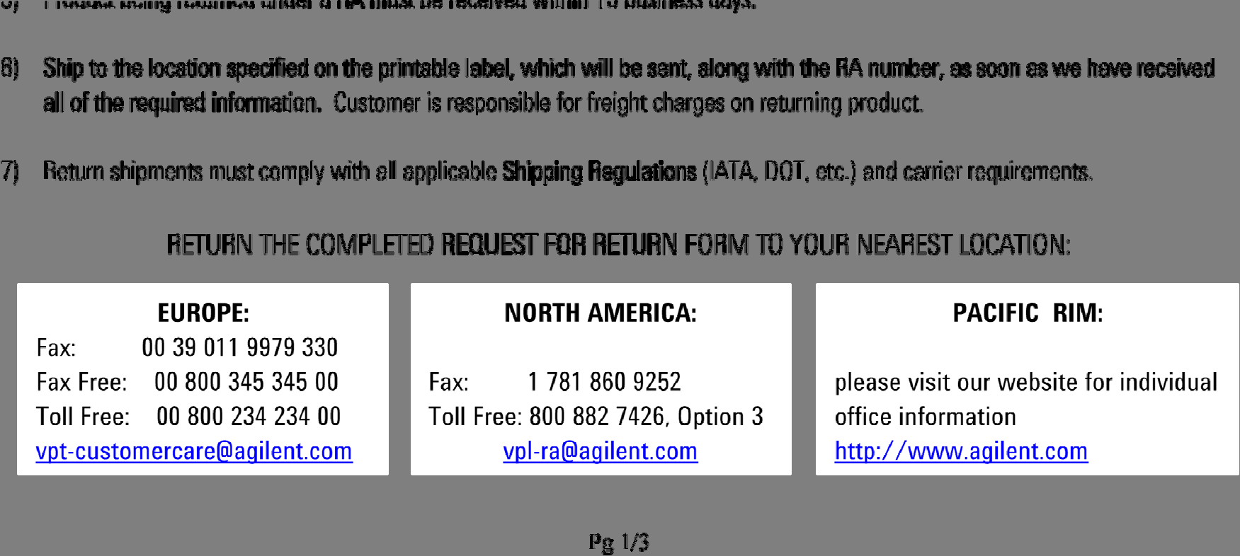
85
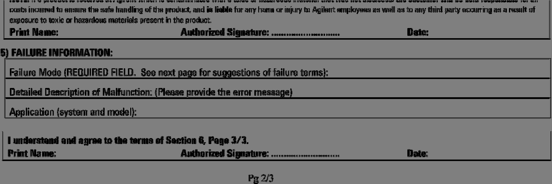
86

87
Ion Pumps Control Unit (Battery Backup)
") Ion Pumps Control Unit (Battery Backup) Model 829-5000R001 Manuale di Istruzioni Bedienungshandbuch Notice de Mode D Emploi User Manual 87-900-117-01 (D) 05/2011 Notices Agilent Technologies, Inc. 2011
Ion Pumps Control Unit (Battery Backup) Model 829-5000R001 Manuale di Istruzioni Bedienungshandbuch Notice de Mode D Emploi User Manual 87-900-117-01 (D) 05/2011 Notices Agilent Technologies, Inc. 2011
PRIMER WIRELESS STEREO HEADSET QUICK START GUIDE
 PRIMER WIRELESS STEREO HEADSET QUICK START GUIDE ! WARNING! BEFORE USING THIS PRODUCT, READ THE MANUALS FOR THIS ACCESSORY AND THE XBOX 360 CONSOLE (AND ANY OTHER APPLICABLE MANUALS) FOR IMPORTANT SAFETY
TECHNICAL MANUAL FT GEN 17
 IT MANUALE TECNICO EN TECHNICAL MANUAL FR MANUEL TECHNIQUE FT GEN 7 3 4 5 6 Schede opzionali Art. 5733 e Art. 5734 per Monitor serie Bravo Optional cards Art. 5733 and Art. 5734 for Bravo series Monitor
1. Raison de la modification
 T Service Documentation Technicocommerciale Information Technique Rubrique F Les régulations Nouvelle version de programme de la carte SU : F1.4 P5253 JS F 67580 Mertzwiller N ITOE0117 26/09/2011 FR 1.
SIMATIC. SIMATIC STEP 7 PID Professional V12. Welcome Tour. Totally Integrated Automation www.siemens.com/tia-portal-welcometour PORTAL
 SIMATIC STEP 7 PID Professional V12 Welcome Tour Totally Integrated Automation www.siemens.com/tia-portal-welcometour Totally Integrated Automation PORTAL www.siemens.com/tia-portal SIMATIC Siemens Aktiengesellschaft
Betriebsanleitung Programmierkabel PRKAB 560 Mode d emploi Câble de programmation PRKAB 560 Operating Instructions Programming cable PRKAB 560
 Betriebsanleitung Programmierkabel Câble de programmation Operating Instructions Programming cable B d-f-e 146 599-02 03.06 Camille Bauer AG Aargauerstrasse 7 CH-5610 Wohlen/Switzerland Telefon +41 56
Sun Type 7 Keyboard and Mouse Installation Guide
 Sun Type 7 Keyboard and Mouse Installation Guide Guide d installation du clavier et de la souris Sun Type 7 Sun Type 7-Tastatur Installationshandbuch Guida all installazione della tastiera e del mouse
185/55R15 1,4i 16V (74 kw) OE: Schrader 3007 21-5-21A/KE-17. Interio: ASC / ASS / CUS / Huf 2.4 / Huf 3.4 / SEC / SES / TTS / TTC
 OE: Schrader 3007 21-5-21A/KE-17. Interio: ASC / ASS / CUS / Huf 2.4 / Huf 3.4 / SEC / SES / TTS / TTC") 500 / 500C 09/07-312 FL 515009 500 / 500C CHF 104,00 ET 40 185/55R15 1,4i 16V (74 kw) 21-5-21A/KE-17 500 / 500C 312 Seismo SO 605 35 4 98 lichtsilber-lackiert Interio IN 605 35 4 98 lichtsilber-lackiert
500 / 500C 09/07-312 FL 515009 500 / 500C CHF 104,00 ET 40 185/55R15 1,4i 16V (74 kw) 21-5-21A/KE-17 500 / 500C 312 Seismo SO 605 35 4 98 lichtsilber-lackiert Interio IN 605 35 4 98 lichtsilber-lackiert
Manuel d installation et de maintenance (serrures LR128 E)
") Manuel d installation et de maintenance (serrures LR128 E) Manuel comprenant : Installation de la gâche GV et GVR :............................................ page 2 Position et réglage du shunt - Cales
Manuel d installation et de maintenance (serrures LR128 E) Manuel comprenant : Installation de la gâche GV et GVR :............................................ page 2 Position et réglage du shunt - Cales
Quick Start Guide This guide is intended to get you started with Rational ClearCase or Rational ClearCase MultiSite.
 Rational ClearCase or ClearCase MultiSite Version 7.0.1 Quick Start Guide This guide is intended to get you started with Rational ClearCase or Rational ClearCase MultiSite. Product Overview IBM Rational
Réserve Personnelle. Persönliche Reserve. Emprunter et épargner en fonction de vos besoins. Leihen und sparen je nach Bedarf
 crédit épargne Réserve Personnelle Emprunter et épargner en fonction de vos besoins Persönliche Reserve Leihen und sparen je nach Bedarf Réserve Personnelle Vous voulez disposer à tout moment des moyens
SunATM 4.0 Release Notes
 SunATM 4.0 Release Notes Sun Microsystems, Inc. 901 San Antonio Road Palo Alto, CA 94303-4900 USA 650 960-1300 Fax 650 969-9131 Part No.: 805-6553-10 March 1999, Revision A Copyright 1999 Sun Microsystems,
Your Pirelli VDSL router has been preconfigured with the following settings:
 Important Information & Installation Instructions VDSL (Analog) Dear Netstream customer Your Pirelli VDSL router has been preconfigured with the following settings: LAN IP Adress of the Pirelli router:
Important information. New SIMATIC HMI Panels. Migration made easy start now. SIMATIC HMI Panels. siemens.com/simatic-panels
 Important information New SIMATIC HMI Panels Migration made easy start now SIMATIC HMI Panels siemens.com/simatic-panels Totally Integrated Automation Portal (TIA Portal) est l environnement d ingénierie
P-W. 0,5 Nm. 2 Nm. Optional. fissare su piastra fix on the plate auf der Platte befestigen fixer sur plaque fijar en la placa
 7 P-W 8 5 Optional 4 nel caso P-W aggiungere il connettore optional e continuare con la sequenza della fig. 8 In case of P-W, the optional connector must be added and procedure as in picture 8 followed
Wie können meine Abschlüsse in Frankreich anerkannt werden?
 Wie können meine Abschlüsse in Frankreich anerkannt werden? Trotz der mittlerweile in Kraft getretenen europäischen Regelungen der beruflichen Anerkennung von Ausbildungen und Hochschuldiplomen, liegt
 3.2.6.1. Câblage type 3.2.6.2. Autres câblages RC1 : Sélection des courbes de charge SW1 : Sélection de la fonction BOOST RC1 SW1 Montage de 2 chargeurs en parallèle : NF EN 61000-6-1: Compatibilité
Oracle FS Data Protection Manager. Release Notes. Part Number E50336-01 Oracle FS Data Protection Manager release 3.5.
 Oracle FS Data Protection Manager Release Notes Part Number E50336-01 Oracle FS Data Protection Manager release 3.5.0 2014 December Copyright 2005, 2014, Oracle and/or its affiliates. All rights reserved.
WLAN Magic-Box einrichten S. 2 Installer WLAN Magic-Box p. 10 Installare WLAN Magic-Box p. 18 WLAN Magic-Box setup p. 26
 Swisscom (Schweiz) AG Contact Center CH-3050 Bern 07/2012 www.swisscom.ch WLAN einrichten S. 2 Installer WLAN p. 10 Installare WLAN p. 18 WLAN setup p. 26 YM.AP.4742.UM.SW.D00 WLAN On/Off WLAN On/Off Nous
J201. Übergänge Stahl / PE Pièces de transition Acier / PE Pezzo di transizione acciaio / PE
 J201 Übergänge Stahl / PE Pièces de transition Acier / PE Pezzo di transizione acciaio / PE 01.2012 J202 Übergangsstück Flansch / PE, PN5 Pièce de transition bride / PE, PN5 Raccordo di transizione flangia
Paxton. ins-20605. Net2 desktop reader USB
 Paxton ins-20605 Net2 desktop reader USB 1 3 2 4 1 2 Desktop Reader The desktop reader is designed to sit next to the PC. It is used for adding tokens to a Net2 system and also for identifying lost cards.
Router einrichten Installer le routeur Installare il router Router setup
 Swisscom (Schweiz) AG Contact Center CH-3050 Bern www.swisscom.ch 10010869 12/2014 IP Router einrichten Installer le routeur Installare il router Router setup Centro piccolo Wireless Ethernet 4 Internet
Grandes tendances et leurs impacts sur l acquisition de produits et services TI.
 Grandes tendances et leurs impacts sur l acquisition de produits et services TI. François Banville Partenaire exécutif chez Gartner Gartner is a registered trademark of Gartner, Inc. or its affiliates.
SERVEUR DÉDIÉ DOCUMENTATION
 SERVEUR DÉDIÉ DOCUMENTATION Release 5.0.6.0 19 Juillet 2013 Copyright 2013 GIANTS Software GmbH, All Rights Reserved. 1/9 CHANGE LOG Correction de bug divers (5.0.6.0) Ajout d une option de relance automatique
VERTIKA GENNIUS ACCESSORI. Passacavo - cable gland system - Motorkabelmontage - système passe câble - sistema de pasteca
 130 VERTIKA GENNIUS VERTIKA GENNIUS 131 Passacavo - cable gland system - Motorkabelmontage - système passe câble - sistema de pasteca Nuovo sistema passacavo motore per nascondere il cavo elettrico alla
AMARICAM JUNIOR 100M FRANCAIS ENGLISH DEUTSCH ITALIANO ESPANOL NEDERLANDS PORTUGUESES MANUEL UTILISATEUR USER S GUIDE BENUTZERHANDBUCH
 AMARICAM JUNIOR 100M MANUEL UTILISATEUR USER S GUIDE BENUTZERHANDBUCH GUIDA PER L UTENTE GUIA DEL USUARIO GEBRUIKERSGIDS MANUAL DO USUARIO FRANCAIS ENGLISH DEUTSCH ITALIANO ESPANOL NEDERLANDS PORTUGUESES
(51) Int Cl.: G06K 19/07 (2006.01) G06K 19/073 (2006.01)
 Int Cl.: G06K 19/07 (2006.01) G06K 19/073 (2006.01)") (19) TEPZZ 4Z_7Z6B_T (11) EP 2 401 706 B1 (12) FASCICULE DE BREVET EUROPEEN (4) Date de publication et mention de la délivrance du brevet: 22.04.201 Bulletin 201/17 (21) Numéro de dépôt: 711430.8 (22)
(19) TEPZZ 4Z_7Z6B_T (11) EP 2 401 706 B1 (12) FASCICULE DE BREVET EUROPEEN (4) Date de publication et mention de la délivrance du brevet: 22.04.201 Bulletin 201/17 (21) Numéro de dépôt: 711430.8 (22)
Notice Technique / Technical Manual
 Contrôle d accès Access control Encodeur USB Mifare ENCOD-USB-AI Notice Technique / Technical Manual SOMMAIRE p.2/10 Sommaire Remerciements... 3 Informations et recommandations... 4 Caractéristiques techniques...
Monitor LRD. Table des matières
 Folio :1/6 Table des matières 1.Installation du logiciel... 3 2.Utilisation du logiciel... 3 2.1.Description de la fenêtre de commande... 3 2.1.1.Réglage des paramètres de communication... 4 2.1.2.Boutons
INTRANET: outil de Knowledge management au sein de l entreprise
 ARIEL RICHARD-ARLAUD INTRANET: outil de Knowledge management au sein de l entreprise Ariel Richard-Arlaud I. Le Knowledge management L avènement de la technologie INTERNET bouleverse les habitudes et mentalités:
Informazioni su questo libro
 Informazioni su questo libro Si tratta della copia digitale di un libro che per generazioni è stato conservata negli scaffali di una biblioteca prima di essere digitalizzato da Google nell ambito del progetto
A propos de ce livre. Consignes d utilisation
 A propos de ce livre Ceci est une copie numérique d un ouvrage conservé depuis des générations dans les rayonnages d une bibliothèque avant d être numérisé avec précaution par Google dans le cadre d un
Quick-Manual. Comfort VS1
 Quick-Manual Comfort VS1 Inhalt Contenu Contenuto 1. So legen Sie die SIM-Karte ein 3 2. So laden Sie den Akku auf 4 3. Und wozu sind all die Tasten da? 5 4. Wie speichern Sie neue Kontakte in Ihrem Telefonbuch?
en SCÈNE RATIONAL Rational Démonstration SDP : automatisation de la chaîne de développement Samira BATAOUCHE sbataouche@fr.ibm.com
 Rational Démonstration SDP : automatisation de la chaîne de développement Samira BATAOUCHE sbataouche@fr.ibm.com Fabrice GRELIER fabrice.grelier@fr.ibm.com RATIONAL en SCÈNE 2007 IBM Corporation Objectif
Swap: Utilisation et risques Approche de gestion pour les consommateurs
 Paris 5 avril 2013 Swap: Utilisation et risques Approche de gestion pour les consommateurs Serge LESCOAT Associé INDAR ENERGY Conseiller en Investissements Financiers Membre du CNCIF Association agréé
Quick Installation Guide. SwitchView IP. Attaching the host computer to the SwitchView IP device
 Quick Installation Guide The following instructions will help you connect your device. Should you require further assistance, please To connect a remote access device to a computer consult your installer/user
Wobe. www.lea-networks.com
 Wobe www.lea-networks.com Wobe Le Hotspot 3G/WiFi de poche Wobe est le premier routeur mobile 3G/WiFi autonome permettant de connecter à internet ses terminaux WiFi (PC, tablette tactile, console de jeux
Package Contents. System Requirements. Before You Begin
 Package Contents DWA-125 Wireless 150 USB Adapter CD-ROM (contains software, drivers, and manual) Cradle If any of the above items are missing, please contact your reseller. System Requirements A computer
Cheque Holding Policy Disclosure (Banks) Regulations. Règlement sur la communication de la politique de retenue de chèques (banques) CONSOLIDATION
 Regulations. Règlement sur la communication de la politique de retenue de chèques (banques) CONSOLIDATION") CANADA CONSOLIDATION CODIFICATION Cheque Holding Policy Disclosure (Banks) Regulations Règlement sur la communication de la politique de retenue de chèques (banques) SOR/2002-39 DORS/2002-39 Current to
CANADA CONSOLIDATION CODIFICATION Cheque Holding Policy Disclosure (Banks) Regulations Règlement sur la communication de la politique de retenue de chèques (banques) SOR/2002-39 DORS/2002-39 Current to
Remote control with HI-PULL lock Controllo a distanza maniglia HI-PULL Fermeture à télécommande pour poignée HI-PULL Fernsteuerung für HI-PULL
 Remote control with HI-PULL lock Controllo a distanza maniglia HI-PULL Fermeture à télécommande pour poignée HI-PULL Fernsteuerung für HI-PULL Verschluss Mando a distancia del cierre falleba HI-PULL Informazioni
GIGABIT PCI DESKTOP ADAPTER DGE-530T. Quick Installation Guide+ Guide d installation+
 GIGABIT PCI DESKTOP ADAPTER Quick Installation Guide+ Guide d installation+ Check Your Package Contents Quick Installation Guide Gigabit Ethernet PCI Adapter CD with Manual and Drivers DO NOT insert the
Commutateur clavier-écran-souris 2/4 ports DKVM-2/4. Guide d utilisation. Rév. 1.3
 Commutateur clavier-écran-souris 2/4 ports DKVM-2/4 Guide d utilisation Rév. 1.3 Table des matières Introduction...1 Fonctionnalités...2 Contenu de l emballage...2 Installation du matériel...3 Face avant...
Parcage. Bases légales. Office des ponts et chaussées du canton de Berne. Tiefbauamt des Kantons Bern. Bau-, Verkehrsund Energiedirektion
 Tiefbauamt des Kantons Bern Bau-, Verkehrsund Energiedirektion Office des ponts et chaussées du canton de Berne Direction des travaux publics, des transports et de l'énergie Tâches spéciales Technique
Guide de récupération de Windows Server 2003 R2 pour serveurs Sun x64
 Guide de récupération de Windows Server 2003 R2 pour serveurs Sun x64 Sommaire Introduction 1 Procédure de réinstallation 1 Documentation associée 5 Vos commentaires nous sont utiles 5 Introduction Ce
ASSEMBLYcomponents H 10. Grundplatte. Base plate. Plaque de base BEM 3 BEW 3. FP 3 Base plate 30001121 1,1kg BEM 6 BEM 6D BEW 6
 S ASSEMBLYcomponents Base plate FP H 10 Die Grundplatten sind aus Stahl 700 N/mm 2 hergestellt. Sie sind brüniert und beidseitig geschliffen. Die Passfedern werden mitgeliefert. Die SUHNER-Bearbeitungseinheiten
First Nations Assessment Inspection Regulations. Règlement sur l inspection aux fins d évaluation foncière des premières nations CONSOLIDATION
 CANADA CONSOLIDATION CODIFICATION First Nations Assessment Inspection Regulations Règlement sur l inspection aux fins d évaluation foncière des premières nations SOR/2007-242 DORS/2007-242 Current to September
Die Fotografie als Lebensgefühl, mit all ihren Facetten und Ausdrucksmöglichkeiten,
 PORTFOLIO Claus Rose Photography as a way of living, with all its aspects and opportunities for expression, became my passion at an early stage. In particular the magic of nude photography, which lends
Contrôle d'accès Access control. Notice technique / Technical Manual
 p.1/18 Contrôle d'accès Access control INFX V2-AI Notice technique / Technical Manual p.2/18 Sommaire / Contents Remerciements... 3 Informations et recommandations... 4 Caractéristiques techniques... 5
Subject to the terms of this Agreement, Adobe hereby grants you a nonexclusive,
 ADOBE SYSTEMS INCORPORATED OPEN SOURCE LICENSE NOTICE TO USER: Adobe Systems Incorporated is providing the Software Documentation for use under the terms of this Agreement. Any use, reproduction, modification
Règlement sur le télémarketing et les centres d'appel. Call Centres Telemarketing Sales Regulation
 THE CONSUMER PROTECTION ACT (C.C.S.M. c. C200) Call Centres Telemarketing Sales Regulation LOI SUR LA PROTECTION DU CONSOMMATEUR (c. C200 de la C.P.L.M.) Règlement sur le télémarketing et les centres d'appel
SAP Best Practices. Commande en ligne pour les clients et les partenaires SAP
 SAP Best Practices Commande en ligne pour les clients et les partenaires SAP 1. Disponibilité de SAP Best Practices 2. Télédéchargement de SAP Best Practices Disponibilité de SAP Best Practices Qui peut
Guide de démarrage du système modulaire Sun Blade 6000
 Guide de démarrage du système modulaire Sun Blade 6000 Ce document contient des informations de base sur la configuration du système modulaire Sun Blade 6000. Vous trouverez des informations détaillées
Activity Space: acrobatica a squadre
 Activity Space: acrobatica a squadre Nell activity show dell acrobatica a squadre potete costruire diverse forme. Provate a formare diverse figure. Potete anche creare delle nuove forme voi stessi. È importante
Logitech Tablet Keyboard for Windows 8, Windows RT and Android 3.0+ Setup Guide Guide d installation
 Logitech Tablet Keyboard for Windows 8, Windows RT and Android 3.0+ Setup Guide Guide d installation English.......................................... 3 Français.........................................
Portrait Société. Relations. Données éconographiques locales. Contacts
 Industrie AG Adresse : Zürcherstrasse 5 8952 Schlieren Case postale : Postfach 150 8952 Schlieren Pays : Schweiz Canton : ZH Langage : D Web : SicCode : Branche : www.industrie.ch MEC Fabric. de biens
Téléphone Voix sur IP Telefono Voice over IP. Mode d emploi Istruzioni per l uso IP-6
 Téléphone Voix sur IP Telefono Voice over IP Mode d emploi Istruzioni per l uso IP-6 2 IP-6 Version 1.0-03.03.2005 Mode d emploi 3 Istruzioni per l uso_33 2 - Table des matières- 1 Généralités... 5 1.1
Optimisez la gestion de vos projets IT avec PPM dans le cadre d une réorganisation. SAP Forum, May 29, 2013
 Optimisez la gestion de vos projets IT avec PPM dans le cadre d une réorganisation SAP Forum, May 29, 2013 Optimisez la gestion de vos projets IT avec PPM dans le cadre d une réorganisation Frédérique
Phone Manager Soutien de l'application OCTOBER 2014 DOCUMENT RELEASE 4.1 SOUTIEN DE L'APPLICATION
 Phone Manager Soutien de l'application OCTOBER 2014 DOCUMENT RELEASE 4.1 SOUTIEN DE L'APPLICATION Sage CRM NOTICE The information contained in this document is believed to be accurate in all respects but
Quick start guide. www.philips.com/support HTL1170B
 For product support, visit Para obtener asistencia técnica, visite Pour en savoir plus sur l assistance sur les produits, visitez le site www.philips.com/support HTL1170B Quick start guide P&F USA, Inc.
CR3103 CAN. GSM Triband-Modem zur Übertragung von SMS-Meldungen und Datenpaketen. CAN-Gateway mit CANopen-Schnittstelle. Betriebsspannung 10...
 Steuerungssysteme CR0,6 8, GSM Triband-Modem zur Übertragung von SMS-Meldungen und Datenpaketen -Gateway mit open-schnittstelle Betriebsspannung 0...0 V DC 8,6 ) FME-Antennenstecker ) open Schnittstelle
ASSEMBLY INSTRUCTIONS DIRECTIVES POUR L'ASSEMBLAGE ombre pendant lamp lampe suspendue à tons dégradés, chocolat
 ASSEMBLY INSTRUCTIONS DIRECTIVES POUR L'ASSEMBLAGE ombre pendant lamp lampe suspendue à tons dégradés, chocolat SKU 2728089 INSTRUCTIONAL MANUAL MANUEL D'INSTRUCTIONS 270/2707 COMPONENT LIST LISTE DES
ASSEMBLY INSTRUCTIONS DIRECTIVES POUR L'ASSEMBLAGE luster chandelier lamp chandelier à trois branches en verre lustré
 ASSEMBLY INSTRUCTIONS DIRECTIVES POUR L'ASSEMBLAGE luster chandelier lamp chandelier à trois branches en verre lustré SKU 2711592 INSTRUCTIONAL MANUAL MANUEL D'INSTRUCTIONS 270/2707 COMPONENT LIST LISTE
Medienmitteilung zur Konferenz Opendata.ch 2015 am 1. Juli an der Universität Bern
 Opendata.ch info@opendata.ch 8000 Zürich 7. Juni 2015 Medienmitteilung zur Konferenz Opendata.ch 2015 am 1. Juli an der Universität Bern Communiqué de presse à propos de la conférence Opendata.ch/2015
12 mm Bodenstärke Piso em resina Slim espessura 12 mm Sol en résine «slim» épaisseur 12 mm
 Te c h n i s c h e i n f o r m a t i o n e n I n f o r m a ç a o I n f o r m a t i o n T é c n i c a t é c h n i q u e Fertigbad in Superleichtbauweise in verzinkter Stahlkonstruktion Banheiro pré-fabricado
Wandluftdurchlass WAVE-ARC Typ WA Diffuseur mural WAVE-ARC type WA
 Int. Modellschutz angem. / Prot. int. des mod. dép. Trox Hesco (Schweiz) AG Anwendung Der rechteckige Wandluftdurchlass WAVE-ARC, der mit dem Anschlusskasten eine Einheit bildet, kommt vorwiegend über
CP, 11, 6, 7, 9 1, 10 1 LBA
 1. Extrait de l arrêt de la Cour des affaires pénales dans la cause Ministère public de la Confédération contre A. et consorts du 18 septembre 2008 et complément du 18 mai 2009 (SK.2007.28) Blanchiment
Schnellverschlusskupplungen in Messing Accouplements rapides en laiton
 Schnellverschlusskupplungen in Messing Accouplements rapides en laiton Typ 02 M3, Schlauch 2-3 mm NW 1,5 Kv 0,053 181 Type 02 M3, tuyaux 2-3 mm DN 1,5 Kv 0.053 Typ 20 M5 1 /8, Schlauch 3 6 mm NW 2,7 Kv
VKF Brandschutzanwendung Nr. 11109
 Vereinigung Kantonaler Feuerversicherungen Auskunft über die Anwendbarkeit gemäss den erischen Brandschutzvorschriften VKF Brandschutzanwendung Nr. 11109 Gruppe 302 Gesuchsteller Raumheizer für feste Brennstoffe
Nice HSRE12. Home security radio receiver. EN - Installation instructions. IT - Istruzioni per l installazione. FR - Instructions pour l installation
 EN - Installation instructions IT - Istruzioni per l installazione FR - Instructions pour l installation ES - Instrucciones para la instalación DE - Anleitungen für die Installation Nice HSRE12 Home security
03/2013. Mod: WOKI-60IP/TR. Production code: DTWIC 6000
 03/2013 Mod: WOKI-60IP/TR Production code: DTWIC 6000 ENCASTRABLE INDUCTION DROP IN INDUCTION 11/2011 TECHNICAL FEATURES DOCUMENTATION S.A.V. Notice d utilisation : FX00326-A Guide d intervention : ---
Guide D installation de l adaptateur téléphonique analogique HandyTone
 Guide D installation de l adaptateur téléphonique analogique HandyTone Numéro de pièce: 418-02010-10 Version du document: 1.0 Handytone 502 & HandyTone 503 HandyTone 286 & HandyTone 486 Dernière mise à
Information Equipment
 PLM Information Equipment SOMMAIRE: DESCRIPTION ET CARACTERISTIQUES PRINCIPALES PLAN D INSTALLATION INFORMATIONS TECHNIQUES CONFIGURATION Sealed Air S.A.S. 53 rue St Denis Boîte Postale 9 F-28234 EPERNON
Guide d'installation rapide TFM-560X YO.13
 Guide d'installation rapide TFM-560X YO.13 Table of Contents Français 1 1. Avant de commencer 1 2. Procéder à l'installation 2 Troubleshooting 6 Version 06.08.2011 16. Select Install the software automatically
86 rue Julie, Ormstown, Quebec J0S 1K0
 Tel : (450) 829-4200 Fax : (450) 829-4204 Email : info@rout-am.com Contacts: Jean Côté jean@rout-am.com Jocelyn Côté jocelyn@rout-am.com Dispatch info@rout-am.com Phone: (450) 829-4200 Fax: (450) 829-4204
This is a preview - click here to buy the full publication NORME INTERNATIONALE INTERNATIONAL STAN DARD. Telecontrol equipment and systems
 NORME INTERNATIONALE INTERNATIONAL STAN DARD CEI IEC 870-3 Première édition First edition 1989-03 Matériels et systèmes de téléconduite Troisième partie: Interfaces (caractéristiques électriques) Telecontrol
Solaris Server Intranet Extension 1.0 Licensing Guide
 Solaris Server Intranet Extension 1.0 Licensing Guide SunSoft, Inc. A Sun Microsystems, Inc. Business 2550 Garcia Avenue Mountain View, CA 94043 USA 415 960-1300 fax 415 969-9131 Part No.:805-1623-10 Revision
Dichiarazione di Conformità CE ( Dichiarazione del costruttore )
") CODICE MODELLO DATA 230 / 024 27.03.2009 Dichiarazione di Conformità CE ( Dichiarazione del costruttore ) Il costruttore: DICHIARA CHE IL SEGUENTE APPARATO: Nome dell' apparato Tipo di apparato Rilevatore
CODICE MODELLO DATA 230 / 024 27.03.2009 Dichiarazione di Conformità CE ( Dichiarazione del costruttore ) Il costruttore: DICHIARA CHE IL SEGUENTE APPARATO: Nome dell' apparato Tipo di apparato Rilevatore
BGSM-120/100. I F n. Comunicatori di Allarme GSM/GPRS Transmetteurs d'alarme GSM/GPRS GSM/GPRS Alarmcommunicators ISO 14001 9191.
 ISO 14001 9191.BNT2 BGSM-120/100 ISO 14001 IT-52588 Comunicatori di Allarme GSM/GPRS Transmetteurs d'alarme GSM/GPRS GSM/GPRS Alarmcommunicators I F n 0470 No. I Parti F Composants n Onderdelen 1 Antenna
Tom Pertsekos. Sécurité applicative Web : gare aux fraudes et aux pirates!
 Tom Pertsekos Sécurité applicative Web : gare aux fraudes et aux pirates! Sécurité Le mythe : «Notre site est sûr» Nous avons des Nous auditons nos Firewalls en place applications périodiquement par des
Nice HSRE12. Home security radio receiver. EN - Installation instructions. IT - Istruzioni per l installazione. FR - Instructions pour l installation
 EN - Installation instructions IT - Istruzioni per l installazione FR - Instructions pour l installation ES - Instrucciones para la instalación DE - Anleitungen für die Installation Nice HSRE12 Home security
RAMOS. Etude d Application. www.conteg.com. All rights reserved, CONTEG 2013
 RAMOS Etude d Application 2012 CONTEG, spol. s r.o. All rights reserved. No part of this publication may be used, reproduced, photocopied, transmitted or stored in any retrieval system of any nature, without
Mediacast Setup. Mediacasting from UPnP compatible devices
 Models: dgimd13 Mediacast Setup Mediacasting from UPnP compatible devices Please read these instructions carefully prior to installation Important Note: This procedure was written in conjunction with an
F1 Security Requirement Check List (SRCL)
") F1 Security Requirement Check List (SRCL) Liste de vérification des exigences relatives à la sécurité (LVERS) Cyber Protection Supply Arrangement (CPSA) Arrangement en matière d approvisionnement en cyberprotection
F1 Security Requirement Check List (SRCL) Liste de vérification des exigences relatives à la sécurité (LVERS) Cyber Protection Supply Arrangement (CPSA) Arrangement en matière d approvisionnement en cyberprotection
SAP Runs SAP Reporting Opérationnel & BI avec HANA et SAP Analytics. Pierre Combe, Enterprise Analytics Juin, 2015
 SAP Runs SAP Reporting Opérationnel & BI avec HANA et SAP Analytics Pierre Combe, Enterprise Analytics Juin, 2015 Agenda SAP Enterprise Analytics qui sommes-nous? Acteur clé de l innovation à SAP Présentation
HUAWEI TECHNOLOGIES CO., LTD. channelroad. A better way. Together.
 HUAWEI TECHNOLOGIES CO., LTD. channelroad A better way. Together. Partenaires sur la nouvelle Route de la soie Progresser le long d une nouvelle Route de la soie et être partenaire de Huawei présentent
Folio Case User s Guide
 Fujitsu America, Inc. Folio Case User s Guide I N S T R U C T I O N S This Folio Case is a stylish, lightweight case for protecting your Tablet PC. Elastic Strap Pen Holder Card Holders/ Easel Stops Figure
Elektrisk kontakt System P8 supportsystem Electrical connection System P8 Support system Système de connexion électrique Système de support P8
 Elektrisk kontakt System P8 supportsystem Electrical connection System P8 Support system Système de connexion électrique Système de support P8 Elektrischer Anschluss-System P8 Support System SE Elektrisk
22/09/2014 sur la base de 55,03 euros par action
 CORPORATE EVENT NOTICE: Amortissement d'orane Reprise de cotation PUBLICIS GROUPE S.A. PLACE: Paris AVIS N : PAR_20140902_06559_EUR DATE: 02/09/2014 MARCHE: EURONEXT PARIS Amortissement en titres et en
Registre cantonal tessinois des volontaires sains. Médecins et pharmaciens cantonaux Martigny, 25 mai 2000 G. M. Zanini
 Registre cantonal tessinois des volontaires sains Médecins et pharmaciens cantonaux Martigny, 25 mai 2000 G. M. Zanini 1.Pourquoi un registre au Tessin? 2.Quels sont les objectifs? 3.Sur quelle base le
VDE Prüf- und Zertifizierungsinstitut Zeichengenehmigung
 VDE Prüf- und Zertifizierungsinstitut Ausweis-Nr. / Certificate No. 40033326 Blatt / page 2 Name und Sitz des Genehmigungs-Inhabers / Name and registered seat of the Certificate holder Enphase Energy,
Ä.?0ùä EPZ. Montageanleitung Mounting Instructions Instructions de montage EPZ 10202
 EDK10202EZ3.?0ù Ä.?0ùä EPZ Montageanleitung Mounting Instructions Instructions de montage EPZ 10202 Extension Board II für Drive PLC Extension Board II for Drive PLC Carte d extension II pour Drive PLC
INVESTMENT REGULATIONS R-090-2001 In force October 1, 2001. RÈGLEMENT SUR LES INVESTISSEMENTS R-090-2001 En vigueur le 1 er octobre 2001
 FINANCIAL ADMINISTRATION ACT INVESTMENT REGULATIONS R-090-2001 In force October 1, 2001 LOI SUR LA GESTION DES FINANCES PUBLIQUES RÈGLEMENT SUR LES INVESTISSEMENTS R-090-2001 En vigueur le 1 er octobre
SUGARCRM Sugar Open Source Guide d Installation de French SugarCRM Open Source Version 4.2
 SUGARCRM Sugar Open Source Guide d Installation de French SugarCRM Open Source Version 4.2 Version 1.0.5 Mentions légales Mentions légales Ce document est susceptible de modification à tout moment sans
AUFZIEHSERVICE SERVICE DE LAMINAGE
 SEVICE DE LAMINAGE Gratis-Fax 0800 300 444 Telefon 071 913 94 94 Online bestellen www.wilerrahmen.ch 2015 359 SEVICE DE LAMINAGE 360 2015 Fax gratuit 0800 300 444 Téléphone 071 913 94 94 Commande en ligne
SERIE TS-770 SYSTEME CONFERENCE
 SERIE TS-770 SYSTEME CONFERENCE Le système de conférence à fils de TOA installation, utilisation et extension faciles, Avec la participation à distance via IP ou téléphone. Système de conférence compact,
SWISS MASTER SERIES D YVERDON-LES BAINS les 30 avril, 1er et 2 mai 2010. Exclusivement par Internet sur le site de Swiss Badminton
 -2- SWISS MASTER SERIES D YVERDON-LES BAINS les 30 avril, 1er et 2 mai 2010 Organisateur Directeur du tournoi Badminton Club Yverdon-les-Bains, www.badmintonyverdon.ch Rosalba Dumartheray, 078 711 66 92,
uno CoLLECTIon UNO Collection PARTICOLARI FINITURA - DÉTAILS FINITION - SPEZIELLE VEREDELUNGEN DÉTAILS FInITIon
 UNO COLLECTION CARATTERISTICHE TECNICHE DEL PRODOTTO CARACTÉRISTIQUES TECHNIQUES DU PRODUIT TECHNISCHE EIGENSCHAFTEN uno CoLLECTIon STRUTTURA - STRUCTURE - STRUKTUR Pannello in nobilitato melaminico idro.
Règlement sur les baux visés à la Loi no 1 de 1977 portant affectation de crédits. Appropriation Act No. 1, 1977, Leasing Regulations CODIFICATION
 CANADA CONSOLIDATION CODIFICATION Appropriation Act No. 1, 1977, Leasing Regulations Règlement sur les baux visés à la Loi no 1 de 1977 portant affectation de crédits C.R.C., c. 320 C.R.C., ch. 320 Current
NORME INTERNATIONALE INTERNATIONAL STANDARD. Dispositifs à semiconducteurs Dispositifs discrets. Semiconductor devices Discrete devices
 NORME INTERNATIONALE INTERNATIONAL STANDARD CEI IEC 747-6-3 QC 750113 Première édition First edition 1993-11 Dispositifs à semiconducteurs Dispositifs discrets Partie 6: Thyristors Section trois Spécification